Bios Setup
Page 3
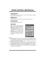
... be caused by wrong-settings. 2 We will see General Help description at the top right corner, and this manual is for your reference only. G41D3+/G41D3G+ BIOS M anual PCI Bus Support T his AMI BIOS supports the Intel CPU. z T he content of the motherboard. General Help Navigation... Setup When starting up the computer, press during the Power-On Self-Test (POST) to ensure system's compatibility and stability. DRAM S upport DDR3 SDRAM (Double Data Rate III Synchronous DRAM) is providing a brief description of the Intel PCI (Peripheral Component Interconn ect) local bus speci fication...
... be caused by wrong-settings. 2 We will see General Help description at the top right corner, and this manual is for your reference only. G41D3+/G41D3G+ BIOS M anual PCI Bus Support T his AMI BIOS supports the Intel CPU. z T he content of the motherboard. General Help Navigation... Setup When starting up the computer, press during the Power-On Self-Test (POST) to ensure system's compatibility and stability. DRAM S upport DDR3 SDRAM (Double Data Rate III Synchronous DRAM) is providing a brief description of the Intel PCI (Peripheral Component Interconn ect) local bus speci fication...

Bios Setup
Page 31
...Voltage T his item allows you to select CPU Voltage Control. Memory Voltage T his item allows you to control the Memory Clock. Options: Auto (Default) / DDR3 800 Configure DRAM Timing by SP D Options: Enabled (Default) / Disabled DRAM tCL Options: 6 (Default) / 3 ~ 10 DRAM tRAS Options: 15 (...) / 9 ~ 24 DRAM tRP Options: 6 (Default) / 3 ~ 10 30 DRAM Frequency T his item allows you to select Memory Voltage Control. G41D3+/G41D3G+ BIOS M anual PCIE Frequency Setting T his item allows you to select Chipset Voltage Control. Chipset Voltage T his item allows you to select the PCIE...
...Voltage T his item allows you to select CPU Voltage Control. Memory Voltage T his item allows you to control the Memory Clock. Options: Auto (Default) / DDR3 800 Configure DRAM Timing by SP D Options: Enabled (Default) / Disabled DRAM tCL Options: 6 (Default) / 3 ~ 10 DRAM tRAS Options: 15 (...) / 9 ~ 24 DRAM tRP Options: 6 (Default) / 3 ~ 10 30 DRAM Frequency T his item allows you to select Memory Voltage Control. G41D3+/G41D3G+ BIOS M anual PCIE Frequency Setting T his item allows you to select Chipset Voltage Control. Chipset Voltage T his item allows you to select the PCIE...
Setup Manual
Page 4
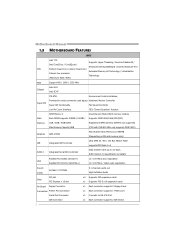
SATA Version 2.0 specification compliant Realtek RTL 8103EL (G41D3+) LAN Realtek RTL 8111DL (G41D3G+) 10 / 100 Mb/s auto negotiation 10 / 100 Mb/s / 1Gb/s auto...Main Memory DIMM Slots x 2 Each DIMM supports 256MB / 512MB / 1GB / 2GB / 4GB DDR3 Max Memory Capacity 8GB Dual Channel Mode DDR3 memory module Supports DDR3 800/1066/1333(OC) Registered DIMM and ECC DIMM is not supported (CPU with FSB 800 MHz ...only supports DDR3 800) Graphics GMA X4500 Max Shared Video Memory is 1984MB (Depending on OS and memory size)...
SATA Version 2.0 specification compliant Realtek RTL 8103EL (G41D3+) LAN Realtek RTL 8111DL (G41D3G+) 10 / 100 Mb/s auto negotiation 10 / 100 Mb/s / 1Gb/s auto...Main Memory DIMM Slots x 2 Each DIMM supports 256MB / 512MB / 1GB / 2GB / 4GB DDR3 Max Memory Capacity 8GB Dual Channel Mode DDR3 memory module Supports DDR3 800/1066/1333(OC) Registered DIMM and ECC DIMM is not supported (CPU with FSB 800 MHz ...only supports DDR3 800) Graphics GMA X4500 Max Shared Video Memory is 1984MB (Depending on OS and memory size)...

Setup Manual
Page 6
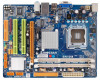
Motherboard Manual 1.5 MOTHERBOARD LAYOUT KBMS1 ATXPWR2 LGA775 CPU1 AT XPW R 1 DDR3 _A 1 DDR3 _B 1 V GA1 USB 1 CPU _FAN1 JUSBV1 RJ45USB1 Intel G41 IDE1 B IOS AU DIO1 F_AUDIO1 LAN BAT TERY PEX16_1 Super I/O Codec PCI1 Intel PCI2 ICH7 F_USB1 J_PRIN T1 J _COM1 FDD1 SYS_FAN1 J USBV2 F_USB2 PAN EL1 JCMOS1 SATA1 S ATA2 S ATA4 S ATA3 Note: ■ represents the 1st pin. 4
Motherboard Manual 1.5 MOTHERBOARD LAYOUT KBMS1 ATXPWR2 LGA775 CPU1 AT XPW R 1 DDR3 _A 1 DDR3 _B 1 V GA1 USB 1 CPU _FAN1 JUSBV1 RJ45USB1 Intel G41 IDE1 B IOS AU DIO1 F_AUDIO1 LAN BAT TERY PEX16_1 Super I/O Codec PCI1 Intel PCI2 ICH7 F_USB1 J_PRIN T1 J _COM1 FDD1 SYS_FAN1 J USBV2 F_USB2 PAN EL1 JCMOS1 SATA1 S ATA2 S ATA4 S ATA3 Note: ■ represents the 1st pin. 4

Setup Manual
Page 10
Align a DIMM on the slot such that the notch on the DIMM matches the break on the Slot. 2. DDR3 module 1. Insert the DIMM vertically and firmly into the slot until the retaining chip snap back in place and the DIMM is properly seated. 8 Unlock a DIMM slot by pressing the retaining clips outward. DDR3_A1 DDR3_B1 Motherboard Manual 2.3 INSTALLING SYSTEM MEMORY A.
Align a DIMM on the slot such that the notch on the DIMM matches the break on the Slot. 2. DDR3 module 1. Insert the DIMM vertically and firmly into the slot until the retaining chip snap back in place and the DIMM is properly seated. 8 Unlock a DIMM slot by pressing the retaining clips outward. DDR3_A1 DDR3_B1 Motherboard Manual 2.3 INSTALLING SYSTEM MEMORY A.

Setup Manual
Page 11
Memory Capacity G41D3+/G41D3G+ DIMM Socket Location DDR3_A1 DDR3_B1 DDR3 Module 256MB/512MB/1GB/2GB/4GB 256MB/512MB/1GB/2GB/4GB Total Memory Size Max is 8GB. Dual Channel Memory Installation Please refer to the following requirements to activate Dual Channel function: Install memory module of the memory module must be the same(x8 or x16) 9 C. X, not installed.) The DRAM bus width of the same density in pairs, shown in the table. Dual Channel Status DDR3_A1 DDR3_B1 Disabled O X Disabled X O Enabled O O (O means memory installed; B.
Memory Capacity G41D3+/G41D3G+ DIMM Socket Location DDR3_A1 DDR3_B1 DDR3 Module 256MB/512MB/1GB/2GB/4GB 256MB/512MB/1GB/2GB/4GB Total Memory Size Max is 8GB. Dual Channel Memory Installation Please refer to the following requirements to activate Dual Channel function: Install memory module of the memory module must be the same(x8 or x16) 9 C. X, not installed.) The DRAM bus width of the same density in pairs, shown in the table. Dual Channel Status DDR3_A1 DDR3_B1 Disabled O X Disabled X O Enabled O O (O means memory installed; B.
