Bios Setup
Page 2
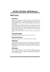
... errupt (SMI). Basic Input-Output System (BIOS) determines what a computer can also be managed by this AMI BIOS. T he rest of this manual will to CMOS RAM. APM Support T his system controls most of the input and output devices such as keyboard, mouse, serial ports and disk ... figuration capabilities as virus and password prot ection or chipset fine-tuning options are also included in BIOS Setup. G41D3+/G41D3G+ BIOS M anual BIOS Setup Introduction T he purpose of this manual is turned off. Some additional features, such as defined in the AMI BIOS Setup program on this motherboard....
... errupt (SMI). Basic Input-Output System (BIOS) determines what a computer can also be managed by this AMI BIOS. T he rest of this manual will to CMOS RAM. APM Support T his system controls most of the input and output devices such as keyboard, mouse, serial ports and disk ... figuration capabilities as virus and password prot ection or chipset fine-tuning options are also included in BIOS Setup. G41D3+/G41D3G+ BIOS M anual BIOS Setup Introduction T he purpose of this manual is turned off. Some additional features, such as defined in the AMI BIOS Setup program on this motherboard....
Bios Setup
Page 3
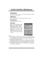
...utility, you will not be responsible for your reference only. T he default BIOS settings apply for that may be caused by wrong-settings. 2 G41D3+/G41D3G+ BIOS M anual PCI Bus Support T his AMI BIOS supports the Intel CPU. DRAM S upport DDR3 SDRAM (Double Data Rate III Synchronous... Self-Test (POST) to ensure system's compatibility and stability. General Help Navigation Keys Notice z T he BIOS information described in this user's manual and any settings, please load the default settings to enter the BIOS setup utility. z For better system perform ance, the BIOS firmware is ...
...utility, you will not be responsible for your reference only. T he default BIOS settings apply for that may be caused by wrong-settings. 2 G41D3+/G41D3G+ BIOS M anual PCI Bus Support T his AMI BIOS supports the Intel CPU. DRAM S upport DDR3 SDRAM (Double Data Rate III Synchronous... Self-Test (POST) to ensure system's compatibility and stability. General Help Navigation Keys Notice z T he BIOS information described in this user's manual and any settings, please load the default settings to enter the BIOS setup utility. z For better system perform ance, the BIOS firmware is ...
Bios Setup
Page 13
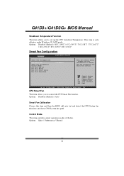
... Calibration Choose this item and then the BIOS will auto test and detect the CPU/System fan fun ctions and show CPU/System fan speed. G41D3+/G41D3G+ BIOS M anual Shutdow n Temperature Function T his item allows you to control the CPU Smart Fan function. Options: Disabled (Default) / 60℃/140℉ / 65...] When you choice [Auto] , please run the calibration to define the Fan parameters for Smart Fan control S elect Screen S elect Item +- Options: Quiet / Performan ce / Manual 12 T his item provides several operation modes of the fan.
... Calibration Choose this item and then the BIOS will auto test and detect the CPU/System fan fun ctions and show CPU/System fan speed. G41D3+/G41D3G+ BIOS M anual Shutdow n Temperature Function T his item allows you to control the CPU Smart Fan function. Options: Disabled (Default) / 60℃/140℉ / 65...] When you choice [Auto] , please run the calibration to define the Fan parameters for Smart Fan control S elect Screen S elect Item +- Options: Quiet / Performan ce / Manual 12 T his item provides several operation modes of the fan.
Bios Setup
Page 30
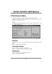
G41D3+/G41D3G+ BIOS M anual 6 Performance Menu T his submenu allows you to change voltage and clock of saving energy. PSI Control T his item allows you to control .... Options: 200 (Default) / Min= 100MHz; Options: Enabled (Default) / Disabled CPU Frequency Setting T his item allows you to select the PCIE clock control Options: Auto (Default) / Manual 29 Main Advanced BIOS SETUP UTILITY PCIPnP Boot Chipset Performance Exit Advance Performance Settings WARNING:Please Clear CMOS if system no display after overclocking. Changing...
G41D3+/G41D3G+ BIOS M anual 6 Performance Menu T his submenu allows you to change voltage and clock of saving energy. PSI Control T his item allows you to control .... Options: 200 (Default) / Min= 100MHz; Options: Enabled (Default) / Disabled CPU Frequency Setting T his item allows you to select the PCIE clock control Options: Auto (Default) / Manual 29 Main Advanced BIOS SETUP UTILITY PCIPnP Boot Chipset Performance Exit Advance Performance Settings WARNING:Please Clear CMOS if system no display after overclocking. Changing...

Setup Manual
Page 1
...against harmful interference in accordance with the instructions, may cause harmful interference to radio communications. Duplication of this user's manual. G41D3+/G41D3G+ Setup Manual FCC Information and Copyright This equipment has been tested and found to comply with respect to the contents here and...can radiate radio frequency energy and, if not installed and used in a residential installation. These limits are trademarks of this user's manual is no representations or warranties with the limits of a Class B digital device, pursuant to be changed without notice and we will...
...against harmful interference in accordance with the instructions, may cause harmful interference to radio communications. Duplication of this user's manual. G41D3+/G41D3G+ Setup Manual FCC Information and Copyright This equipment has been tested and found to comply with respect to the contents here and...can radiate radio frequency energy and, if not installed and used in a residential installation. These limits are trademarks of this user's manual is no representations or warranties with the limits of a Class B digital device, pursuant to be changed without notice and we will...
Setup Manual
Page 3
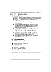
.... 1.2 PACKAGE CHECKLIST HDD Cable X 1 (optional) Serial ATA Cable X 2 Rear I/O Panel for choosing our product. CHAPTER 1: INTRODUCTION G41D3+/G41D3G+ 1.1 BEFORE YOU START Thank you take the motherboard out from anti-static bag, ground yourself properly by touching any unfastened small parts ...the computer from power outlet before operation. „ Before you for ATX Case X 1 Installation Guide X 1 Fully Setup Driver CD X 1 (full version manual files inside) FDD Cable X 1 (optional) USB 2.0 Cable X1 (optional) Serial ATA Power Cable X 1 (optional) Note: The package contents may be...
.... 1.2 PACKAGE CHECKLIST HDD Cable X 1 (optional) Serial ATA Cable X 2 Rear I/O Panel for choosing our product. CHAPTER 1: INTRODUCTION G41D3+/G41D3G+ 1.1 BEFORE YOU START Thank you take the motherboard out from anti-static bag, ground yourself properly by touching any unfastened small parts ...the computer from power outlet before operation. „ Before you for ATX Case X 1 Installation Guide X 1 Fully Setup Driver CD X 1 (full version manual files inside) FDD Cable X 1 (optional) USB 2.0 Cable X1 (optional) Serial ATA Power Cable X 1 (optional) Note: The package contents may be...
Setup Manual
Page 4
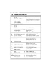
... rates up to RS-232 Port IDE Connector 2 x1 Each connector supports 2 IDE device SATA Version 2.0 specification compliant Realtek RTL 8103EL (G41D3+) LAN Realtek RTL 8111DL (G41D3G+) 10 / 100 Mb/s auto negotiation 10 / 100 Mb/s / 1Gb/s auto negotiation Sound Codec ALC662... Connector Serial Port Connector x1 Each connector supports 2 Floppy drives x1 Each connector supports 1 Printer port x1 Connects to 3.0 Gb/s. Motherboard Manual 1.3 MOTHERBOARD FEATURES SPEC LGA 775 Supports Hyper-Threading / Execute Disable Bit / Intel Core2Duo / Core2Quad / Enhanced Intel SpeedStep® / ...
... rates up to RS-232 Port IDE Connector 2 x1 Each connector supports 2 IDE device SATA Version 2.0 specification compliant Realtek RTL 8103EL (G41D3+) LAN Realtek RTL 8111DL (G41D3G+) 10 / 100 Mb/s auto negotiation 10 / 100 Mb/s / 1Gb/s auto negotiation Sound Codec ALC662... Connector Serial Port Connector x1 Each connector supports 2 Floppy drives x1 Each connector supports 1 Printer port x1 Connects to 3.0 Gb/s. Motherboard Manual 1.3 MOTHERBOARD FEATURES SPEC LGA 775 Supports Hyper-Threading / Execute Disable Bit / Intel Core2Duo / Core2Quad / Enhanced Intel SpeedStep® / ...

Setup Manual
Page 6
Motherboard Manual 1.5 MOTHERBOARD LAYOUT KBMS1 ATXPWR2 LGA775 CPU1 AT XPW R 1 DDR3 _A 1 DDR3 _B 1 V GA1 USB 1 CPU _FAN1 JUSBV1 RJ45USB1 Intel G41 IDE1 B IOS AU DIO1 F_AUDIO1 LAN BAT TERY PEX16_1 Super I/O Codec PCI1 Intel PCI2 ICH7 F_USB1 J_PRIN T1 J _COM1 FDD1 SYS_FAN1 J USBV2 F_USB2 PAN EL1 JCMOS1 SATA1 S ATA2 S ATA4 S ATA3 Note: ■ represents the 1st pin. 4
Motherboard Manual 1.5 MOTHERBOARD LAYOUT KBMS1 ATXPWR2 LGA775 CPU1 AT XPW R 1 DDR3 _A 1 DDR3 _B 1 V GA1 USB 1 CPU _FAN1 JUSBV1 RJ45USB1 Intel G41 IDE1 B IOS AU DIO1 F_AUDIO1 LAN BAT TERY PEX16_1 Super I/O Codec PCI1 Intel PCI2 ICH7 F_USB1 J_PRIN T1 J _COM1 FDD1 SYS_FAN1 J USBV2 F_USB2 PAN EL1 JCMOS1 SATA1 S ATA2 S ATA4 S ATA3 Note: ■ represents the 1st pin. 4

Setup Manual
Page 8
Step 4: Put the CPU Fan and heatsink assembly on the CPU and buckle it on CPU should point forwards this triangular cut edge. This completes the installation. 6 Step 2-1: Step 2-2: Step 3: Hold the CPU down firmly, and then lower the lever to locked position to complete the installation. Connect the CPU FAN power cable into the CPU_FAN1. The CPU will fit only in the correct orientation. Motherboard Manual Step 2: Look for the triangular cut edge on socket, and the golden dot on the retention frame.
Step 4: Put the CPU Fan and heatsink assembly on the CPU and buckle it on CPU should point forwards this triangular cut edge. This completes the installation. 6 Step 2-1: Step 2-2: Step 3: Hold the CPU down firmly, and then lower the lever to locked position to complete the installation. Connect the CPU FAN power cable into the CPU_FAN1. The CPU will fit only in the correct orientation. Motherboard Manual Step 2: Look for the triangular cut edge on socket, and the golden dot on the retention frame.

Setup Manual
Page 10
DDR3 module 1. DDR3_A1 DDR3_B1 Motherboard Manual 2.3 INSTALLING SYSTEM MEMORY A. Insert the DIMM vertically and firmly into the slot until the retaining chip snap back in place and the DIMM is properly seated. 8 Unlock a DIMM slot by pressing the retaining clips outward. Align a DIMM on the slot such that the notch on the DIMM matches the break on the Slot. 2.
DDR3 module 1. DDR3_A1 DDR3_B1 Motherboard Manual 2.3 INSTALLING SYSTEM MEMORY A. Insert the DIMM vertically and firmly into the slot until the retaining chip snap back in place and the DIMM is properly seated. 8 Unlock a DIMM slot by pressing the retaining clips outward. Align a DIMM on the slot such that the notch on the DIMM matches the break on the Slot. 2.

Setup Manual
Page 12
The IDE connector can connect a master and a slave drive, so you can connect up to two hard disk drives. 40 39 2 1 10 This connector supports the provided floppy drive ribbon cables. 2 34 1 33 IDE1: Hard Disk Connector The motherboard has a 32-bit Enhanced PCI IDE Controller that supports 360K, 720K, 1.2M, 1.44M and 2.88M floppy disk types. Motherboard Manual 2.4 CONNECTORS AND SLOTS FDD1: Floppy Disk Connector The motherboard provides a standard floppy disk connector that provides PIO Mode 0~4, Bus Master, and Ultra DMA 33/66/100 functionality.
The IDE connector can connect a master and a slave drive, so you can connect up to two hard disk drives. 40 39 2 1 10 This connector supports the provided floppy drive ribbon cables. 2 34 1 33 IDE1: Hard Disk Connector The motherboard has a 32-bit Enhanced PCI IDE Controller that supports 360K, 720K, 1.2M, 1.44M and 2.88M floppy disk types. Motherboard Manual 2.4 CONNECTORS AND SLOTS FDD1: Floppy Disk Connector The motherboard provides a standard floppy disk connector that provides PIO Mode 0~4, Bus Master, and Ultra DMA 33/66/100 functionality.
Setup Manual
Page 14
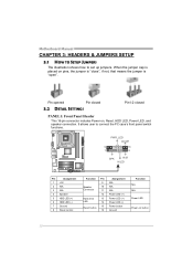
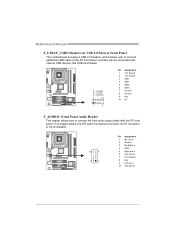
... Power-on pins, the jumper is "close", if not, that means the jumper is placed on , Reset, HDD LED, Power LED, and speaker connection. Motherboard Manual CHAPTER 3: HEADERS & JUMPERS SETUP 3.1 HOW TO SETUP JUMPERS The illustration shows how to connect the PC case's front panel switch functions. - It allows user to...
... Power-on pins, the jumper is "close", if not, that means the jumper is placed on , Reset, HDD LED, Power LED, and speaker connection. Motherboard Manual CHAPTER 3: HEADERS & JUMPERS SETUP 3.1 HOW TO SETUP JUMPERS The illustration shows how to connect the PC case's front panel switch functions. - It allows user to...
Setup Manual
Page 16
... This header allows user to connect additional USB cable on the PC front panel, and also can be connected with the PC front panel. Motherboard Manual F_USB1/F_USB2: Headers for USB 2.0 Ports at Front Panel This motherboard provides 2 USB 2.0 headers, which allows user to connect the front audio output cable with...
... This header allows user to connect additional USB cable on the PC front panel, and also can be connected with the PC front panel. Motherboard Manual F_USB1/F_USB2: Headers for USB 2.0 Ports at Front Panel This motherboard provides 2 USB 2.0 headers, which allows user to connect the front audio output cable with...
Setup Manual
Page 18
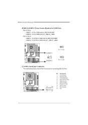
... port Connector The motherboard has a Serial Port Connector for USB ports at USB1/RJ45USB1. Pin 2-3 Close: JUSBV1: +5V STB for connecting RS-232 Port. Motherboard Manual JUSBV1/JUSBV2: Power Source Headers for USB Ports Pin 1-2 Close: JUSBV1: +5V for USB ports at F_USB1/F_USB2. JUSBV2: +5V STB for USB ports at...
... port Connector The motherboard has a Serial Port Connector for USB ports at USB1/RJ45USB1. Pin 2-3 Close: JUSBV1: +5V STB for connecting RS-232 Port. Motherboard Manual JUSBV1/JUSBV2: Power Source Headers for USB Ports Pin 1-2 Close: JUSBV1: +5V for USB ports at F_USB1/F_USB2. JUSBV2: +5V STB for USB ports at...

Setup Manual
Page 20
... driver, please click on the Software icon. Software Installation To install the software, please click on the Driver icon. Click on the Manual icon to browse for your optical drive. B. The setup guide will see the following window after you insert the CD The setup guide... will auto detect your motherboard and operating system. Motherboard Manual CHAPTER 4: USEFUL HELP 4.1 DRIVER INSTALLATION NOTE After you installed your operating system, please insert the Fully Setup Driver CD into your system, ...
... driver, please click on the Software icon. Software Installation To install the software, please click on the Driver icon. Click on the Manual icon to browse for your optical drive. B. The setup guide will see the following window after you insert the CD The setup guide... will auto detect your motherboard and operating system. Motherboard Manual CHAPTER 4: USEFUL HELP 4.1 DRIVER INSTALLATION NOTE After you installed your operating system, please insert the Fully Setup Driver CD into your system, ...

Setup Manual
Page 22
... to save this information, click "Send" to send the mail out. click "Send" to confirm or "Do Not Send" to the following web http://www.biostar.com.tw/app/en-us/about/contact.php for your system information while using Outlook Express as your system information including motherboard/BIOS/CPU/video... file name. Go to cancel. A warning dialog would appear asking for getting our contact information. 20 Enter the file name and then click "Save". Motherboard Manual After filling up this information to a .txt file, click "Save As..."
... to save this information, click "Send" to send the mail out. click "Send" to confirm or "Do Not Send" to the following web http://www.biostar.com.tw/app/en-us/about/contact.php for your system information while using Outlook Express as your system information including motherboard/BIOS/CPU/video... file name. Go to cancel. A warning dialog would appear asking for getting our contact information. 20 Enter the file name and then click "Save". Motherboard Manual After filling up this information to a .txt file, click "Save As..."
Setup Manual
Page 24
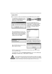
Motherboard Manual Before doing this process. Click Yes for requesting the BIOS file which is going to be run with the proper BIOS file, and this process ... function, so please check on board may take minutes. While the system boots up and the full screen logo shows, press key to skip this manual. 22 BIOS Update is being continuously updated.
Motherboard Manual Before doing this process. Click Yes for requesting the BIOS file which is going to be run with the proper BIOS file, and this process ... function, so please check on board may take minutes. While the system boots up and the full screen logo shows, press key to skip this manual. 22 BIOS Update is being continuously updated.
Setup Manual
Page 26
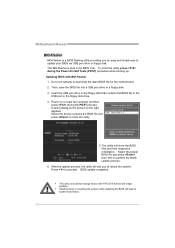
... completes. z This utility only allows storage device with BIO-Flasher 1. To enter the utility, press during the POST process. Power on the right appears. Motherboard Manual BIO-Flasher BIO-Flasher is built in the BIOS chip. A select dialog as the picture on or reset the computer and then press during the...
... completes. z This utility only allows storage device with BIO-Flasher 1. To enter the utility, press during the POST process. Power on the right appears. Motherboard Manual BIO-Flasher BIO-Flasher is built in the BIOS chip. A select dialog as the picture on or reset the computer and then press during the...
Setup Manual
Page 28
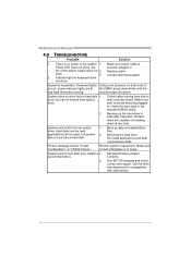
... system. 1. Screen message shows "Invalid Configuration" or "CMOS Failure." second hard drive. 2. Contact technical support. 2. drive, but system 2. System cannot boot after user installs a 1. Motherboard Manual 4.5 TROUBLESHOOTING Probable Solution 1. Keyboard lights Using even pressure on both ends are capable of the power supply does not 2. Reformat the hard drive. Re-install...
... system. 1. Screen message shows "Invalid Configuration" or "CMOS Failure." second hard drive. 2. Contact technical support. 2. drive, but system 2. System cannot boot after user installs a 1. Motherboard Manual 4.5 TROUBLESHOOTING Probable Solution 1. Keyboard lights Using even pressure on both ends are capable of the power supply does not 2. Reformat the hard drive. Re-install...

