
Setup Manual
Page 2
Table of Contents Chapter 1: Introduction 1 1.1 Before You Start 1 1.2 Package Checklist 1 1.3 Motherboard Features 2 1.4 Rear Panel Connectors 3 1.5 Motherboard Layout 4 Chapter 2: Hardware Installation 5 2.1 Installing Central Processing Unit (CPU 5 2.2 FAN Headers 7 2.3 Installing System Memory 8 2.4 Connectors and Slots 10 Chapter 3: Headers & Jumpers Setup 13 3.1 How to ...
Table of Contents Chapter 1: Introduction 1 1.1 Before You Start 1 1.2 Package Checklist 1 1.3 Motherboard Features 2 1.4 Rear Panel Connectors 3 1.5 Motherboard Layout 4 Chapter 2: Hardware Installation 5 2.1 Installing Central Processing Unit (CPU 5 2.2 FAN Headers 7 2.3 Installing System Memory 8 2.4 Connectors and Slots 10 Chapter 3: Headers & Jumpers Setup 13 3.1 How to ...

Setup Manual
Page 3
.... 1.2 PACKAGE CHECKLIST HDD Cable X 1 Serial ATA Cable X 1 Rear I/O Panel for choosing our product. Before you start installing the motherboard, please make sure you follow the instructions below: „ Prepare a dry and stable working environment with sufficient lighting. „ Always disconnect...the static charge. „ Avoid touching the components on motherboard or the rear side of the computer should be 0 to area or your motherboard version. 1 CHAPTER 1: INTRODUCTION G41 DVI 1.1 BEFORE YOU START Thank you take the motherboard out from dangerous area, such as heat source, humid...
.... 1.2 PACKAGE CHECKLIST HDD Cable X 1 Serial ATA Cable X 1 Rear I/O Panel for choosing our product. Before you start installing the motherboard, please make sure you follow the instructions below: „ Prepare a dry and stable working environment with sufficient lighting. „ Always disconnect...the static charge. „ Avoid touching the components on motherboard or the rear side of the computer should be 0 to area or your motherboard version. 1 CHAPTER 1: INTRODUCTION G41 DVI 1.1 BEFORE YOU START Thank you take the motherboard out from dangerous area, such as heat source, humid...

Setup Manual
Page 4
... device x4 Each connector supports 1 SATA devices x1 Supports front panel facilities 2 Motherboard Manual 1.3 MOTHERBOARD FEATURES SPEC LGA 775 Supports Hyper-Threading / Execute Disable Bit / Intel Core2Duo .../ Core2Quad / Enhanced Intel SpeedStep® / Intel Architecture-64 / CPU Pentium Dual-Core / Celeron Dual-Core / Extended Memory 64 Technology / Virtualization Celeron 4xx processor Technology (Maximum Watt: 95W) FSB Support 800 / 1066 / 1333 MHz Chipset Intel G41...
... device x4 Each connector supports 1 SATA devices x1 Supports front panel facilities 2 Motherboard Manual 1.3 MOTHERBOARD FEATURES SPEC LGA 775 Supports Hyper-Threading / Execute Disable Bit / Intel Core2Duo .../ Core2Quad / Enhanced Intel SpeedStep® / Intel Architecture-64 / CPU Pentium Dual-Core / Celeron Dual-Core / Extended Memory 64 Technology / Virtualization Celeron 4xx processor Technology (Maximum Watt: 95W) FSB Support 800 / 1066 / 1333 MHz Chipset Intel G41...

Setup Manual
Page 6
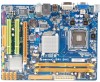
Motherboard Manual 1.5 MOTHERBOARD LAYOUT KBMS1 LGA775 VGA1 ATXPWR2 CPU1 CPU_FAN1 ATXPWR1 D D R 2_A 1 D D R 2_B 1 DVI1 JUSBV1 USB1 LAN RJ45USB1 Intel G41 IDE1 AUDIO1 F_AUDIO1 CD_IN1 BAT1 F_CO M 1 Super I/O SPDIF 1 PEX16_1 PCI1 Intel ICH7 Codec F_PRINT1 PCI2 FDD1 JUSBV2 SYS _FA N1 F_USB1 F_USB2 PANEL1 Note: ■ represents the 1st pin. J CM O S1 BI O S SATA4 SATA3 SATA2 SATA1 4
Motherboard Manual 1.5 MOTHERBOARD LAYOUT KBMS1 LGA775 VGA1 ATXPWR2 CPU1 CPU_FAN1 ATXPWR1 D D R 2_A 1 D D R 2_B 1 DVI1 JUSBV1 USB1 LAN RJ45USB1 Intel G41 IDE1 AUDIO1 F_AUDIO1 CD_IN1 BAT1 F_CO M 1 Super I/O SPDIF 1 PEX16_1 PCI1 Intel ICH7 Codec F_PRINT1 PCI2 FDD1 JUSBV2 SYS _FA N1 F_USB1 F_USB2 PANEL1 Note: ■ represents the 1st pin. J CM O S1 BI O S SATA4 SATA3 SATA2 SATA1 4

Setup Manual
Page 8
Motherboard Manual Step 2: Look for the triangular cut edge. This completes the installation. 6 Step 2-1: Step 2-2: Step 3: Hold the CPU down firmly, and then lower the lever to locked position to complete the installation. The CPU will fit only in the correct orientation. Connect the CPU FAN power cable into the CPU_FAN1. Step 4: Put the CPU Fan and heatsink assembly on the CPU and buckle it on CPU should point forwards this triangular cut edge on socket, and the golden dot on the retention frame.
Motherboard Manual Step 2: Look for the triangular cut edge. This completes the installation. 6 Step 2-1: Step 2-2: Step 3: Hold the CPU down firmly, and then lower the lever to locked position to complete the installation. The CPU will fit only in the correct orientation. Connect the CPU FAN power cable into the CPU_FAN1. Step 4: Put the CPU Fan and heatsink assembly on the CPU and buckle it on CPU should point forwards this triangular cut edge on socket, and the golden dot on the retention frame.

Setup Manual
Page 10
Unlock a DIMM slot by pressing the retaining clips outward. Align a DIMM on the slot such that the notch on the DIMM matches the break on the Slot. 2. Insert the DIMM vertically and firmly into the slot until the retaining chip snap back in place and the DIMM is properly seated. 8 DDR2 module 1. DD R2_A1 DD R2_B1 Motherboard Manual 2.3 INSTALLING SYSTEM MEMORY A.
Unlock a DIMM slot by pressing the retaining clips outward. Align a DIMM on the slot such that the notch on the DIMM matches the break on the Slot. 2. Insert the DIMM vertically and firmly into the slot until the retaining chip snap back in place and the DIMM is properly seated. 8 DDR2 module 1. DD R2_A1 DD R2_B1 Motherboard Manual 2.3 INSTALLING SYSTEM MEMORY A.

Setup Manual
Page 12
... floppy disk connector that supports 360K, 720K, 1.2M, 1.44M and 2.88M floppy disk types. 2 34 1 33 IDE1: Hard Disk Connector The motherboard has a 32-bit Enhanced PCI IDE Controller that provides PIO Mode 0~4, Bus Master, and Ultra DMA 33/66/100 functionality. 40 39 2 1 ...SATA1~SATA4: Serial ATA Connectors The motherboard has a PCI to SATA Controller with 4channels SATA interface, it satisfies the SATA 2.0 spec and with transfer rate of 3Gb/s. SATA 4 SATA 3 SATA ...
... floppy disk connector that supports 360K, 720K, 1.2M, 1.44M and 2.88M floppy disk types. 2 34 1 33 IDE1: Hard Disk Connector The motherboard has a 32-bit Enhanced PCI IDE Controller that provides PIO Mode 0~4, Bus Master, and Ultra DMA 33/66/100 functionality. 40 39 2 1 ...SATA1~SATA4: Serial ATA Connectors The motherboard has a PCI to SATA Controller with 4channels SATA interface, it satisfies the SATA 2.0 spec and with transfer rate of 3Gb/s. SATA 4 SATA 3 SATA ...

Setup Manual
Page 14
PCI stands for Peripheral Component Interconnect, and it is designated as 32 bits. P CI1 P CI2 12 Motherboard Manual PEX16_1: PCI-Express x16 Slot - This PCI slot is a bus standard for an aggregate of 8GB/s totally. - Maximum theoretical realized... bandwidth of 2.5Gb/s on the data pins. - 2X bandwidth over the traditional PCI architecture. PEX16_1 PCI1/PCI2: Peripheral Component Interconnect Slots This motherboard is equipped with 2 standard PCI slots. PCI-Express 1.0a compliant. - PCI-Express supports a raw bit-rate of 4GB/s simultaneously per direction, for expansion...
PCI stands for Peripheral Component Interconnect, and it is designated as 32 bits. P CI1 P CI2 12 Motherboard Manual PEX16_1: PCI-Express x16 Slot - This PCI slot is a bus standard for an aggregate of 8GB/s totally. - Maximum theoretical realized... bandwidth of 2.5Gb/s on the data pins. - 2X bandwidth over the traditional PCI architecture. PEX16_1 PCI1/PCI2: Peripheral Component Interconnect Slots This motherboard is equipped with 2 standard PCI slots. PCI-Express 1.0a compliant. - PCI-Express supports a raw bit-rate of 4GB/s simultaneously per direction, for expansion...

Setup Manual
Page 16
.../F_USB2: Headers for five seconds. 4. Remove AC power line. 2. Set the jumper to "Pin 2-3 close ". 5. Set the jumper to avoid damaging the motherboard. 13 Pin 1-2 Close: Normal Operation (Default). 13 13 Pin 2-3 Close: Clear CMOS data. ※ Clear CMOS Procedures: 1. F_USB1 F_USB2 2 10 1 9 Pin Assignment... "Pin 1-2 close ". 3. Reset your desired password or clear the CMOS data. 14 Wait for USB 2.0 Ports at Front Panel This motherboard provides 2 USB 2.0 headers, which allows user to connect additional USB cable on pin2-3 allows user to restore the BIOS safe setting and ...
.../F_USB2: Headers for five seconds. 4. Remove AC power line. 2. Set the jumper to "Pin 2-3 close ". 5. Set the jumper to avoid damaging the motherboard. 13 Pin 1-2 Close: Normal Operation (Default). 13 13 Pin 2-3 Close: Clear CMOS data. ※ Clear CMOS Procedures: 1. F_USB1 F_USB2 2 10 1 9 Pin Assignment... "Pin 1-2 close ". 3. Reset your desired password or clear the CMOS data. 14 Wait for USB 2.0 Ports at Front Panel This motherboard provides 2 USB 2.0 headers, which allows user to connect additional USB cable on pin2-3 allows user to restore the BIOS safe setting and ...

Setup Manual
Page 18
Motherboard Manual JUSBV1/JUSBV2: Power Source Headers for USB Ports Pin 1-2 Close: JUSBV1: +5V for USB ports at USB1/RJ45USB1. Pin 2-3 Close: JUSBV1: +5V STB for ... 7 Request to send 8 Clear to send 9 Ring indicator 10 Key 16 JUSBV1 3 1 13 JUSBV2 13 Pin 1-2 close 13 Pin 2-3 close F_COM1: Serial port Connector The motherboard has a Serial Port Connector for USB ports at F_USB1/F_USB2. JUSBV2: +5V STB for USB ports at F_USB1/F_USB2.
Motherboard Manual JUSBV1/JUSBV2: Power Source Headers for USB Ports Pin 1-2 Close: JUSBV1: +5V for USB ports at USB1/RJ45USB1. Pin 2-3 Close: JUSBV1: +5V STB for ... 7 Request to send 8 Clear to send 9 Ring indicator 10 Key 16 JUSBV1 3 1 13 JUSBV2 13 Pin 1-2 close 13 Pin 2-3 close F_COM1: Serial port Connector The motherboard has a Serial Port Connector for USB ports at F_USB1/F_USB2. JUSBV2: +5V STB for USB ports at F_USB1/F_USB2.

Setup Manual
Page 20
... You will list the compatible driver for better system performance. Driver Installation To install the driver, please click on the Software icon. C. Motherboard Manual CHAPTER 4: USEFUL HELP 4.1 DRIVER INSTALLATION NOTE After you installed your operating system, please insert the Fully Setup Driver CD into your ...optical drive and install the driver for your motherboard and operating system. You will see the following window after you insert the Driver CD, please use file browser to launch the ...
... You will list the compatible driver for better system performance. Driver Installation To install the driver, please click on the Software icon. C. Motherboard Manual CHAPTER 4: USEFUL HELP 4.1 DRIVER INSTALLATION NOTE After you installed your operating system, please insert the Fully Setup Driver CD into your ...optical drive and install the driver for your motherboard and operating system. You will see the following window after you insert the Driver CD, please use file browser to launch the ...

Setup Manual
Page 22
... saved .txt file, you are not using eHot-Line service. If you will be saved to a .txt file. Go to the following web http://www.biostar.com.tw/app/en-us/about/contact.php for your confirmation; If you may need to save this information, click "Send" to send the mail... share customer's data with other third parties, so please feel free to provide your system information while using Outlook Express as your system information including motherboard/BIOS/CPU/video/ device/OS information. click "Send" to confirm or "Do Not Send" to cancel. Enter the file name and then click "Save...
... saved .txt file, you are not using eHot-Line service. If you will be saved to a .txt file. Go to the following web http://www.biostar.com.tw/app/en-us/about/contact.php for your confirmation; If you may need to save this information, click "Send" to send the mail... share customer's data with other third parties, so please feel free to provide your system information while using Outlook Express as your system information including motherboard/BIOS/CPU/video/ device/OS information. click "Send" to confirm or "Do Not Send" to cancel. Enter the file name and then click "Save...

Setup Manual
Page 23
AWARD BIOS Show current BIOS information AMI BIOS Clear CMOS function (Only for AWARD BIOS) Save current BIOS to update your motherboard BIOS under Windows system. G41 DVI BIOS Update BIOS Update is a convenient utility which allows you to a .bin file Update BIOS with a BIOS file Once click on this button, the saving dialog will show. Choose the position to save file and enter file name. (We recommend that the file name should be English/number and no longer than 7 characters.) Then click Save. 21
AWARD BIOS Show current BIOS information AMI BIOS Clear CMOS function (Only for AWARD BIOS) Save current BIOS to update your motherboard BIOS under Windows system. G41 DVI BIOS Update BIOS Update is a convenient utility which allows you to a .bin file Update BIOS with a BIOS file Once click on this button, the saving dialog will show. Choose the position to save file and enter file name. (We recommend that the file name should be English/number and no longer than 7 characters.) Then click Save. 21

Setup Manual
Page 24
.... For better performance, the software is completed. Then click Update BIOS button, a dialog will update BIOS with Clear CMOS function, so please check on Open. Motherboard Manual Before doing this, please download the proper BIOS file from this manual. 22 For AWARD BIOS, update BIOS procedure should be run with the...
.... For better performance, the software is completed. Then click Update BIOS button, a dialog will update BIOS with Clear CMOS function, so please check on Open. Motherboard Manual Before doing this, please download the proper BIOS file from this manual. 22 For AWARD BIOS, update BIOS procedure should be run with the...

Setup Manual
Page 25
.... (See "Close CMOS Header: JCMOS1" section) 2. Wait for seconds. 2. CPU fan is over heated, the motherboard will shutdown automatically to relief the CPU protection function. 1. Plug in the power cord and boot up the system. G41 DVI 4.3 EXTRA INFORMATION CPU Overheated If the system shutdown automatically after power on system for seconds. 3. After...
.... (See "Close CMOS Header: JCMOS1" section) 2. Wait for seconds. 2. CPU fan is over heated, the motherboard will shutdown automatically to relief the CPU protection function. 1. Plug in the power cord and boot up the system. G41 DVI 4.3 EXTRA INFORMATION CPU Overheated If the system shutdown automatically after power on system for seconds. 3. After...

Setup Manual
Page 26
Motherboard Manual BIO-Flasher BIO-Flasher is built in the BIOS chip. Select the proper BIOS file and press then to proceed. Press to perform the ... file into a USB pen drive or a floppy disk. 3. Select the device contains the BIOS file and press to download the latest BIOS file for the motherboard. 2. BIOS update completes. After the update process, the utility will lead to update your BIOS via USB pen drive or floppy disk. z Shutting down or...
Motherboard Manual BIO-Flasher BIO-Flasher is built in the BIOS chip. Select the proper BIOS file and press then to proceed. Press to perform the ... file into a USB pen drive or a floppy disk. 3. Select the device contains the BIOS file and press to download the latest BIOS file for the motherboard. 2. BIOS update completes. After the update process, the utility will lead to update your BIOS via USB pen drive or floppy disk. z Shutting down or...

Setup Manual
Page 27
Before declaring the motherboard beyond all other expansion cards are absent, consult your system manufacturer. Remove all other expansion 6, 7 cards are absent, one at a time until the problem happens ... faulty. 25 Insert the cards back into the system one of the add-in card, replace or 8 reseat the video adapter. 4.4 AMI BIOS BEEP CODE G41 DVI Boot Block Beep Codes Number of Beeps Description 1 No media present. (Insert diskette in floppy drive A:) 2 "AMIBOOT.ROM" file not found in root directory of...
Before declaring the motherboard beyond all other expansion cards are absent, consult your system manufacturer. Remove all other expansion 6, 7 cards are absent, one at a time until the problem happens ... faulty. 25 Insert the cards back into the system one of the add-in card, replace or 8 reseat the video adapter. 4.4 AMI BIOS BEEP CODE G41 DVI Boot Block Beep Codes Number of Beeps Description 1 No media present. (Insert diskette in floppy drive A:) 2 "AMIBOOT.ROM" file not found in root directory of...

Setup Manual
Page 28
... does not 2. fails to disk controller board. Review system's equipment. There is in the standard CMOS setup. 2. Re-install applications and data using backup disks. Motherboard Manual 4.5 TROUBLESHOOTING Probable Solution 1.
... does not 2. fails to disk controller board. Review system's equipment. There is in the standard CMOS setup. 2. Re-install applications and data using backup disks. Motherboard Manual 4.5 TROUBLESHOOTING Probable Solution 1.

Bios Setup
Page 2
... implemented via the System Management Int errupt (SMI). Basic Input-Output System (BIOS) determines what a computer can also be managed by this motherboard. EPA Green PC Support T his system controls most of Advanced Configuration and Power interface specifi cation (ACPI). BIOS activates at the first stag... Support T his AMI BIOS supports the Plug and Play Version 1.0A specification. Sleep and Suspend power man agement modes are supported. G41 DVI BIOS Manual BIOS Setup Introduction T he power of CMOS RAM is supplied by a battery so that it retains theSetup information when the...
... implemented via the System Management Int errupt (SMI). Basic Input-Output System (BIOS) determines what a computer can also be managed by this motherboard. EPA Green PC Support T his system controls most of Advanced Configuration and Power interface specifi cation (ACPI). BIOS activates at the first stag... Support T his AMI BIOS supports the Plug and Play Version 1.0A specification. Sleep and Suspend power man agement modes are supported. G41 DVI BIOS Manual BIOS Setup Introduction T he power of CMOS RAM is supplied by a battery so that it retains theSetup information when the...

Bios Setup
Page 3
... board may be slightly different from this manual is providing a brief description of the motherboard. z For better system perform ance, the BIOS firmware is supported. T he default BIOS settings apply for that may be caused by wrong-settings. 2 G41 DVI BIOS Manual PCI Bus Support T his AMI BIOS supports the Intel CPU. Supported...
... board may be slightly different from this manual is providing a brief description of the motherboard. z For better system perform ance, the BIOS firmware is supported. T he default BIOS settings apply for that may be caused by wrong-settings. 2 G41 DVI BIOS Manual PCI Bus Support T his AMI BIOS supports the Intel CPU. Supported...

