Setup Manual
Page 2
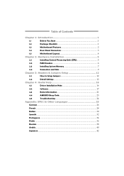
Table of Contents Chapter 1: Introduction 1 1.1 Before You Start 1 1.2 Package Checklist 1 1.3 Motherboard Features 2 1.4 Rear Panel Connectors 3 1.5 Motherboard Layout 4 Chapter 2: Hardware Installation 5 2.1 Installing Central Processing Unit (CPU 5 2.2 FAN Headers 6 2.3 Installing System Memory 7 2.4 Connectors and Slots 9 Chapter 3: Headers & Jumpers Setup 12 3.1 How to Setup ...
Table of Contents Chapter 1: Introduction 1 1.1 Before You Start 1 1.2 Package Checklist 1 1.3 Motherboard Features 2 1.4 Rear Panel Connectors 3 1.5 Motherboard Layout 4 Chapter 2: Hardware Installation 5 2.1 Installing Central Processing Unit (CPU 5 2.2 FAN Headers 6 2.3 Installing System Memory 7 2.4 Connectors and Slots 9 Chapter 3: Headers & Jumpers Setup 12 3.1 How to Setup ...
Setup Manual
Page 3
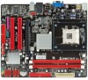
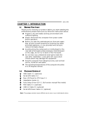
... remove the static charge. „ Avoid touching the components on motherboard or the rear side of the computer should be different due to area or your motherboard version. 1 Before you start installing the motherboard, please make sure you follow the instructions below: „ Prepare... X 1 Fully Setup Driver CD X 1 (full version manual files inside the case after installation. CHAPTER 1: INTRODUCTION G31-M4 1.1 BEFORE YOU START Thank you take the motherboard out from anti-static bag, ground yourself properly by touching any safely grounded appliance, or use grounded wrist strap to...
... remove the static charge. „ Avoid touching the components on motherboard or the rear side of the computer should be different due to area or your motherboard version. 1 Before you start installing the motherboard, please make sure you follow the instructions below: „ Prepare... X 1 Fully Setup Driver CD X 1 (full version manual files inside the case after installation. CHAPTER 1: INTRODUCTION G31-M4 1.1 BEFORE YOU START Thank you take the motherboard out from anti-static bag, ground yourself properly by touching any safely grounded appliance, or use grounded wrist strap to...
Setup Manual
Page 4
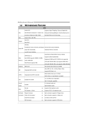
Motherboard Manual 1.3 MOTHERBOARD FEATURES SPEC Socket 478 Supports Hyper-Threading / Execute Disable Bit / CPU Intel Pentium4 /Celeron D / Celeron 3xx Enhanced Intel SpeedStep® / Intel Architecture-64 / processors (Maximum Watt: 95W) Extended Memory 64 Technology FSB Support 800 / 533 MHz Chipset Intel G31 Intel ICH7 ITE 8721 Super I/O Provides the most commonly used legacy Environment...
Motherboard Manual 1.3 MOTHERBOARD FEATURES SPEC Socket 478 Supports Hyper-Threading / Execute Disable Bit / CPU Intel Pentium4 /Celeron D / Celeron 3xx Enhanced Intel SpeedStep® / Intel Architecture-64 / processors (Maximum Watt: 95W) Extended Memory 64 Technology FSB Support 800 / 533 MHz Chipset Intel G31 Intel ICH7 ITE 8721 Super I/O Provides the most commonly used legacy Environment...
Setup Manual
Page 6
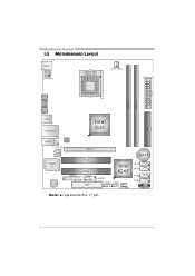
Motherboard Manual 1.5 MOTHERBOARD LAYOUT KB MS1 ATXP W R2 Socket 478 CPU_FAN1 ATXPWR1 DDR 2_A1 DDR 2_B1 VGA1 ID E1 USB 2 RJ 45US B1 Intel G31 AUDIO1 BIOS F_AUDIOF1 LAN PEX16_1 Super I/O Codec JPRNT1 PCI1 PCI2 JCOM1 FDD1 Intel ICH7 JCMOS1 F_USB1 F_USB2 SYS_FAN1 Note: ■ represents the 1st pin. BAT1 SATA4 SATA3 SATA2 SATA1 PANEL1 4
Motherboard Manual 1.5 MOTHERBOARD LAYOUT KB MS1 ATXP W R2 Socket 478 CPU_FAN1 ATXPWR1 DDR 2_A1 DDR 2_B1 VGA1 ID E1 USB 2 RJ 45US B1 Intel G31 AUDIO1 BIOS F_AUDIOF1 LAN PEX16_1 Super I/O Codec JPRNT1 PCI1 PCI2 JCOM1 FDD1 Intel ICH7 JCMOS1 F_USB1 F_USB2 SYS_FAN1 Note: ■ represents the 1st pin. BAT1 SATA4 SATA3 SATA2 SATA1 PANEL1 4
Setup Manual
Page 8
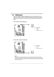
Motherboard Manual 2.2 FAN HEADERS These fan headers support cooling-fans built in the computer. The fan cable and connector may be connected to GND. 6 Connect the ...
Motherboard Manual 2.2 FAN HEADERS These fan headers support cooling-fans built in the computer. The fan cable and connector may be connected to GND. 6 Connect the ...
Setup Manual
Page 10
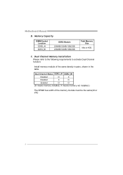
Motherboard Manual B. Memory Capacity DIMM Socket Location DDR2_A1 DDR2_B1 DDR2 Module 256MB/512MB/1GB/2GB 256MB/512MB/1GB/2GB Total Memory Size Max is 4GB. Dual Channel Memory Installation Please refer to the following requirements to activate Dual Channel function: Install memory module of the memory module must be the same(x8 or x16) 8 C. Dual Channel Status DDR2_A1 DDR2_B1 Disabled O X Disabled X O Enabled O O (O means memory installed, X means memory not installed.) The DRAM bus width of the same density in pairs, shown in the table.
Motherboard Manual B. Memory Capacity DIMM Socket Location DDR2_A1 DDR2_B1 DDR2 Module 256MB/512MB/1GB/2GB 256MB/512MB/1GB/2GB Total Memory Size Max is 4GB. Dual Channel Memory Installation Please refer to the following requirements to activate Dual Channel function: Install memory module of the memory module must be the same(x8 or x16) 8 C. Dual Channel Status DDR2_A1 DDR2_B1 Disabled O X Disabled X O Enabled O O (O means memory installed, X means memory not installed.) The DRAM bus width of the same density in pairs, shown in the table.
Setup Manual
Page 11
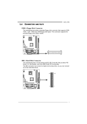
The IDE connector can connect a master and a slave drive, so you can connect up to two hard disk drives. 40 39 2 1 9 This connector supports the provided floppy drive ribbon cables. 2 34 1 33 IDE1: Hard Disk Connector The motherboard has a 32-bit Enhanced PCI IDE Controller that supports 360K, 720K, 1.2M, 1.44M and 2.88M floppy disk types. 2.4 CONNECTORS AND SLOTS G31-M4 FDD1: Floppy Disk Connector The motherboard provides a standard floppy disk connector that provides PIO Mode 0~4, Bus Master, and Ultra DMA 33/66/100 functionality.
The IDE connector can connect a master and a slave drive, so you can connect up to two hard disk drives. 40 39 2 1 9 This connector supports the provided floppy drive ribbon cables. 2 34 1 33 IDE1: Hard Disk Connector The motherboard has a 32-bit Enhanced PCI IDE Controller that supports 360K, 720K, 1.2M, 1.44M and 2.88M floppy disk types. 2.4 CONNECTORS AND SLOTS G31-M4 FDD1: Floppy Disk Connector The motherboard provides a standard floppy disk connector that provides PIO Mode 0~4, Bus Master, and Ultra DMA 33/66/100 functionality.
Setup Manual
Page 12
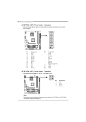
Motherboard Manual ATXPWR1: ATX Power Source Connector This connector allows user to connect 24-pin power connector on the ATX power supply. 12 24 1 13 Pin ...
Motherboard Manual ATXPWR1: ATX Power Source Connector This connector allows user to connect 24-pin power connector on the ATX power supply. 12 24 1 13 Pin ...
Setup Manual
Page 13
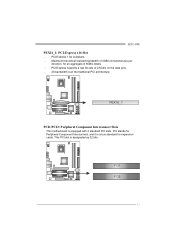
PEX16_1 PCI1/PCI2: Peripheral Component Interconnect Slots This motherboard is a bus standard for expansion cards. PCI stands for an aggregate of 2.5Gb/s on the data pins. - 2X bandwidth over the traditional PCI architecture. This PCI slot is designated as 32 bits. PCI1 PCI2 11 Maximum theoretical realized bandwidth of 4GB/s simultaneously per direction, for Peripheral Component Interconnect, and it is equipped with 2 standard PCI slots. PCI-Express supports a raw bit-rate of 8GB/s totally. - PCI-Express 1.0a compliant. - G31-M4 PEX16_1: PCI-Express x16 Slot -
PEX16_1 PCI1/PCI2: Peripheral Component Interconnect Slots This motherboard is a bus standard for expansion cards. PCI stands for an aggregate of 2.5Gb/s on the data pins. - 2X bandwidth over the traditional PCI architecture. This PCI slot is designated as 32 bits. PCI1 PCI2 11 Maximum theoretical realized bandwidth of 4GB/s simultaneously per direction, for Peripheral Component Interconnect, and it is equipped with 2 standard PCI slots. PCI-Express supports a raw bit-rate of 8GB/s totally. - PCI-Express 1.0a compliant. - G31-M4 PEX16_1: PCI-Express x16 Slot -
Setup Manual
Page 14
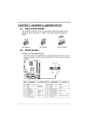
Motherboard Manual CHAPTER 3: HEADERS & JUMPERS SETUP 3.1 HOW TO SETUP JUMPERS The illustration shows how to connect the PC case's front panel switch functions. - When the jumper ...
Motherboard Manual CHAPTER 3: HEADERS & JUMPERS SETUP 3.1 HOW TO SETUP JUMPERS The illustration shows how to connect the PC case's front panel switch functions. - When the jumper ...
Setup Manual
Page 15
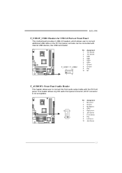
... to connect additional USB cable on the PC front panel, and also can be connected with the PC front panel. G31-M4 F_USB1/F_USB2: Headers for USB 2.0 Ports at Front Panel This motherboard provides 2 USB 2.0 headers, which allows user to connect the front audio output cable with internal USB devices, like USB card...
... to connect additional USB cable on the PC front panel, and also can be connected with the PC front panel. G31-M4 F_USB1/F_USB2: Headers for USB 2.0 Ports at Front Panel This motherboard provides 2 USB 2.0 headers, which allows user to connect the front audio output cable with internal USB devices, like USB card...
Setup Manual
Page 16
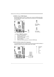
... follow the procedures to "Pin 2-3 close ". 5. SATA1~SATA4: Serial ATA Connectors The motherboard has a PCI to "Pin 1-2 close ". 3. Reset your desired password or clear the CMOS data. Motherboard Manual JCMOS1: Clear CMOS Header By placing the jumper on the AC. 6. Set the jumper... to avoid damaging the motherboard. 1 3 Pin 1-2 Close: Normal Operation (Default). 1 3 1 Pin 2-3 Close: 3 Clear CMOS data. ...
... follow the procedures to "Pin 2-3 close ". 5. SATA1~SATA4: Serial ATA Connectors The motherboard has a PCI to "Pin 1-2 close ". 3. Reset your desired password or clear the CMOS data. Motherboard Manual JCMOS1: Clear CMOS Header By placing the jumper on the AC. 6. Set the jumper... to avoid damaging the motherboard. 1 3 Pin 1-2 Close: Normal Operation (Default). 1 3 1 Pin 2-3 Close: 3 Clear CMOS data. ...
Setup Manual
Page 17
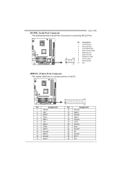
... 22 23 24 25 26 25 Assignment Ground Data 6 Ground Data 7 Ground -ACK Ground Busy Ground PE Ground SCLT Key 15 JCOM1: Serial Port Connector G31-M4 The motherboard has a Serial Port Connector for connecting RS-232 Port. Pin Assignment 1 Carrier detect 2 Received data 3 Transmitted data 4 Data terminal ready 5 Signal ground 6 Data set...
... 22 23 24 25 26 25 Assignment Ground Data 6 Ground Data 7 Ground -ACK Ground Busy Ground PE Ground SCLT Key 15 JCOM1: Serial Port Connector G31-M4 The motherboard has a Serial Port Connector for connecting RS-232 Port. Pin Assignment 1 Carrier detect 2 Received data 3 Transmitted data 4 Data terminal ready 5 Signal ground 6 Data set...
Setup Manual
Page 18
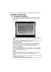
... 4: USEFUL HELP 4.1 DRIVER INSTALLATION NOTE After you insert the CD The setup guide will auto detect your motherboard and operating system. The setup guide will see the following window after you insert the Driver CD, please use file browser to launch the ..., please insert the Fully Setup Driver CD into your system, click on each software title to locate and execute the file SETUP.EXE under your motherboard and operating system. A. Click on each device driver to launch the installation program. C. Please download the latest version of Acrobat Reader software from the ...
... 4: USEFUL HELP 4.1 DRIVER INSTALLATION NOTE After you insert the CD The setup guide will auto detect your motherboard and operating system. The setup guide will see the following window after you insert the Driver CD, please use file browser to launch the ..., please insert the Fully Setup Driver CD into your system, click on each software title to locate and execute the file SETUP.EXE under your motherboard and operating system. A. Click on each device driver to launch the installation program. C. Please download the latest version of Acrobat Reader software from the ...
Setup Manual
Page 20
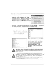
Motherboard Manual After filling up this information to send the mail out. If you want to save the system information to a .txt file and send the ... name and then click "Save". click "Send" to confirm or "Do Not Send" to the following web http://www.biostar.com.tw/app/en-us/about/contact.php for your system information including motherboard/BIOS/CPU/video/ device/OS information. Open the saved .txt file, you to a .txt file. A warning dialog would...
Motherboard Manual After filling up this information to send the mail out. If you want to save the system information to a .txt file and send the ... name and then click "Save". click "Send" to confirm or "Do Not Send" to the following web http://www.biostar.com.tw/app/en-us/about/contact.php for your system information including motherboard/BIOS/CPU/video/ device/OS information. Open the saved .txt file, you to a .txt file. A warning dialog would...
Setup Manual
Page 21
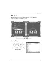
G31-M4 BIOS Update BIOS Update is a convenient utility which allows you to save file and enter file name. (We recommend that the file name should be English/number and no longer than 7 characters.) Then click Save. 19 Choose the position to update your motherboard BIOS under Windows system. AWARD BIOS Show current BIOS information AMI BIOS Clear CMOS function (Only for AWARD BIOS) Save current BIOS to a .bin file Update BIOS with a BIOS file Once click on this button, the saving dialog will show.
G31-M4 BIOS Update BIOS Update is a convenient utility which allows you to save file and enter file name. (We recommend that the file name should be English/number and no longer than 7 characters.) Then click Save. 19 Choose the position to update your motherboard BIOS under Windows system. AWARD BIOS Show current BIOS information AMI BIOS Clear CMOS function (Only for AWARD BIOS) Save current BIOS to a .bin file Update BIOS with a BIOS file Once click on this button, the saving dialog will show.
Setup Manual
Page 22
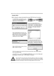
... up and the full screen logo shows, press key to restart the system. BIOS Update is being continuously updated. Click Yes for your reference only. Motherboard Manual Before doing this, please download the proper BIOS file from this manual. 20 Please do not open dialog will show for requesting the BIOS...
... up and the full screen logo shows, press key to restart the system. BIOS Update is being continuously updated. Click Yes for your reference only. Motherboard Manual Before doing this, please download the proper BIOS file from this manual. 20 Please do not open dialog will show for requesting the BIOS...
Setup Manual
Page 23
CPU fan is over heated, the motherboard will shutdown automatically to relief the CPU protection function. 1. Plug in the power cord and boot up the system. Wait for seconds. 3. Power on system ... double check: 1. Clear the CMOS data. (See "Close CMOS Header: JCMOS1" section) 2. Or you can: 1. The CPU cooler surface is fulfilling with the CPU surface. 2. G31-M4 4.3 EXTRA INFORMATION CPU Overheated If the system shutdown automatically after power on the system again. 21 CPU fan speed is placed evenly with the CPU...
CPU fan is over heated, the motherboard will shutdown automatically to relief the CPU protection function. 1. Plug in the power cord and boot up the system. Wait for seconds. 3. Power on system ... double check: 1. Clear the CMOS data. (See "Close CMOS Header: JCMOS1" section) 2. Or you can: 1. The CPU cooler surface is fulfilling with the CPU surface. 2. G31-M4 4.3 EXTRA INFORMATION CPU Overheated If the system shutdown automatically after power on the system again. 21 CPU fan speed is placed evenly with the CPU...
Setup Manual
Page 24
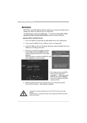
... 1. Power on the right appears. Select the proper BIOS file and press then to proceed. Press to perform the BIOS update process. 6. BIOS update completes. Motherboard Manual BIO-Flasher BIO-Flasher is built in the BIOS chip. z Shutting down or resetting the system while updating the BIOS will show the BIOS... BIOS with FAT32/16 format and single partition. The BIO-Flasher is a BIOS flashing utility providing you to download the latest BIOS file for the motherboard. 2. Select the device contains the BIOS file and press to the USB port or the floppy disk drive. 4.
... 1. Power on the right appears. Select the proper BIOS file and press then to proceed. Press to perform the BIOS update process. 6. BIOS update completes. Motherboard Manual BIO-Flasher BIO-Flasher is built in the BIOS chip. z Shutting down or resetting the system while updating the BIOS will show the BIOS... BIOS with FAT32/16 format and single partition. The BIO-Flasher is a BIOS flashing utility providing you to download the latest BIOS file for the motherboard. 2. Select the device contains the BIOS file and press to the USB port or the floppy disk drive. 4.
Setup Manual
Page 25
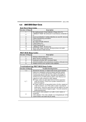
..., eliminate the possibility of interference by a malfunctioning add-in card. Consult your system manufacturer's technical support. Before declaring the motherboard beyond all expansion cards except the video adapter. If the video adapter is an add-in card, replace or 8 reseat ... be faulty. 23 This will reveal the malfunctioning card. Fatal error indicating a serious problem with known good modules. 4.4 AMI BIOS BEEP CODE G31-M4 Boot Block Beep Codes Number of Beeps Description 1 No media present. (Insert diskette in floppy drive A:) 2 "AMIBOOT.ROM" file not found...
..., eliminate the possibility of interference by a malfunctioning add-in card. Consult your system manufacturer's technical support. Before declaring the motherboard beyond all expansion cards except the video adapter. If the video adapter is an add-in card, replace or 8 reseat ... be faulty. 23 This will reveal the malfunctioning card. Fatal error indicating a serious problem with known good modules. 4.4 AMI BIOS BEEP CODE G31-M4 Boot Block Beep Codes Number of Beeps Description 1 No media present. (Insert diskette in floppy drive A:) 2 "AMIBOOT.ROM" file not found...

