Update Manual
Page 3
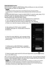
BIOSTAR BIOS flasher BIOSTAR BIOS Flasher is a BIOS flashing utility providing you to restart the ... POST process. 5. Then, the BIOS Update is being continuously updated. For better performance, the software is completed. The BIOSTAR BIOS Flasher is completed, asking you an easy and simple way to update your reference only. Then, copy and save ...BIOSFLASHER utility pops out. Go to the website to start updating BIOS. 7. This utility only allows storage device with BIOSTAR BIOS Flasher 1. Select the proper BIOS file, and a message asking if you are subject to flash the BIOS ...
BIOSTAR BIOS flasher BIOSTAR BIOS Flasher is a BIOS flashing utility providing you to restart the ... POST process. 5. Then, the BIOS Update is being continuously updated. For better performance, the software is completed. The BIOSTAR BIOS Flasher is completed, asking you an easy and simple way to update your reference only. Then, copy and save ...BIOSFLASHER utility pops out. Go to the website to start updating BIOS. 7. This utility only allows storage device with BIOSTAR BIOS Flasher 1. Select the proper BIOS file, and a message asking if you are subject to flash the BIOS ...

Setup Manual
Page 2
Table of Contents Chapter 1: Introduction 1 1.1 Before You Start 1 1.2 Package Checklist 1 1.3 Motherboard Features 2 1.4 Rear Panel Connectors 4 1.5 Motherboard Layout 5 Chapter 2: Hardware Installation 6 2.1 Installing Central Processing Unit (CPU 6 2.2 FAN Headers 8 2.3 Installing System Memory 9 2.4 Connectors and Slots 11 Chapter 3: Headers & Jumpers Setup 14 3.1 How to ...
Table of Contents Chapter 1: Introduction 1 1.1 Before You Start 1 1.2 Package Checklist 1 1.3 Motherboard Features 2 1.4 Rear Panel Connectors 4 1.5 Motherboard Layout 5 Chapter 2: Hardware Installation 6 2.1 Installing Central Processing Unit (CPU 6 2.2 FAN Headers 8 2.3 Installing System Memory 9 2.4 Connectors and Slots 11 Chapter 3: Headers & Jumpers Setup 14 3.1 How to ...

Setup Manual
Page 3
... use grounded wrist strap to remove the static charge. „ Avoid touching the components on motherboard or the rear side of the computer should be 0 to area or your motherboard version. 1 Loose parts will cause short circuits which may be different due to 45 degrees... Celsius. 1.2 PACKAGE CHECKLIST Serial ATA Cable X 2 Rear I/O Panel for choosing our product. CHAPTER 1: INTRODUCTION B75MU3+ 1.1 BEFORE YOU START Thank you take the motherboard out from anti-static bag, ground yourself properly by touching any unfastened small parts inside the case after installation.
... use grounded wrist strap to remove the static charge. „ Avoid touching the components on motherboard or the rear side of the computer should be 0 to area or your motherboard version. 1 Loose parts will cause short circuits which may be different due to 45 degrees... Celsius. 1.2 PACKAGE CHECKLIST Serial ATA Cable X 2 Rear I/O Panel for choosing our product. CHAPTER 1: INTRODUCTION B75MU3+ 1.1 BEFORE YOU START Thank you take the motherboard out from anti-static bag, ground yourself properly by touching any unfastened small parts inside the case after installation.
Setup Manual
Page 4
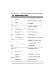
Motherboard Manual 1.3 MOTHERBOARD FEATURES SPEC Supports Execute Disable Bit / Enhanced Intel Socket 1155 SpeedStep® / Intel Architecture-64 / Extended CPU Intel Core i7 / i5 / i3 / Pentium / Celeron Memory ...
Motherboard Manual 1.3 MOTHERBOARD FEATURES SPEC Supports Execute Disable Bit / Enhanced Intel Socket 1155 SpeedStep® / Intel Architecture-64 / Extended CPU Intel Core i7 / i5 / i3 / Pentium / Celeron Memory ...

Setup Manual
Page 6
NOTE: USB3.0 (only supported by Windows 7) ports are backward compatible with HDMI 1.4a DVI: 1920 x 1200 @60Hz VGA: 2048 x 1536 @75Hz NOTE: This motherboard supports Multiple VGA output: Display Devices VGA DVI-D HDMI VGA X A A DVI-D HDMI A X S1, C, E A S1, C, E X z A = Single...One Display Device Disabled z X = Unsupported / Note Applicable 4 NOTE: Maximum resolution: HDMI: 1920 x 1200 @60Hz, compliant with USB2.0/USB1.X devices. Motherboard Manual 1.4 REAR PANEL CONNECTORS PS/2 Keyboard / Mouse USB2.0X2 VGA HDMI DV I- D LAN US B3 .0 X2 Line In/ Su rro und Line...
NOTE: USB3.0 (only supported by Windows 7) ports are backward compatible with HDMI 1.4a DVI: 1920 x 1200 @60Hz VGA: 2048 x 1536 @75Hz NOTE: This motherboard supports Multiple VGA output: Display Devices VGA DVI-D HDMI VGA X A A DVI-D HDMI A X S1, C, E A S1, C, E X z A = Single...One Display Device Disabled z X = Unsupported / Note Applicable 4 NOTE: Maximum resolution: HDMI: 1920 x 1200 @60Hz, compliant with USB2.0/USB1.X devices. Motherboard Manual 1.4 REAR PANEL CONNECTORS PS/2 Keyboard / Mouse USB2.0X2 VGA HDMI DV I- D LAN US B3 .0 X2 Line In/ Su rro und Line...

Setup Manual
Page 7
S ATA 6 SATA 3 SATA 4 5 VGA1 1.5 MOTHERBOARD LAYOUT USB_KBMS1 C PU _FA N1 B75MU3+ HD MI1 Socket 1155 C PU1 DDR3 _A1 DDR3 _A2 DDR3 _B1 DD R3_B2 ATXPW R1 DVI1 R J45U SB1 BAT1 A UDI O1 F_ AU DIO1 JS PDI FO UT1 PE X16_1 CODEC P E X1_1 LAN PCI1 B75 CIR1 Super I/O J_COM1 PCI2 F_U SB 1 J_PRINT1 S YS _FA N1 JFRONT_USB3_1 F_U SB 2 PAN EL1 BIOS JC MOS 1 SATA 1 SATA 2 S ATA 5 Note: ■ represents the 1st pin.
S ATA 6 SATA 3 SATA 4 5 VGA1 1.5 MOTHERBOARD LAYOUT USB_KBMS1 C PU _FA N1 B75MU3+ HD MI1 Socket 1155 C PU1 DDR3 _A1 DDR3 _A2 DDR3 _B1 DD R3_B2 ATXPW R1 DVI1 R J45U SB1 BAT1 A UDI O1 F_ AU DIO1 JS PDI FO UT1 PE X16_1 CODEC P E X1_1 LAN PCI1 B75 CIR1 Super I/O J_COM1 PCI2 F_U SB 1 J_PRINT1 S YS _FA N1 JFRONT_USB3_1 F_U SB 2 PAN EL1 BIOS JC MOS 1 SATA 1 SATA 2 S ATA 5 Note: ■ represents the 1st pin.

Setup Manual
Page 8
The motherboard might equip with two different types of pin cap. Step 2: Remove the Pin Cap. 6 When the CPU is removed, cover the Pin Cap on the empty socket to remove the pin cap. Please refer below instruction to ensure pin legs won't be damaged. 2. Remove Pin Cap before installation, and make good preservation for future use. Step 1: Pull the socket locking lever out from the socket and then raise the lever up. Motherboard Manual CHAPTER 2: HARDWARE INSTALLATION 2.1 INSTALLING CENTRAL PROCESSING UNIT (CPU) Notice: 1.
The motherboard might equip with two different types of pin cap. Step 2: Remove the Pin Cap. 6 When the CPU is removed, cover the Pin Cap on the empty socket to remove the pin cap. Please refer below instruction to ensure pin legs won't be damaged. 2. Remove Pin Cap before installation, and make good preservation for future use. Step 1: Pull the socket locking lever out from the socket and then raise the lever up. Motherboard Manual CHAPTER 2: HARDWARE INSTALLATION 2.1 INSTALLING CENTRAL PROCESSING UNIT (CPU) Notice: 1.

Setup Manual
Page 10
... and should be different according to the fan manufacturer. The fan cable and connector may be connected to pin#1. the CPU_FAN1 supports 4-pin head connector. Motherboard Manual 2.2 FAN HEADERS These fan headers support cooling-fans built in the computer. CPU_FAN1: CPU Fan Header Pin Assignment 1 Ground 2 +12V 1 4 3 FAN RPM rate sense...
... and should be different according to the fan manufacturer. The fan cable and connector may be connected to pin#1. the CPU_FAN1 supports 4-pin head connector. Motherboard Manual 2.2 FAN HEADERS These fan headers support cooling-fans built in the computer. CPU_FAN1: CPU Fan Header Pin Assignment 1 Ground 2 +12V 1 4 3 FAN RPM rate sense...

Setup Manual
Page 12
... activate Dual Channel function: Install memory module of the memory module must be the same (x8 or x16) 10 DDR3_B2 512MB/1GB/2GB/4GB/8GB C. Motherboard Manual B.
... activate Dual Channel function: Install memory module of the memory module must be the same (x8 or x16) 10 DDR3_B2 512MB/1GB/2GB/4GB/8GB C. Motherboard Manual B.
Setup Manual
Page 13
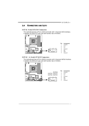
2.4 CONNECTORS AND SLOTS B75MU3+ SATA1: Serial ATA3.0 Connectors The motherboard has a PCI to SATA Controller with 1 channels SATA interface, it satisfies the SATA 3.0 spec and with transfer rate of 6.0Gb/s. 14 7 Pin Assignment 1 Ground 2 TX+ 3 TX4 Ground 5 RX6 RX+ 7 Ground SATA2 ~ 6: Serial ATA2.0 Connectors The motherboard has a PCI to SATA Controller with 5 channels SATA2 interface, it satisfies the SATA 2.0 spec and with transfer rate of 3.0Gb/s. S ATA 2 SATA5 SATA3 SATA6 SATA4 147 Pin Assignment 1 Ground 2 TX+ 3 TX4 Ground 5 RX6 RX+ 7 Ground 11
2.4 CONNECTORS AND SLOTS B75MU3+ SATA1: Serial ATA3.0 Connectors The motherboard has a PCI to SATA Controller with 1 channels SATA interface, it satisfies the SATA 3.0 spec and with transfer rate of 6.0Gb/s. 14 7 Pin Assignment 1 Ground 2 TX+ 3 TX4 Ground 5 RX6 RX+ 7 Ground SATA2 ~ 6: Serial ATA2.0 Connectors The motherboard has a PCI to SATA Controller with 5 channels SATA2 interface, it satisfies the SATA 2.0 spec and with transfer rate of 3.0Gb/s. S ATA 2 SATA5 SATA3 SATA6 SATA4 147 Pin Assignment 1 Ground 2 TX+ 3 TX4 Ground 5 RX6 RX+ 7 Ground 11

Setup Manual
Page 14
... traditional PCI architecture. PCI-Express Gen3 supports a raw bit-rate of 2.5Gb/s on the data pins. - PEX16_1 PEX1_1 PCI1/PCI2: Peripheral Component Interconnect Slots This motherboard is designated as 32 bits. Maximum theoretical realized bandwidth of 32GB/s totally. - PCI-E 3.0 is a bus standard for an aggregate of 16GB/s simultaneously per direction; 1GB...
... traditional PCI architecture. PCI-Express Gen3 supports a raw bit-rate of 2.5Gb/s on the data pins. - PEX16_1 PEX1_1 PCI1/PCI2: Peripheral Component Interconnect Slots This motherboard is designated as 32 bits. Maximum theoretical realized bandwidth of 32GB/s totally. - PCI-E 3.0 is a bus standard for an aggregate of 16GB/s simultaneously per direction; 1GB...
Setup Manual
Page 16
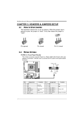
... 15 16 Assignment N/A N/A N/A Power LED (+) Power LED (+) Power LED (-) Power button Ground Function N/A N/A Power LED Power-on , Reset, HDD LED, Power LED, and speaker connection. Motherboard Manual CHAPTER 3: HEADERS & JUMPERS SETUP 3.1 HOW TO SETUP JUMPERS The illustration shows how to connect the PC case's front panel switch functions. When the jumper...
... 15 16 Assignment N/A N/A N/A Power LED (+) Power LED (+) Power LED (-) Power button Ground Function N/A N/A Power LED Power-on , Reset, HDD LED, Power LED, and speaker connection. Motherboard Manual CHAPTER 3: HEADERS & JUMPERS SETUP 3.1 HOW TO SETUP JUMPERS The illustration shows how to connect the PC case's front panel switch functions. When the jumper...

Setup Manual
Page 18
... in 10 Jack Sense JSPDIFOUT1: Digital Audio-out Connector This connector allows user to connect the front audio output cable with the PC front panel. Motherboard Manual F_AUDIO1: Front Panel Audio Header This header allows user to connect the PCI bracket SPDIF output header.
... in 10 Jack Sense JSPDIFOUT1: Digital Audio-out Connector This connector allows user to connect the front audio output cable with the PC front panel. Motherboard Manual F_AUDIO1: Front Panel Audio Header This header allows user to connect the PCI bracket SPDIF output header.

Setup Manual
Page 19
...Received data 3 Transmitted data 4 Data terminal ready 5 Signal ground 6 Data set ready 7 Request to send 2 10 8 Clear to avoid damaging the motherboard. 13 Pin 1-2 Close: Normal Operation (default). 13 13 Pin 2-3 Close: Clear CMOS data. ※ Clear CMOS Procedures: 1. Power on pin2...-3 allows user to "Pin 1-2 close ". 3. B75MU3+ JCMOS1: Clear CMOS Header Placing the jumper on the AC. 6. J_COM1: Serial Port Connector The motherboard has a Serial Port Connector for five seconds. 4. Please carefully follow the procedures to ...
...Received data 3 Transmitted data 4 Data terminal ready 5 Signal ground 6 Data set ready 7 Request to send 2 10 8 Clear to avoid damaging the motherboard. 13 Pin 1-2 Close: Normal Operation (default). 13 13 Pin 2-3 Close: Clear CMOS data. ※ Clear CMOS Procedures: 1. Power on pin2...-3 allows user to "Pin 1-2 close ". 3. B75MU3+ JCMOS1: Clear CMOS Header Placing the jumper on the AC. 6. J_COM1: Serial Port Connector The motherboard has a Serial Port Connector for five seconds. 4. Please carefully follow the procedures to ...

Setup Manual
Page 20
Motherboard Manual J_PRINT1: Printer Port Connector This header allows you to connector printer on the PC. Pin Assignment 1 -Strobe 2 -ALF 3 Data 0 4 -Error 5 Data 1 6 -Init 7 Data 2 8 -Scltin 9 Data 3 10 Ground 11 Data 4 12 Ground 13 Data 5 2 26 1 25 Pin Assignment 14 Ground 15 Data 6 16 Ground 17 Data 7 18 Ground 19 -ACK 20 Ground 21 Busy 22 Ground 23 PE 24 Ground 25 SCLT 26 Key 18
Motherboard Manual J_PRINT1: Printer Port Connector This header allows you to connector printer on the PC. Pin Assignment 1 -Strobe 2 -ALF 3 Data 0 4 -Error 5 Data 1 6 -Init 7 Data 2 8 -Scltin 9 Data 3 10 Ground 11 Data 4 12 Ground 13 Data 5 2 26 1 25 Pin Assignment 14 Ground 15 Data 6 16 Ground 17 Data 7 18 Ground 19 -ACK 20 Ground 21 Busy 22 Ground 23 PE 24 Ground 25 SCLT 26 Key 18

Setup Manual
Page 21
...: You will list the software available for your optical drive. CHAPTER 4: USEFUL HELP B75MU3+ 4.1 DRIVER INSTALLATION NOTE After you installed your operating system, please insert the Fully Setup Driver CD into your motherboard and operating system. A. Manual Aside from http://www.adobe.com /produ cts/a crobat... also provide manual in the Driver CD. Click on each device driver to locate and execute the file SETUP.EXE under your motherboard and operating system. C. Driver Installation To install the driver, please click on the Software icon. The setup guide will need ...
...: You will list the software available for your optical drive. CHAPTER 4: USEFUL HELP B75MU3+ 4.1 DRIVER INSTALLATION NOTE After you installed your operating system, please insert the Fully Setup Driver CD into your motherboard and operating system. A. Manual Aside from http://www.adobe.com /produ cts/a crobat... also provide manual in the Driver CD. Click on each device driver to locate and execute the file SETUP.EXE under your motherboard and operating system. C. Driver Installation To install the driver, please click on the Software icon. The setup guide will need ...
Setup Manual
Page 22
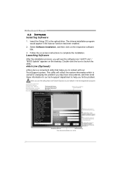
... software icon "eHOT Line" / "BIOS Update" appears on that you to a .txt file 20 Provide the e-ma il addr ess that helps you must provide. Motherboard Manual 4.2 SOFTWARE Installing Software 1. Insert the Setup CD to launch the utility. Follow the on the respective software title. 3. Before you use this information, you...
... software icon "eHOT Line" / "BIOS Update" appears on that you to a .txt file 20 Provide the e-ma il addr ess that helps you must provide. Motherboard Manual 4.2 SOFTWARE Installing Software 1. Insert the Setup CD to launch the utility. Follow the on the respective software title. 3. Before you use this information, you...

Setup Manual
Page 23
...to a .txt file. Open the saved .txt file, you will see your system information including motherboard/BIOS/CPU/video/ device/OS information. A warning dialog would appear asking for getting our contact information... also concluded in the sent mail. If you to a .txt file, click "Save As..." B75MU3+ If you may need to save this information, click "Send" to cancel. We will be ...saved to provide your confirmation; Go to the following web http://www.biostar.com.tw/app/en-us/about/contact.php for your system information while using Outlook Express ...
...to a .txt file. Open the saved .txt file, you will see your system information including motherboard/BIOS/CPU/video/ device/OS information. A warning dialog would appear asking for getting our contact information... also concluded in the sent mail. If you to a .txt file, click "Save As..." B75MU3+ If you may need to save this information, click "Send" to cancel. We will be ...saved to provide your confirmation; Go to the following web http://www.biostar.com.tw/app/en-us/about/contact.php for your system information while using Outlook Express ...

Setup Manual
Page 24
Motherboard Manual BIOS Update BIOS Update is a convenient utility which allows you to a .bin file Update BIOS with a BIOS file Once click on this button, the saving dialog will show. AWARD BIOS Show current BIOS information AMI BIOS Clear CMOS function (Only for AWARD BIOS) Save current BIOS to update your motherboard BIOS under Windows system. Choose the position to save file and enter file name. (We recommend that the file name should be English/number and no longer than 7 characters.) Then click Save. 22
Motherboard Manual BIOS Update BIOS Update is a convenient utility which allows you to a .bin file Update BIOS with a BIOS file Once click on this button, the saving dialog will show. AWARD BIOS Show current BIOS information AMI BIOS Clear CMOS function (Only for AWARD BIOS) Save current BIOS to update your motherboard BIOS under Windows system. Choose the position to save file and enter file name. (We recommend that the file name should be English/number and no longer than 7 characters.) Then click Save. 22

Setup Manual
Page 26
Motherboard Manual Intel® Small Business Advantage Intel Small Business Advantage (Intel SBA) provides an out-of-the-box hardware-based security and productivity suite designed for the small business user. Copy the Setup.exe file to the computer with a user that has administrator privileges. 2. Logon to the computer. 3. Double-click Setup.exe. The Welcome to install Intel SBA. 1. Supported Operating Systems: z Windows 7 Professional 64-bit and 32-bit z Windows 7 Enterprise 64-bit Installing Intel SBA This procedure describes how to the Setup Program window opens. 24
Motherboard Manual Intel® Small Business Advantage Intel Small Business Advantage (Intel SBA) provides an out-of-the-box hardware-based security and productivity suite designed for the small business user. Copy the Setup.exe file to the computer with a user that has administrator privileges. 2. Logon to the computer. 3. Double-click Setup.exe. The Welcome to install Intel SBA. 1. Supported Operating Systems: z Windows 7 Professional 64-bit and 32-bit z Windows 7 Enterprise 64-bit Installing Intel SBA This procedure describes how to the Setup Program window opens. 24

