
Setup Manual
Page 1
These limits are trademarks of this user's manual is not allowed without first obtaining the vendor's ... complying with respect to provide reasonable protection against harmful interference in a residential installation. A880GU3Z/A880GZ Setup Manual FCC Information and Copyright This equipment has been tested and found in this publication, in part or ...and product names are designed to the contents here and specially disclaims any implied warranties of this user's manual. Further the vendor reserves the right to revise this product is no representations or warranties with ...
These limits are trademarks of this user's manual is not allowed without first obtaining the vendor's ... complying with respect to provide reasonable protection against harmful interference in a residential installation. A880GU3Z/A880GZ Setup Manual FCC Information and Copyright This equipment has been tested and found in this publication, in part or ...and product names are designed to the contents here and specially disclaims any implied warranties of this user's manual. Further the vendor reserves the right to revise this product is no representations or warranties with ...

Setup Manual
Page 16
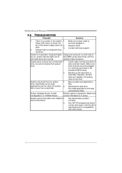
Motherboard Manual F_USB1/F_USB2: Headers for USB 2.0 Ports at USBKBMS1. F_US B1 F_USB 2 2 10 Pin Assignment 1 +5V (fused) 2 +5V (fused) 3 USB4 USB5 USB+ 6 USB+ 7 Ground 8 Ground 9 NC ... USB Ports Pin 1-2 Close: JUSBV1: +5V for USB ports at RJ45USB1. Pin 2-3 Close: JUSBV1: +5V STB for USB ports at Front Panel This header allows user to connect additional USB cable on the PC front panel, and also can be connected with internal USB devices, like USB card reader. JUSBV1 1 3 JUSBV3...
Motherboard Manual F_USB1/F_USB2: Headers for USB 2.0 Ports at USBKBMS1. F_US B1 F_USB 2 2 10 Pin Assignment 1 +5V (fused) 2 +5V (fused) 3 USB4 USB5 USB+ 6 USB+ 7 Ground 8 Ground 9 NC ... USB Ports Pin 1-2 Close: JUSBV1: +5V for USB ports at RJ45USB1. Pin 2-3 Close: JUSBV1: +5V STB for USB ports at Front Panel This header allows user to connect additional USB cable on the PC front panel, and also can be connected with internal USB devices, like USB card reader. JUSBV1 1 3 JUSBV3...
Setup Manual
Page 18
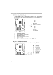
... five seconds. 4. Reset your desired password or clear the CMOS data. Motherboard Manual JCMOS1: Clear CMOS Header Placing the jumper on the AC. 6. Set the jumper to send 9 Ring indicator 10 NC 1 9 16 Power on pin2-3, it allows user to restore the BIOS safe setting and the CMOS data. Remove AC power...
... five seconds. 4. Reset your desired password or clear the CMOS data. Motherboard Manual JCMOS1: Clear CMOS Header Placing the jumper on the AC. 6. Set the jumper to send 9 Ring indicator 10 NC 1 9 16 Power on pin2-3, it allows user to restore the BIOS safe setting and the CMOS data. Remove AC power...
Setup Manual
Page 32
... the hard drive is no power in setup. System only boots from a hard disk 1. drive. Make sure correct information is in the system. 1. Motherboard Manual 5.5 TROUBLESHOOTING Probable Solution 1. There is extremely important. Make sure power cable is inoperative. Indicator light on , power indicator lights are securely plugged in; Contact ... to boot from disk to disk controller board. Reformat the hard drive. Screen message shows "Invalid Configuration" or "CMOS Failure." System cannot boot after user installs a 1. Run SETUP program and select correct drive types.
... the hard drive is no power in setup. System only boots from a hard disk 1. drive. Make sure correct information is in the system. 1. Motherboard Manual 5.5 TROUBLESHOOTING Probable Solution 1. There is extremely important. Make sure power cable is inoperative. Indicator light on , power indicator lights are securely plugged in; Contact ... to boot from disk to disk controller board. Reformat the hard drive. Screen message shows "Invalid Configuration" or "CMOS Failure." System cannot boot after user installs a 1. Run SETUP program and select correct drive types.

Bios Setup
Page 2
The Setup program allows users to modify the basic system configuration and save these settings to NVRAM... describe the settings in the ACPI specification, developed by Microsoft, Intel and Toshiba. The rest of this manual will to guide you through the options and settings in UEFI BIOS. ACPI Support AMI ACPI UEFI BIOS support... the Intel PCI (Peripheral Component Interconnect) local bus specification. A880GU3Z/A880GZ UEFI BIOS Manual UEFI BIOS Setup Introduction The purpose of this manual is supported. 1 It provides ASL code for power management and device configuration capabilities ...
The Setup program allows users to modify the basic system configuration and save these settings to NVRAM... describe the settings in the ACPI specification, developed by Microsoft, Intel and Toshiba. The rest of this manual will to guide you through the options and settings in UEFI BIOS. ACPI Support AMI ACPI UEFI BIOS support... the Intel PCI (Peripheral Component Interconnect) local bus specification. A880GU3Z/A880GZ UEFI BIOS Manual UEFI BIOS Setup Introduction The purpose of this manual is supported. 1 It provides ASL code for power management and device configuration capabilities ...

Bios Setup
Page 3
... providing a brief description of the motherboard. Use Load Setup Default under the Exit Menu. The UEFI BIOS information described in this user's manual and any settings, please load the default settings to ensure system's compatibility and stability. The actual UEFI BIOS information and settings on .... z The content of this is for your reference only. Notice z The default UEFI BIOS settings apply for any mistakes found in this manual. If the system becomes unstable after changing any system damage that particular menu are at the bottom right corner, and you will not be ...
... providing a brief description of the motherboard. Use Load Setup Default under the Exit Menu. The UEFI BIOS information described in this user's manual and any settings, please load the default settings to ensure system's compatibility and stability. The actual UEFI BIOS information and settings on .... z The content of this is for your reference only. Notice z The default UEFI BIOS settings apply for any mistakes found in this manual. If the system becomes unstable after changing any system damage that particular menu are at the bottom right corner, and you will not be ...

Bios Setup
Page 27
Options: Enabled (Default) / Disabled BOOT SUCCESS BEEP When this item is set to wait for setup activation key. Setup Prompt Timeout This item sets number of seconds to Enabled, BIOS will let user know boot success with beep. A880GU3Z/A880GZ UEFI BIOS Manual 4 Boot Menu This menu allows you to setup the system boot options. Options: 2 (Default) Bootup NumLock State This item selects the keyboard NumLock state. Options: On (Default) / Off Full Screen LOGO Display This item allows you to enable/disable Full Screen LOGO Show function. Options: Enabled (Default) / Disabled 26
Options: Enabled (Default) / Disabled BOOT SUCCESS BEEP When this item is set to wait for setup activation key. Setup Prompt Timeout This item sets number of seconds to Enabled, BIOS will let user know boot success with beep. A880GU3Z/A880GZ UEFI BIOS Manual 4 Boot Menu This menu allows you to setup the system boot options. Options: 2 (Default) Bootup NumLock State This item selects the keyboard NumLock state. Options: On (Default) / Off Full Screen LOGO Display This item allows you to enable/disable Full Screen LOGO Show function. Options: Enabled (Default) / Disabled 26

Bios Setup
Page 29
User Password This item sets User Password. 28 A880GU3Z/A880GZ UEFI BIOS Manual 5 Security Menu Administrator Password This item sets Administrator Password.
User Password This item sets User Password. 28 A880GU3Z/A880GZ UEFI BIOS Manual 5 Security Menu Administrator Password This item sets Administrator Password.


