
Setup Manual
Page 2
... 1: Introduction 1 1.1 Before You Start 1 1.2 Package Checklist 1 1.3 Motherboard Features 2 1.4 Rear Panel Connectors 3 1.5 Motherboard Layout 4 Chapter 2: Hardware Installation 5 2.1 Installing Central Processing Unit (CPU 5 2.2 FAN Headers 7 2.3 Installing System Memory 8 2.4 Connectors and Slots 10 Chapter 3: Headers & Jumpers Setup 13 3.1 How to Setup Jumpers 13 3.2 Detail Settings 13 Chapter 4: RAID Functions 18 4.1 Operating System 18 4.2 Raid...
... 1: Introduction 1 1.1 Before You Start 1 1.2 Package Checklist 1 1.3 Motherboard Features 2 1.4 Rear Panel Connectors 3 1.5 Motherboard Layout 4 Chapter 2: Hardware Installation 5 2.1 Installing Central Processing Unit (CPU 5 2.2 FAN Headers 7 2.3 Installing System Memory 8 2.4 Connectors and Slots 10 Chapter 3: Headers & Jumpers Setup 13 3.1 How to Setup Jumpers 13 3.2 Detail Settings 13 Chapter 4: RAID Functions 18 4.1 Operating System 18 4.2 Raid...

Setup Manual
Page 4
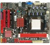
...DIMM is not Registered DIMM and ECC DIMM is not supported supported Graphics SATA 3 LAN Integrated in AMD 880G Chipset Max Shared Video Memory is 512MB DVI/HDMI/HDCP/UVD2 support Integrated Serial ATA Controller Data transfer rates up to 6 Gb/s SATA Version 3.0 specification compliant ...Realtek RTL 8111E 10 / 100 / 1000 Mb/s auto negotiation Half / Full duplex capability Integrated in AMD 880G Chipset Max Shared Video Memory is 512MB DVI/HDMI/HDCP/UVD2 support Integrated Serial ATA Controller Data transfer rates up to 6 Gb/s SATA Version 3.0 specification compliant Realtek RTL ...
...DIMM is not Registered DIMM and ECC DIMM is not supported supported Graphics SATA 3 LAN Integrated in AMD 880G Chipset Max Shared Video Memory is 512MB DVI/HDMI/HDCP/UVD2 support Integrated Serial ATA Controller Data transfer rates up to 6 Gb/s SATA Version 3.0 specification compliant ...Realtek RTL 8111E 10 / 100 / 1000 Mb/s auto negotiation Half / Full duplex capability Integrated in AMD 880G Chipset Max Shared Video Memory is 512MB DVI/HDMI/HDCP/UVD2 support Integrated Serial ATA Controller Data transfer rates up to 6 Gb/s SATA Version 3.0 specification compliant Realtek RTL ...

Setup Manual
Page 10
DDR3_A 1 DDR3_B 1 Motherboard Manual 2.3 INSTALLING SYSTEM MEMORY A. Insert the DIMM vertically and firmly into the slot until the retaining chip snap back in place and the DIMM is properly seated. 8 Unlock a DIMM slot by pressing the retaining clips outward. Align a DIMM on the slot such that the notch on the DIMM matches the break on the Slot. 2. Memory Modules 1.
DDR3_A 1 DDR3_B 1 Motherboard Manual 2.3 INSTALLING SYSTEM MEMORY A. Insert the DIMM vertically and firmly into the slot until the retaining chip snap back in place and the DIMM is properly seated. 8 Unlock a DIMM slot by pressing the retaining clips outward. Align a DIMM on the slot such that the notch on the DIMM matches the break on the Slot. 2. Memory Modules 1.

Setup Manual
Page 11
C. B. Dual Channel Memory installation Please refer to the following requirements to activate Dual Channel function: Install memory module of the same density in pairs, shown in the table Dual Channel Status DDR3_A1 DDR3_B1 Disabled X O Disabled O X Enabled O O (O means memory installed, X means memory not installed.) The DRAM bus width of the memory module must be the same (x8 or x16) 9 Memory Capacity DIMM Socket Location DDR3 Module DDR3_A1 512MB/1GB/2GB/4GB DDR3_B1 512MB/1GB/2GB/4GB A880GU3Z/A880GZ Total Memory Size Max is 8GB.
C. B. Dual Channel Memory installation Please refer to the following requirements to activate Dual Channel function: Install memory module of the same density in pairs, shown in the table Dual Channel Status DDR3_A1 DDR3_B1 Disabled X O Disabled O X Enabled O O (O means memory installed, X means memory not installed.) The DRAM bus width of the memory module must be the same (x8 or x16) 9 Memory Capacity DIMM Socket Location DDR3 Module DDR3_A1 512MB/1GB/2GB/4GB DDR3_B1 512MB/1GB/2GB/4GB A880GU3Z/A880GZ Total Memory Size Max is 8GB.

Setup Manual
Page 31
... eliminate the possibility of interference by a malfunctioning add-in flash device) POST BIOS Beep Codes Number of Beeps Description 1 Memory refresh timer error 3 Base memory read/write test error 6 Keyboard controller BAT command failed 7 General exception error (processor exception interrupt error) 8 Display... memory error (system video adapter) Troubleshooting POST BIOS Beep Codes Number of the add-in card, replace or 8 reseat the video...
... eliminate the possibility of interference by a malfunctioning add-in flash device) POST BIOS Beep Codes Number of Beeps Description 1 Memory refresh timer error 3 Base memory read/write test error 6 Keyboard controller BAT command failed 7 General exception error (processor exception interrupt error) 8 Display... memory error (system video adapter) Troubleshooting POST BIOS Beep Codes Number of the add-in card, replace or 8 reseat the video...
Bios Setup
Page 4
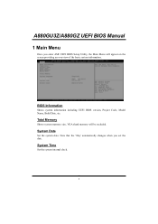
System Date Set the system date. Note that the 'Day' automatically changes when you enter AMI UEFI BIOS Setup Utility, the Main Menu will be excluded. Total Memory Shows system memory size, VGA shard memory will appear on the screen providing an overview of the basic system information. BIOS Information Shows system information including UEFI BIOS version, Project Code, Model Name, Build Date, etc. System Time Set the system internal clock. 3 A880GU3Z/A880GZ UEFI BIOS Manual 1 Main Menu Once you set the date.
System Date Set the system date. Note that the 'Day' automatically changes when you enter AMI UEFI BIOS Setup Utility, the Main Menu will be excluded. Total Memory Shows system memory size, VGA shard memory will appear on the screen providing an overview of the basic system information. BIOS Information Shows system information including UEFI BIOS version, Project Code, Model Name, Build Date, etc. System Time Set the system internal clock. 3 A880GU3Z/A880GZ UEFI BIOS Manual 1 Main Menu Once you set the date.

Bios Setup
Page 20
... item allows you to control the Surround View Function. Options: 560 (Default) / Min: 150, Max: 1200 Surround View This item allows you to select the memory mode used for internal graphics. Options: Enabled (Default) / Disabled 19 Options: Disabled (Default) / Enabled GFX Engine Clock This item allows you to set the FB...
... item allows you to control the Surround View Function. Options: 560 (Default) / Min: 150, Max: 1200 Surround View This item allows you to select the memory mode used for internal graphics. Options: Enabled (Default) / Disabled 19 Options: Disabled (Default) / Enabled GFX Engine Clock This item allows you to set the FB...

Bios Setup
Page 30
... This item allows you to select CPU NB Voltage Control. CPUNB Over Voltage This item allows you to select Memory Voltage Control. CPU Over Voltage This item allows you to select Chipset Voltage Control. 29 A880GU3Z/A880GZ UEFI BIOS Manual 6 Performance Menu This submenu allows ...
... This item allows you to select CPU NB Voltage Control. CPUNB Over Voltage This item allows you to select Memory Voltage Control. CPU Over Voltage This item allows you to select Chipset Voltage Control. 29 A880GU3Z/A880GZ UEFI BIOS Manual 6 Performance Menu This submenu allows ...

Bios Setup
Page 34
... to select the DRAM Frequency programming method. A880GU3Z/A880GZ UEFI BIOS Manual DRAM Timing Configuration MCT Timing Mode This item allows you to set the Memory Clock. If Limit, the DRAM speed will be programmed regardless of SPD. If Auto, the DRAM speed will not exceed the specified value.
... to select the DRAM Frequency programming method. A880GU3Z/A880GZ UEFI BIOS Manual DRAM Timing Configuration MCT Timing Mode This item allows you to set the Memory Clock. If Limit, the DRAM speed will be programmed regardless of SPD. If Auto, the DRAM speed will not exceed the specified value.

Bios Setup
Page 36
... Interleaving is an advanced chipset technique used to enable or disable the remapping of memory. Options: Auto (Default) / Disabled Memory Hole Remapping This item allows you to more than one piece of the overlapped PCI memory above the total physical memory. Options: Disable Link (Default) / Enabled 35 Options: Auto (Default) / Disabled Channel Interleaving This...
... Interleaving is an advanced chipset technique used to enable or disable the remapping of memory. Options: Auto (Default) / Disabled Memory Hole Remapping This item allows you to more than one piece of the overlapped PCI memory above the total physical memory. Options: Disable Link (Default) / Enabled 35 Options: Auto (Default) / Disabled Channel Interleaving This...


