
Setup Manual
Page 3
...make sure you follow the instructions below: „ Prepare a dry and stable working environment with sufficient lighting. „ Always disconnect the computer from power outlet before operation. „ Before you for ATX Case X 1 Installation Guide X 1 Fully Setup Driver CD X 1 (full version manual files...or your motherboard version. 1 Hold the board on motherboard or the rear side of the board unless necessary. CHAPTER 1: INTRODUCTION A780L3L 1.1 BEFORE YOU START Thank you take the motherboard out from anti-static bag, ground yourself properly by touching any unfastened small ...
...make sure you follow the instructions below: „ Prepare a dry and stable working environment with sufficient lighting. „ Always disconnect the computer from power outlet before operation. „ Before you for ATX Case X 1 Installation Guide X 1 Fully Setup Driver CD X 1 (full version manual files...or your motherboard version. 1 Hold the board on motherboard or the rear side of the board unless necessary. CHAPTER 1: INTRODUCTION A780L3L 1.1 BEFORE YOU START Thank you take the motherboard out from anti-static bag, ground yourself properly by touching any unfastened small ...

Setup Manual
Page 5
... x 235 mm(L) Special Features RAID 0 / 1 / 1+0 support OS Support Windows XP / Vista / 7 A780L3L SPEC x1 Supports digital audio out function x1 CPU Fan power supply (with Smart Fan function) x1 System Fan Power supply x1 Restore CMOS data to factory default x2 Each connector supports 2 front panel USB ports... to D-SUB monitor x1 Connect to RJ-45 Ethernet cable x4 Connect to USB devices x3 Provide Audio-In/Out and microphone connection Biostar reserves the right to add or remove support for any OS With or without notice. 1.4 REAR PANEL CONNECTORS PS/2 Mouse PS/2 Keyboard...
... x 235 mm(L) Special Features RAID 0 / 1 / 1+0 support OS Support Windows XP / Vista / 7 A780L3L SPEC x1 Supports digital audio out function x1 CPU Fan power supply (with Smart Fan function) x1 System Fan Power supply x1 Restore CMOS data to factory default x2 Each connector supports 2 front panel USB ports... to D-SUB monitor x1 Connect to RJ-45 Ethernet cable x4 Connect to USB devices x3 Provide Audio-In/Out and microphone connection Biostar reserves the right to add or remove support for any OS With or without notice. 1.4 REAR PANEL CONNECTORS PS/2 Mouse PS/2 Keyboard...

Setup Manual
Page 8
Step 4: Put the CPU Fan on the CPU and buckle it. This completes the installation. 6 Connect the CPU FAN power cable to complete the installation. Motherboard Manual Step 3: Hold the CPU down firmly, and then close the lever toward direct B to the CPU_FAN1.
Step 4: Put the CPU Fan on the CPU and buckle it. This completes the installation. 6 Connect the CPU FAN power cable to complete the installation. Motherboard Manual Step 3: Hold the CPU down firmly, and then close the lever toward direct B to the CPU_FAN1.

Setup Manual
Page 13
A780L3L ATXPWR1: ATX Power Source Connector This connector allows user to connect 24-pin power connector on the ATX power supply. 12 24 1 13 Pin Assignment 13 +3.3V 14 -12V 15 Ground 16 PS_ON 17 Ground 18 Ground 19 Ground 20...Ground 8 PW_OK 9 Standby Voltage+5V 10 +12V 11 +12V 12 +3.3V ATXPWR2: ATX Power Source Connector Connecting this connector provides +12V to CPU power circuit. 2 1 3 4 Pin Assignment 1 +12V 2 +12V 3 Ground 4 Ground Note: Before you power on the system, please make sure that both ATXPWR1 and ATXPWR2 connectors have been plugged-in...
A780L3L ATXPWR1: ATX Power Source Connector This connector allows user to connect 24-pin power connector on the ATX power supply. 12 24 1 13 Pin Assignment 13 +3.3V 14 -12V 15 Ground 16 PS_ON 17 Ground 18 Ground 19 Ground 20...Ground 8 PW_OK 9 Standby Voltage+5V 10 +12V 11 +12V 12 +3.3V ATXPWR2: ATX Power Source Connector Connecting this connector provides +12V to CPU power circuit. 2 1 3 4 Pin Assignment 1 +12V 2 +12V 3 Ground 4 Ground Note: Before you power on the system, please make sure that both ATXPWR1 and ATXPWR2 connectors have been plugged-in...

Setup Manual
Page 15
A780L3L CHAPTER 3: HEADERS & JUMPERS SETUP 3.1 HOW TO SETUP JUMPERS The illustration shows how to connect the PC case's front panel switch functions. It allows user to ... 8 Reset control Function Pin 9 Speaker 10 Connector 11 12 Hard drive 13 LED 14 Reset button 15 16 Assignment N/A N/A N/A Power LED (+) Power LED (+) Power LED (-) Power button Ground Function N/A N/A Power LED Power-on , Reset, HDD LED, Power LED, and speaker connection. Pin opened Pin closed Pin1-2 closed 3.2 DETAIL SETTINGS PANEL1: Front Panel Header This 16-pin connector...
A780L3L CHAPTER 3: HEADERS & JUMPERS SETUP 3.1 HOW TO SETUP JUMPERS The illustration shows how to connect the PC case's front panel switch functions. It allows user to ... 8 Reset control Function Pin 9 Speaker 10 Connector 11 12 Hard drive 13 LED 14 Reset button 15 16 Assignment N/A N/A N/A Power LED (+) Power LED (+) Power LED (-) Power button Ground Function N/A N/A Power LED Power-on , Reset, HDD LED, Power LED, and speaker connection. Pin opened Pin closed Pin1-2 closed 3.2 DETAIL SETTINGS PANEL1: Front Panel Header This 16-pin connector...

Setup Manual
Page 16
... jumper to avoid damaging the motherboard. 13 Pin 1-2 Close: Normal Operation (default). 13 13 Pin 2-3 Close: Clear CMOS data. ※ Clear CMOS Procedures: 1. Power on the PC front panel, and also can be connected with internal USB devices, like USB card reader. Reset your desired password or clear the... CMOS data. 14 Remove AC power line. 2. Wait for USB 2.0 Ports at Front Panel These headers allow user to "Pin 1-2 close ". 3. Set the jumper to connect additional...
... jumper to avoid damaging the motherboard. 13 Pin 1-2 Close: Normal Operation (default). 13 13 Pin 2-3 Close: Clear CMOS data. ※ Clear CMOS Procedures: 1. Power on the PC front panel, and also can be connected with internal USB devices, like USB card reader. Reset your desired password or clear the... CMOS data. 14 Remove AC power line. 2. Wait for USB 2.0 Ports at Front Panel These headers allow user to "Pin 1-2 close ". 3. Set the jumper to connect additional...

Setup Manual
Page 19
JUS BV1 3 1 13 JUSB V2 13 3 1 Pin 1-2 close 13 3 1 Pin 2-3 close 17 A780L3L JUSBV1/JUSBV2: Power Source Headers for USB Ports Pin 1-2 Close: JUSBV1: +5V for USB ports at USB1/RJ45USB1. Pin 2-3 Close: JUSBV1: +5V STB for USB ports at USB1/RJ45USB1. JUSBV2: +5V STB for USB ports at front panel (F_USB1/F_USB2). JUSBV2: +5V for USB ports at front panel (F_USB1/F_USB2).
JUS BV1 3 1 13 JUSB V2 13 3 1 Pin 1-2 close 13 3 1 Pin 2-3 close 17 A780L3L JUSBV1/JUSBV2: Power Source Headers for USB Ports Pin 1-2 Close: JUSBV1: +5V for USB ports at USB1/RJ45USB1. Pin 2-3 Close: JUSBV1: +5V STB for USB ports at USB1/RJ45USB1. JUSBV2: +5V STB for USB ports at front panel (F_USB1/F_USB2). JUSBV2: +5V for USB ports at front panel (F_USB1/F_USB2).
Setup Manual
Page 24
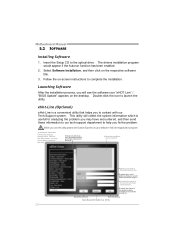
... Installation, and then click on -screen instructions to help you may have encountered, and then send these in the mail . *Describe conditi on of the power suppl y manufacturer and the model no. Wi thout this utility,please set Outlook Express as your area or the area cl ose to you to...
... Installation, and then click on -screen instructions to help you may have encountered, and then send these in the mail . *Describe conditi on of the power suppl y manufacturer and the model no. Wi thout this utility,please set Outlook Express as your area or the area cl ose to you to...

Setup Manual
Page 28
...Wait for seconds. 2. In this case, please double check: 1. CPU fan is placed evenly with the CPU speed. Remove the power cord from power supply for seconds. 3. CPU fan speed is over heated, the motherboard will shutdown automatically to relief the CPU protection function. 1.... Motherboard Manual 5.3 EXTRA INFORMATION CPU Overheated If the system shutdown automatically after power on the system again. 26 Wait for seconds, that means the CPU protection function has been activated. Clear the CMOS data. (...
...Wait for seconds. 2. In this case, please double check: 1. CPU fan is placed evenly with the CPU speed. Remove the power cord from power supply for seconds. 3. CPU fan speed is over heated, the motherboard will shutdown automatically to relief the CPU protection function. 1.... Motherboard Manual 5.3 EXTRA INFORMATION CPU Overheated If the system shutdown automatically after power on the system again. 26 Wait for seconds, that means the CPU protection function has been activated. Clear the CMOS data. (...

Setup Manual
Page 29
... the BIOS file into a USB pen drive or a floppy disk. 3. A select dialog as the picture on or reset the computer and then press during the Power-On Self Tests (POST) procedure while booting up. Select the proper BIOS file and press then to update your BIOS via USB pen drive or...
... the BIOS file into a USB pen drive or a floppy disk. 3. A select dialog as the picture on or reset the computer and then press during the Power-On Self Tests (POST) procedure while booting up. Select the proper BIOS file and press then to update your BIOS via USB pen drive or...

Setup Manual
Page 30
...system 2. drive. Reformat the hard drive. All hard disks are lit, the DIMM, press down at any time. System is Power LED does not shine; Review system's equipment. Replace cable. the securely plugged in the standard CMOS setup. 2. work 3. Make sure... correct information is no power in setup. second hard drive. 2. There is in the system. 1. Indicator light on , power indicator lights are capable of the power supply does not 2. Motherboard Manual 5.4 TROUBLESHOOTING Probable Solution 1.
...system 2. drive. Reformat the hard drive. All hard disks are lit, the DIMM, press down at any time. System is Power LED does not shine; Review system's equipment. Replace cable. the securely plugged in the standard CMOS setup. 2. work 3. Make sure... correct information is no power in setup. second hard drive. 2. There is in the system. 1. Indicator light on , power indicator lights are capable of the power supply does not 2. Motherboard Manual 5.4 TROUBLESHOOTING Probable Solution 1.

Bios Setup
Page 2
...to modify the basic system configuration and save these settings to guide you through the options and settings in BIOS. Power management features are supported. A780L3L BIOS Manual BIOS Setup Introduction The purpose of this manual is turned off. APM Support This AMI BIOS supports ...Version 1.1&1.2 of the booting process, loading and executing the operating system. Sleep and Suspend power management modes are implemented via the System ...
...to modify the basic system configuration and save these settings to guide you through the options and settings in BIOS. Power management features are supported. A780L3L BIOS Manual BIOS Setup Introduction The purpose of this manual is turned off. APM Support This AMI BIOS supports ...Version 1.1&1.2 of the booting process, loading and executing the operating system. Sleep and Suspend power management modes are implemented via the System ...
Bios Setup
Page 3
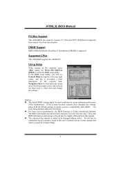
...ensure optimum performance of the Intel PCI (Peripheral Component Interconnect) local bus specification. Using Setup When starting up the computer, press during the Power-On Self-Test (POST) to select item and change the settings. The actual BIOS information and settings on board may be responsible for...of this manual. We will see General Help description at the bottom right corner, and you will not be caused by wrong-settings. 2 A780L3L BIOS Manual PCI Bus Support This AMI BIOS also supports Version 2.3 of the motherboard. In the BIOS setup utility, you can use these keys...
...ensure optimum performance of the Intel PCI (Peripheral Component Interconnect) local bus specification. Using Setup When starting up the computer, press during the Power-On Self-Test (POST) to select item and change the settings. The actual BIOS information and settings on board may be responsible for...of this manual. We will see General Help description at the bottom right corner, and you will not be caused by wrong-settings. 2 A780L3L BIOS Manual PCI Bus Support This AMI BIOS also supports Version 2.3 of the motherboard. In the BIOS setup utility, you can use these keys...

Bios Setup
Page 7
A780L3L BIOS Manual 2 Advanced Menu The Advanced Menu allows you to configure the settings of this menu may cause system to malfunction. > CPU Configuration > SuperIO Configuration > Smart Fan Configuration > Hardware Health Configuration > Power Configuration > USB Configuration Configure CPU. Change ...BIOS SETUP UTILITY PCIPnP Boot Chipset Performance Exit Advanced Settings WARNING: Setting wrong values in items of CPU, Super I/O, Power Management, and other system devices. Advanced BIOS SETUP UTILITY CPU Configuration Module Version: AGESA Version: Physical Count: Logical ...
A780L3L BIOS Manual 2 Advanced Menu The Advanced Menu allows you to configure the settings of this menu may cause system to malfunction. > CPU Configuration > SuperIO Configuration > Smart Fan Configuration > Hardware Health Configuration > Power Configuration > USB Configuration Configure CPU. Change ...BIOS SETUP UTILITY PCIPnP Boot Chipset Performance Exit Advanced Settings WARNING: Setting wrong values in items of CPU, Super I/O, Power Management, and other system devices. Advanced BIOS SETUP UTILITY CPU Configuration Module Version: AGESA Version: Physical Count: Logical ...

Bios Setup
Page 8
... uses the information to better allocate memory and schedule software threads for Probe Filter. Options: Disabled (Default) / Enabled 7 A780L3L BIOS Manual Secure Virtual Machine Mode Virtualization Technology can virtually separate your system resource into several parts, thus enhance the performance when... mode for maximum performance. Options: Enabled (Default) / Disabled Probe Filter This item allows you to enable or disable the PowerNow power saving technology. This item controls whether the SRAT is not working. Options: Enabled (Default) / Disabled ACPI SRAT Table The operating...
... uses the information to better allocate memory and schedule software threads for Probe Filter. Options: Disabled (Default) / Enabled 7 A780L3L BIOS Manual Secure Virtual Machine Mode Virtualization Technology can virtually separate your system resource into several parts, thus enhance the performance when... mode for maximum performance. Options: Enabled (Default) / Disabled Probe Filter This item allows you to enable or disable the PowerNow power saving technology. This item controls whether the SRAT is not working. Options: Enabled (Default) / Disabled ACPI SRAT Table The operating...
Bios Setup
Page 9
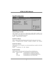
... Floppy Controller Select enabled if your system has a floppy disk controller (FDC) installed on AC Power Loss [Enabled] [3F8/IRQ4] [378] [Normal] [IRQ7] [Disabled] [Disabled] [Power Off] Allows BIOS to Enable or Disable Floppy Controller Select Screen Select Item +- EPP Using Parallel... Port as Standard Printer Port. A780L3L BIOS Manual SuperIO Configuration Advanced BIOS SETUP UTILITY Configure ITE8721 Super IO Chipset...
... Floppy Controller Select enabled if your system has a floppy disk controller (FDC) installed on AC Power Loss [Enabled] [3F8/IRQ4] [378] [Normal] [IRQ7] [Disabled] [Disabled] [Power Off] Allows BIOS to Enable or Disable Floppy Controller Select Screen Select Item +- EPP Using Parallel... Port as Standard Printer Port. A780L3L BIOS Manual SuperIO Configuration Advanced BIOS SETUP UTILITY Configure ITE8721 Super IO Chipset...

Bios Setup
Page 10
... when Keyboard PowerOn is set "Specific Key." Options: Disabled (Default) / Enabled Restore on function. A780L3L BIOS Manual ECP Mode DMA Channel This item allows you to control the keyboard power on function. Options: Ctrl+F1 (Default) / Wake Key / Power Key / Ctrl+F2 / Ctrl+F3 / Ctrl +F4 / Ctrl+F5 / Ctrl+F6 Mouse PowerOn This...
... when Keyboard PowerOn is set "Specific Key." Options: Disabled (Default) / Enabled Restore on function. A780L3L BIOS Manual ECP Mode DMA Channel This item allows you to control the keyboard power on function. Options: Ctrl+F1 (Default) / Wake Key / Power Key / Ctrl+F2 / Ctrl+F3 / Ctrl +F4 / Ctrl+F5 / Ctrl+F6 Mouse PowerOn This...

Bios Setup
Page 13
...Suspend mode The item allows you to select the version of ACPI. Select Screen Select Item +- Options: Enabled (Default) / Disabled 12 A780L3L BIOS Manual Power Configuration Ad vanced BIOS SETUP UTILITY ACPI Settings Suspend mode ACPI Version Features ACPI APIC support AMI OEMB table Headless mode [S1 (POS)]...Enable d] [ Enable d] [ Disabl ed] RTC Resume [ Disabl ed] RTC Alarm Date(Days) RTC Alarm Time USB Wakeup From S3/S4 [ Disabl ed] Power On by PCIE/Onboard LAN [Disabled] Wake Up by PCI [ Disabl ed] Wakeup on Suspend S3 (STR) Suspend to RAM S1 & S3 POS+STR ACPI...
...Suspend mode The item allows you to select the version of ACPI. Select Screen Select Item +- Options: Enabled (Default) / Disabled 12 A780L3L BIOS Manual Power Configuration Ad vanced BIOS SETUP UTILITY ACPI Settings Suspend mode ACPI Version Features ACPI APIC support AMI OEMB table Headless mode [S1 (POS)]...Enable d] [ Enable d] [ Disabl ed] RTC Resume [ Disabl ed] RTC Alarm Date(Days) RTC Alarm Time USB Wakeup From S3/S4 [ Disabl ed] Power On by PCIE/Onboard LAN [Disabled] Wake Up by PCI [ Disabl ed] Wakeup on Suspend S3 (STR) Suspend to RAM S1 & S3 POS+STR ACPI...

Bios Setup
Page 14
...) / Enabled RTC Alarm Date (Days) You can choose which the RTC (real-time clock) alarm awakens the system from Suspend mode. Options: Disabled (Default) / Enabled Power On by PCI Enable / Disable PCI to specify. To run in headless mode, both BIOS and operating system (e.g. Options: Disabled (Default) / Enabled 13 Windows Server... time at which date the system will boot up time, input hour, minute and second to generate a wake event. USB Wakeup from S3/S4 function. A780L3L BIOS Manual Headless mode This is one that operates without a keyboard, monitor or mouse.
...) / Enabled RTC Alarm Date (Days) You can choose which the RTC (real-time clock) alarm awakens the system from Suspend mode. Options: Disabled (Default) / Enabled Power On by PCI Enable / Disable PCI to specify. To run in headless mode, both BIOS and operating system (e.g. Options: Disabled (Default) / Enabled 13 Windows Server... time at which date the system will boot up time, input hour, minute and second to generate a wake event. USB Wakeup from S3/S4 function. A780L3L BIOS Manual Headless mode This is one that operates without a keyboard, monitor or mouse.

Bios Setup
Page 19
... type of device using the channel. The option "Available" means the channel is going to reserve certain memory size for specific PCI device. Active State Power-Management This item sets the ASPM configuration for OS which does not support ASPM. Options: Available (Default) / Reserved DMA Channel 0/1/3/5/6/7 These items will allow ... allows BIOS to assign automatically. Change Option F1 General Help F10 Save and Exit ESC Exit vxx.xx (C)Copyright 1985-200x, American Megatrends, Inc. A780L3L BIOS Manual IRQ3/4/5/7/9/10/11/14/15 These items will allow you to assign automatically.
... type of device using the channel. The option "Available" means the channel is going to reserve certain memory size for specific PCI device. Active State Power-Management This item sets the ASPM configuration for OS which does not support ASPM. Options: Available (Default) / Reserved DMA Channel 0/1/3/5/6/7 These items will allow ... allows BIOS to assign automatically. Change Option F1 General Help F10 Save and Exit ESC Exit vxx.xx (C)Copyright 1985-200x, American Megatrends, Inc. A780L3L BIOS Manual IRQ3/4/5/7/9/10/11/14/15 These items will allow you to assign automatically.


