Setup Manual
Page 13
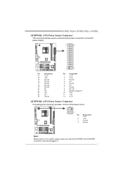
A780L M2G+/A780L M2L+/A780L ATXPWR1: ATX Power Source Connector This connector allows user to connect 24-pin power connector on the ATX power supply. 12 24 1 13 Pin Assignment 13 +3.3V 14 -12V 15 Ground 16 PS_ON 17 Ground 18 Ground 19 Ground 20 NC 21 +5V 22 +5V 23 +5V 24 Ground Pin...+5V 10 +12V 11 +12V 12 +3.3V ATXPWR2: ATX Power Source Connector Connecting this connector provides +12V to CPU power circuit. 2 1 3 4 Pin Assignment 1 +12V 2 +12V 3 Ground 4 Ground Note: Before power on the system, please make sure that both ATXPWR1 and ATXPWR2...
A780L M2G+/A780L M2L+/A780L ATXPWR1: ATX Power Source Connector This connector allows user to connect 24-pin power connector on the ATX power supply. 12 24 1 13 Pin Assignment 13 +3.3V 14 -12V 15 Ground 16 PS_ON 17 Ground 18 Ground 19 Ground 20 NC 21 +5V 22 +5V 23 +5V 24 Ground Pin...+5V 10 +12V 11 +12V 12 +3.3V ATXPWR2: ATX Power Source Connector Connecting this connector provides +12V to CPU power circuit. 2 1 3 4 Pin Assignment 1 +12V 2 +12V 3 Ground 4 Ground Note: Before power on the system, please make sure that both ATXPWR1 and ATXPWR2...

Setup Manual
Page 15
... the jumper is placed on button 13 When the jumper cap is "open". Pin opened Pin closed Pin1-2 closed 3.2 DETAIL SETTINGS PANEL1: Front Panel Header This 16-pin connector includes Power-on, Reset, HDD LED, Power LED, and speaker connection. A780L M2G+/A780L M2L+/A780L CHAPTER 3: HEADERS & JUMPERS SETUP 3.1 HOW TO SETUP JUMPERS The illustration shows how to...
... the jumper is placed on button 13 When the jumper cap is "open". Pin opened Pin closed Pin1-2 closed 3.2 DETAIL SETTINGS PANEL1: Front Panel Header This 16-pin connector includes Power-on, Reset, HDD LED, Power LED, and speaker connection. A780L M2G+/A780L M2L+/A780L CHAPTER 3: HEADERS & JUMPERS SETUP 3.1 HOW TO SETUP JUMPERS The illustration shows how to...
Setup Manual
Page 16
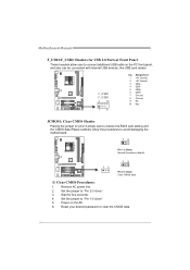
...for USB 2.0 Ports at Front Panel These headers allow user to "Pin 2-3 close ". 5. Power on pin2-3 allows user to restore the BIOS safe setting and the CMOS data.lPease carefully follow the procedures to "Pin 1-2 close ". 3. Reset your desired password or clear the CMOS...JCMOS1: Clear CMOS Header Placing the jumper on the AC. 6. Remove AC power line. 2. Motherboard Manual F_USB1/F_USB2: Headers for five seconds. 4. Set the jumper to avoid damaging the motherboard. 13 Pin 1-2 Close: Normal Operation (default). 13 13 Pin 2-3 Close: Clear CMOS data. ※ Clear CMOS Procedures: 1.
...for USB 2.0 Ports at Front Panel These headers allow user to "Pin 2-3 close ". 5. Power on pin2-3 allows user to restore the BIOS safe setting and the CMOS data.lPease carefully follow the procedures to "Pin 1-2 close ". 3. Reset your desired password or clear the CMOS...JCMOS1: Clear CMOS Header Placing the jumper on the AC. 6. Remove AC power line. 2. Motherboard Manual F_USB1/F_USB2: Headers for five seconds. 4. Set the jumper to avoid damaging the motherboard. 13 Pin 1-2 Close: Normal Operation (default). 13 13 Pin 2-3 Close: Clear CMOS data. ※ Clear CMOS Procedures: 1.

Setup Manual
Page 19
JUSBV1 3 1 13 JUSBV2 13 3 1 Pin 1-2 close 13 3 1 Pin 2-3 close 17 JUSBV2: +5V for USB ports at front panel (F_USB1/F_USB2). JUSBV2: +5V STB for USB ports at front panel (F_USB1/F_USB2). Pin 2-3 Close: JUSBV1: +5V STB for USB ports at USB1/RJ45USB1. A780L M2G+/A780L M2L+/A780L JUSBV1/JUSBV2: Power Source Headers for USB Ports Pin 1-2 Close: JUSBV1: +5V for USB ports at USB1/RJ45USB1.
JUSBV1 3 1 13 JUSBV2 13 3 1 Pin 1-2 close 13 3 1 Pin 2-3 close 17 JUSBV2: +5V for USB ports at front panel (F_USB1/F_USB2). JUSBV2: +5V STB for USB ports at front panel (F_USB1/F_USB2). Pin 2-3 Close: JUSBV1: +5V STB for USB ports at USB1/RJ45USB1. A780L M2G+/A780L M2L+/A780L JUSBV1/JUSBV2: Power Source Headers for USB Ports Pin 1-2 Close: JUSBV1: +5V for USB ports at USB1/RJ45USB1.


