Update Manual
Page 3
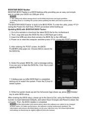
... with FAT32/16 format and single partition. 2. Choose [fs0] to be slightly different from this manual. The information and pictures described above about the software are subject to search for the motherboard. 2. BIOSTAR BIOS flasher BIOSTAR BIOS Flasher is completed. Insert the USB pen drive that contains the BIOS file to flash the... utility providing you are for your BIOS via USB pen drive. 1. Then, copy and save the BIOS file into a USB flash (pen) drive. 3. The BIOSTAR BIOS Flasher is built in the BIOS ROM. All the information and content above are sure to the USB port. 4.
... with FAT32/16 format and single partition. 2. Choose [fs0] to be slightly different from this manual. The information and pictures described above about the software are subject to search for the motherboard. 2. BIOSTAR BIOS flasher BIOSTAR BIOS Flasher is completed. Insert the USB pen drive that contains the BIOS file to flash the... utility providing you are for your BIOS via USB pen drive. 1. Then, copy and save the BIOS file into a USB flash (pen) drive. 3. The BIOSTAR BIOS Flasher is built in the BIOS ROM. All the information and content above are sure to the USB port. 4.
Setup Manual
Page 3
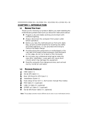
... motherboard, please make sure you follow the instructions below: „ Prepare a dry and stable working environment with sufficient lighting. „ Always disconnect the computer from power outlet before operation. „ Before you for ATX Case X 1 Installation Guide X 1 Fully Setup Driver CD X 1 (full version manual... unless necessary. A780G M2+ SE/A780V M2+ SE/A760G M2+/A740G M2+ SE CHAPTER 1: INTRODUCTION 1.1 BEFORE YOU START Thank you take the motherboard out from dangerous area, such as heat source, humid air and water. 1.2 PACKAGE CHECKLIST HDD Cable X 1 Serial ATA Cable X 1 Rear...
... motherboard, please make sure you follow the instructions below: „ Prepare a dry and stable working environment with sufficient lighting. „ Always disconnect the computer from power outlet before operation. „ Before you for ATX Case X 1 Installation Guide X 1 Fully Setup Driver CD X 1 (full version manual... unless necessary. A780G M2+ SE/A780V M2+ SE/A760G M2+/A740G M2+ SE CHAPTER 1: INTRODUCTION 1.1 BEFORE YOU START Thank you take the motherboard out from dangerous area, such as heat source, humid air and water. 1.2 PACKAGE CHECKLIST HDD Cable X 1 Serial ATA Cable X 1 Rear...
Setup Manual
Page 4
... bit AMD 64 Architecture enables 32 and 64 bit computing computing Supports Hyper Transport 3.0 and PowerNow Supports Hyper Transport 2.0 and PowerNow Athlon Max. Power:125W; Motherboard Manual 1.3 MOTHERBOARD FEATURES CPU FSB Chipset Super I /O functionality functionality Low Pin Count Interface Low Pin Count Interface Environment Control initiatives Environment Control initiatives H/W Monitor H/W Monitor ITE's "Smart...
... bit AMD 64 Architecture enables 32 and 64 bit computing computing Supports Hyper Transport 3.0 and PowerNow Supports Hyper Transport 2.0 and PowerNow Athlon Max. Power:125W; Motherboard Manual 1.3 MOTHERBOARD FEATURES CPU FSB Chipset Super I /O functionality functionality Low Pin Count Interface Low Pin Count Interface Environment Control initiatives Environment Control initiatives H/W Monitor H/W Monitor ITE's "Smart...
Setup Manual
Page 8
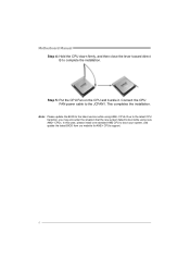
... to the JCFAN1. Connect the CPU FAN power cable to boot your system, and update the latest BIOS from our website for AM2+ CPUs support. 6 Motherboard Manual Step 4: Hold the CPU down firmly, and then close the lever toward direct B to the latest version while using new AM2+ CPUs. Step 5: Put the...
... to the JCFAN1. Connect the CPU FAN power cable to boot your system, and update the latest BIOS from our website for AM2+ CPUs support. 6 Motherboard Manual Step 4: Hold the CPU down firmly, and then close the lever toward direct B to the latest version while using new AM2+ CPUs. Step 5: Put the...
Setup Manual
Page 10
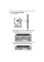
Insert the DIMM vertically and firmly into the slot until the retaining chip snap back in place and the DIMM is properly seated. 8 Unlock a DIMM slot by pressing the retaining clips outward. DIMMA1 DIMMB1 Motherboard Manual 2.3 INSTALLING SYSTEM MEMORY A. Align a DIMM on the slot such that the notch on the DIMM matches the break on the Slot. 2. Memory Modules 1.
Insert the DIMM vertically and firmly into the slot until the retaining chip snap back in place and the DIMM is properly seated. 8 Unlock a DIMM slot by pressing the retaining clips outward. DIMMA1 DIMMB1 Motherboard Manual 2.3 INSTALLING SYSTEM MEMORY A. Align a DIMM on the slot such that the notch on the DIMM matches the break on the Slot. 2. Memory Modules 1.
Setup Manual
Page 12
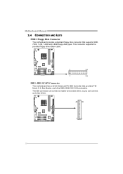
This connector supports the provided floppy drive ribbon cable. 2 34 1 33 IDE1: IDE/ATAPI Connector The motherboard has a 32-bit Enhanced PCI IDE Controller that supports 360K, 720K, 1.2M, 1.44M and 2.88M floppy disk types. Motherboard Manual 2.4 CONNECTORS AND SLOTS FDD1: Floppy Disk Connector The motherboard provides a standard floppy disk connector that provides PIO Mode 0~4, Bus Master, and Ultra DMA 33/66/100/133 functionality. The IDE connector can connect a master and a slave drive, so you can connect up to two drives. 40 39 21 10
This connector supports the provided floppy drive ribbon cable. 2 34 1 33 IDE1: IDE/ATAPI Connector The motherboard has a 32-bit Enhanced PCI IDE Controller that supports 360K, 720K, 1.2M, 1.44M and 2.88M floppy disk types. Motherboard Manual 2.4 CONNECTORS AND SLOTS FDD1: Floppy Disk Connector The motherboard provides a standard floppy disk connector that provides PIO Mode 0~4, Bus Master, and Ultra DMA 33/66/100/133 functionality. The IDE connector can connect a master and a slave drive, so you can connect up to two drives. 40 39 21 10
Setup Manual
Page 14
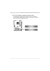
Motherboard Manual PCI1~PCI2: Peripheral Component Interconnect Slots This motherboard is designated as 32 bits. This PCI slot is equipped with 2 standard PCI slots. PCI1 PCI2 12 PCI stands for Peripheral Component Interconnect, and it is a bus standard for expansion cards.
Motherboard Manual PCI1~PCI2: Peripheral Component Interconnect Slots This motherboard is designated as 32 bits. This PCI slot is equipped with 2 standard PCI slots. PCI1 PCI2 12 PCI stands for Peripheral Component Interconnect, and it is a bus standard for expansion cards.
Setup Manual
Page 16
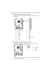
Motherboard Manual JATXPWR1: ATX Power Source Connector This connector allows user to connect 24-pin power connector on the ATX power supply. 12 24 Pin Assignment 13 +3....
Motherboard Manual JATXPWR1: ATX Power Source Connector This connector allows user to connect 24-pin power connector on the ATX power supply. 12 24 Pin Assignment 13 +3....
Setup Manual
Page 18
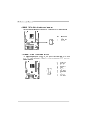
This header allows only HD audio front panel connector; AC'97 connector is not acceptable. 10 9 2 1 Pin Assignment 1 Mic Left in 2 Ground 3 Mic Right in 4 GPIO 5 Right line in 6 Jack Sense 7 Front Sense 8 Key 9 Left line in 10 Jack Sense 16 Motherboard Manual JSPDIF_OUT1: Digital Audio-out Connector This connector allows user to connect the front audio output cable with the PC front panel. Pin Assignment 1 +5V 2 SPDIF_OUT 1 3 Ground 3 JAUDIOF1: Front Panel Audio Header This header allows user to connect the PCI bracket SPDIF output header.
This header allows only HD audio front panel connector; AC'97 connector is not acceptable. 10 9 2 1 Pin Assignment 1 Mic Left in 2 Ground 3 Mic Right in 4 GPIO 5 Right line in 6 Jack Sense 7 Front Sense 8 Key 9 Left line in 10 Jack Sense 16 Motherboard Manual JSPDIF_OUT1: Digital Audio-out Connector This connector allows user to connect the front audio output cable with the PC front panel. Pin Assignment 1 +5V 2 SPDIF_OUT 1 3 Ground 3 JAUDIOF1: Front Panel Audio Header This header allows user to connect the PCI bracket SPDIF output header.
Setup Manual
Page 20
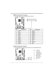
... 17 Data 7 18 Ground 19 -ACK 20 Ground 21 Busy 22 Ground 23 PE 24 Ground 25 SCLT 26 Key JCOM1: Serial port Connector The motherboard has a Serial Port Connector for connecting RS-232 Port. Motherboard Manual JPRNT1: Printer Port Connector This header allows you to send 9 Ring indicator 10 NC 1 9 18
... 17 Data 7 18 Ground 19 -ACK 20 Ground 21 Busy 22 Ground 23 PE 24 Ground 25 SCLT 26 Key JCOM1: Serial port Connector The motherboard has a Serial Port Connector for connecting RS-232 Port. Motherboard Manual JPRNT1: Printer Port Connector This header allows you to send 9 Ring indicator 10 NC 1 9 18
Setup Manual
Page 22
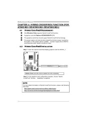
.... 4.2 HYBRID CROSSFIREX INSTALLATION Step 1: Insert the Hybrid CrossFireX-Ready graphics card into slot completely. Step 2: In the graphics card configuration program, choose "Hybrid CrossFireX" function. Motherboard Manual CHAPTER 4: HYBRID CROSSFIREX FUNCTION (FOR A780G M2+ SE/A780V M2+ SE/A760G M2+) 4.1 HYBRID CROSSFIREX REQUIREMENTS Only Windows Vista supports Hybrid CrossFireX function. A power supply...
.... 4.2 HYBRID CROSSFIREX INSTALLATION Step 1: Insert the Hybrid CrossFireX-Ready graphics card into slot completely. Step 2: In the graphics card configuration program, choose "Hybrid CrossFireX" function. Motherboard Manual CHAPTER 4: HYBRID CROSSFIREX FUNCTION (FOR A780G M2+ SE/A780V M2+ SE/A760G M2+) 4.1 HYBRID CROSSFIREX REQUIREMENTS Only Windows Vista supports Hybrid CrossFireX function. A power supply...
Setup Manual
Page 24
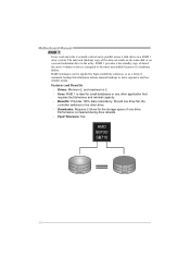
.... - Benefits: Provides 100% data redundancy. Should one drive. Performance is actually carried out in parallel across 2 disk drives in the array. Motherboard Manual RAID 1: Every read and write is impaired during drive rebuilds. - Fault Tolerance: Yes. Block 1 Block 2 Block 3 Block 1 Block 2... Block 3 22 Drawbacks: Requires 2 drives for small databases or any other application that eliminates tedious manual backups to the other drive. - The mirrored (backup) copy of the data can be applied for high-availability solutions, or as a ...
.... - Benefits: Provides 100% data redundancy. Should one drive. Performance is actually carried out in parallel across 2 disk drives in the array. Motherboard Manual RAID 1: Every read and write is impaired during drive rebuilds. - Fault Tolerance: Yes. Block 1 Block 2 Block 3 Block 1 Block 2... Block 3 22 Drawbacks: Requires 2 drives for small databases or any other application that eliminates tedious manual backups to the other drive. - The mirrored (backup) copy of the data can be applied for high-availability solutions, or as a ...
Setup Manual
Page 26
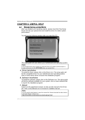
... the file SETUP.EXE under your optical drive and install the driver for your motherboard and operating system. C. Please download the latest version of Acrobat Reader software from the paperback manual, we also provide manual in the Driver CD. B. Motherboard Manual CHAPTER 6: USEFUL HELP 6.1 DRIVER INSTALLATION NOTE After you installed your operating system, please insert...
... the file SETUP.EXE under your optical drive and install the driver for your motherboard and operating system. C. Please download the latest version of Acrobat Reader software from the paperback manual, we also provide manual in the Driver CD. B. Motherboard Manual CHAPTER 6: USEFUL HELP 6.1 DRIVER INSTALLATION NOTE After you installed your operating system, please insert...
Setup Manual
Page 28
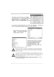
Motherboard Manual After filling up this information to a .txt file, click "Save As..." A warning dialog would appear asking for getting our contact information. 26 Enter the file ... system information while using Outlook Express as your default e-mail client application, you to the following web http://www.biostar.com.tw/app/en-us/about/contact.php for your system information including motherboard/BIOS/CPU/video/ device/OS information. Open the saved .txt file, you want to save the system information...
Motherboard Manual After filling up this information to a .txt file, click "Save As..." A warning dialog would appear asking for getting our contact information. 26 Enter the file ... system information while using Outlook Express as your default e-mail client application, you to the following web http://www.biostar.com.tw/app/en-us/about/contact.php for your system information including motherboard/BIOS/CPU/video/ device/OS information. Open the saved .txt file, you want to save the system information...
Setup Manual
Page 30
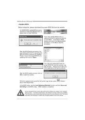
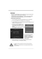
... be slightly different from the website. Please choose the proper BIOS file for requesting the BIOS file which is going to be changed without notice. Motherboard Manual Before doing this, please download the proper BIOS file from this manual. 28 The actual information and settings on OK to be updated.
... be slightly different from the website. Please choose the proper BIOS file for requesting the BIOS file which is going to be changed without notice. Motherboard Manual Before doing this, please download the proper BIOS file from this manual. 28 The actual information and settings on OK to be updated.
Setup Manual
Page 32
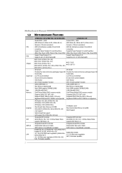
... the POST process. Insert the USB pen drive or the floppy disk that contains the BIOS file to download the latest BIOS file for the motherboard. 2. Go to the website to the USB port or the floppy disk drive. 4. Press to enter the utility. 5. Select the device contains ...updating the BIOS will lead to perform the BIOS update process. 6. Then, save the BIOS file into a USB pen drive or a floppy disk. 3. Motherboard Manual BIO-Flasher BIO-Flasher is built in the BIOS chip. After the update process, the utility will show the BIOS files and their respective information...
... the POST process. Insert the USB pen drive or the floppy disk that contains the BIOS file to download the latest BIOS file for the motherboard. 2. Go to the website to the USB port or the floppy disk drive. 4. Press to enter the utility. 5. Select the device contains ...updating the BIOS will lead to perform the BIOS update process. 6. Then, save the BIOS file into a USB pen drive or a floppy disk. 3. Motherboard Manual BIO-Flasher BIO-Flasher is built in the BIOS chip. After the update process, the utility will show the BIOS files and their respective information...
Setup Manual
Page 34
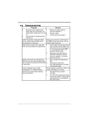
... securely plugged in the standard CMOS setup. 2. Replace cable. All hard disks are capable of the DIMM, press down at all 1. Reformat the hard drive. Motherboard Manual 6.5 TROUBLESHOOTING Probable Solution 1. inside power supply does not turn on . 3. Contact technical support. 2. Keyboard lights are on both ends are lit, and hard drive is...
... securely plugged in the standard CMOS setup. 2. Replace cable. All hard disks are capable of the DIMM, press down at all 1. Reformat the hard drive. Motherboard Manual 6.5 TROUBLESHOOTING Probable Solution 1. inside power supply does not turn on . 3. Contact technical support. 2. Keyboard lights are on both ends are lit, and hard drive is...
Bios Manual
Page 2
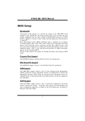
...0A specification. BIOS activates at the first stag e o f the booting process, loading and executing the operating system. T he rest of this manual will to guide you through the options and settings in the ACPI specification, developed by Microso ft, Intel and T oshiba. 1 Basic Input-Output...figuration capabilities as virus and password prot ection or chipset fine-tuning options are also included in the AMI BIOS Setup program on this motherboard. EPA Green PC Support T his AMI BIOS supports Version 1.1&1.2 of the Advanced Power Management (APM) speci fication. APM Support T ...
...0A specification. BIOS activates at the first stag e o f the booting process, loading and executing the operating system. T he rest of this manual will to guide you through the options and settings in the ACPI specification, developed by Microso ft, Intel and T oshiba. 1 Basic Input-Output...figuration capabilities as virus and password prot ection or chipset fine-tuning options are also included in the AMI BIOS Setup program on this motherboard. EPA Green PC Support T his AMI BIOS supports Version 1.1&1.2 of the Advanced Power Management (APM) speci fication. APM Support T ...
Bios Manual
Page 3
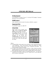
...any mistakes found in this manual is providing a brief description of the Intel PCI (Peripheral Component Interconn ect) local bus speci fication. The actual BIOS information and settings on board may be chang ed without notice. T he content of the motherboard. We will see General Help... description at the bottom right corner, and you will not be slightly different from this is for that particular menu are at the top right corner, and this manual. z T he BIOS information described ...
...any mistakes found in this manual is providing a brief description of the Intel PCI (Peripheral Component Interconn ect) local bus speci fication. The actual BIOS information and settings on board may be chang ed without notice. T he content of the motherboard. We will see General Help... description at the bottom right corner, and you will not be slightly different from this is for that particular menu are at the top right corner, and this manual. z T he BIOS information described ...
Bios Manual
Page 13
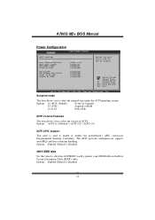
... v1.0 (Default) / ACPI v2.0 / ACPI v3.0 ACPI APIC support T his item is used for Syst em Suspend. Options: Enabled (Default) / Disabled 12 A760G M2+ BIOS Manual Power Configuration Advanced BIOS S ETUP UTILITY ACPI Settings Suspe nd mode ACPI Version Featu res ACPI APIC support AMI O EMB table Headl ess mode RTC... Resum e On RING [ S1 (POS)] [ ACPI v1.0] [ Enabled] [ Enabled] [ Disabled] [ Disabled] [ Disabled] [ Disabled] [ Disabled] Sele ct the ACPI stat e used to enable or disable the motherboard's APIC (Advan ced Programmable Interrupt Controller).
... v1.0 (Default) / ACPI v2.0 / ACPI v3.0 ACPI APIC support T his item is used for Syst em Suspend. Options: Enabled (Default) / Disabled 12 A760G M2+ BIOS Manual Power Configuration Advanced BIOS S ETUP UTILITY ACPI Settings Suspe nd mode ACPI Version Featu res ACPI APIC support AMI O EMB table Headl ess mode RTC... Resum e On RING [ S1 (POS)] [ ACPI v1.0] [ Enabled] [ Enabled] [ Disabled] [ Disabled] [ Disabled] [ Disabled] [ Disabled] Sele ct the ACPI stat e used to enable or disable the motherboard's APIC (Advan ced Programmable Interrupt Controller).


