

RS232 Commands for PDP and IFP Products
Page 2
... or receive the RS232 protocol command. 2 Description 2.1 Hardware specification LCD communication port in the rear side (1) Connector type: DSUB 9 Pin Male (2) Pin Assignment Pin # Signal Remark Male DSUB 9Pin 1 NC 2 RXD Input to LCD Monitor 3 TXD Output from LCD Monitor 4 NC (outside view) 5 GND 6 NC 7 NC 8 NC 9 NC frame GND *Use of RS232 interface communication between Commercial Display and PC or other control unit with PC 2.2 Communication Setting -
... or receive the RS232 protocol command. 2 Description 2.1 Hardware specification LCD communication port in the rear side (1) Connector type: DSUB 9 Pin Male (2) Pin Assignment Pin # Signal Remark Male DSUB 9Pin 1 NC 2 RXD Input to LCD Monitor 3 TXD Output from LCD Monitor 4 NC (outside view) 5 GND 6 NC 7 NC 8 NC 9 NC frame GND *Use of RS232 interface communication between Commercial Display and PC or other control unit with PC 2.2 Communication Setting -
RS232 Commands for PDP and IFP Products
Page 7
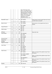
...691; 002: HDMI or HDMI1 ʳ 003: HDMI2 ʳ 004: DisplayPort ʳ 005: SDI ʳ 006: Multi-Media 89 000: Internal All the buttons at both keypad board and remote controller have no function. ʳ All the buttons at the keypad...have this feature. ʳ Option, not support if the platform doesn't have this feature. ʳ Option, not support if the platform doesn't have this feature. Button&IR Control Button Control Image Retention OSD Info Box All Reset Picture Mode Chroma (Color) Phase (Tint) Backlight Adaptive Contrast Color Temp Audio Source Speaker ʳʳ ʳ 8ʳ ...
...691; 002: HDMI or HDMI1 ʳ 003: HDMI2 ʳ 004: DisplayPort ʳ 005: SDI ʳ 006: Multi-Media 89 000: Internal All the buttons at both keypad board and remote controller have no function. ʳ All the buttons at the keypad...have this feature. ʳ Option, not support if the platform doesn't have this feature. ʳ Option, not support if the platform doesn't have this feature. Button&IR Control Button Control Image Retention OSD Info Box All Reset Picture Mode Chroma (Color) Phase (Tint) Backlight Adaptive Contrast Color Temp Audio Source Speaker ʳʳ ʳ 8ʳ ...

User Manual - PH460 & PL460
Page 3
... the display 7 BenQ ecoFACTS 8 Package contents 10 Optional accessories 10 Setting up the display 11 Mounting the display 11 Parts of the display and their functions 13 Rear panel 13 Input/output terminals 15 Remote control 17 Using the remote control 18 Connection 19 Connecting audio/video signals 19 Connecting power 25 Basic operations 26 Turning the display on or off 26 Locking/unlocking the controls 26 Switching input signals 26 Adjusting audio volume level 26 Network connection 27 Connecting to a LAN 27 Controlling the display 27 The OSD (On-Screen Display) menu 28...
... the display 7 BenQ ecoFACTS 8 Package contents 10 Optional accessories 10 Setting up the display 11 Mounting the display 11 Parts of the display and their functions 13 Rear panel 13 Input/output terminals 15 Remote control 17 Using the remote control 18 Connection 19 Connecting audio/video signals 19 Connecting power 25 Basic operations 26 Turning the display on or off 26 Locking/unlocking the controls 26 Switching input signals 26 Adjusting audio volume level 26 Network connection 27 Connecting to a LAN 27 Controlling the display 27 The OSD (On-Screen Display) menu 28...

User Manual - PH460 & PL460
Page 5
... the AC mains, disconnect the power cord plug from the AC receptacle. • Do not place this display properly may be of sufficient magnitude to constitute a risk of electric shock to the presence of important operating and maintenance (servicing) instructions in the literature accompanying the appliance. Refer servicing to ensure the best working condition. • Use only the accessories approved or...
... the AC mains, disconnect the power cord plug from the AC receptacle. • Do not place this display properly may be of sufficient magnitude to constitute a risk of electric shock to the presence of important operating and maintenance (servicing) instructions in the literature accompanying the appliance. Refer servicing to ensure the best working condition. • Use only the accessories approved or...

User Manual - PH460 & PL460
Page 6
... ' or 'image retention' which is also liable to 'screen burn-in red, blue or green) or unlit. When a cart is required when the apparatus has been damaged in direct sun or where direct sun or spot lighting will shine onto the LCD panel, as power-supply cord or plug is not a defect. • LCD screens, like plasma (PDP) and conventional CRT (Cathode...
... ' or 'image retention' which is also liable to 'screen burn-in red, blue or green) or unlit. When a cart is required when the apparatus has been damaged in direct sun or where direct sun or spot lighting will shine onto the LCD panel, as power-supply cord or plug is not a defect. • LCD screens, like plasma (PDP) and conventional CRT (Cathode...

User Manual - PH460 & PL460
Page 13
Lights up green when the power is activated. • Indicates the operating status of the display and their functions Rear panel 1 23 4 56 No. Screen Display (OSD) menu. 3 MENU Opens or closes the OSD menu. 4 5 Power button • Scrolls through settings and options in Power Save High mode. - Name Description 1 • Receives command signals from the remote control. Turns the display on . - Remote control sensor / Ambient light sensor / Power indicator • Detects ambient lighting conditions around the display and adjusts screen brightness automatically ...
Lights up green when the power is activated. • Indicates the operating status of the display and their functions Rear panel 1 23 4 56 No. Screen Display (OSD) menu. 3 MENU Opens or closes the OSD menu. 4 5 Power button • Scrolls through settings and options in Power Save High mode. - Name Description 1 • Receives command signals from the remote control. Turns the display on . - Remote control sensor / Ambient light sensor / Power indicator • Detects ambient lighting conditions around the display and adjusts screen brightness automatically ...

User Manual - PH460 & PL460
Page 19
... with the audio/video ports on the remote control. Always grasp and pull the connectors at the end of the cable. • Ensure that incorrect connections may adversely affect picture quality. • Do not remove cables from this input, press the VGA button on the display and the devices you connect cables: • Please turn off all cables are fully inserted and firmly seated. Connect the computer's audio output jack...
... with the audio/video ports on the remote control. Always grasp and pull the connectors at the end of the cable. • Ensure that incorrect connections may adversely affect picture quality. • Do not remove cables from this input, press the VGA button on the display and the devices you connect cables: • Please turn off all cables are fully inserted and firmly seated. Connect the computer's audio output jack...

User Manual - PH460 & PL460
Page 20
If needed, connect the computer's audio output jack to the AUDIO IN (AUDIO1) jack on the display using a suitable audio cable. 3. To view video image from this input, press the DVI or DP/HDMI-1/HDMI-2 button on a computer using a DVI-D cable. If the computer has a DisplayPort/HDMI output jack, connect the computer's DisplayPort/HDMI output jack to the DISPLAY PORT/HDMI-1/ HDMI-2 input jack on the display using a DisplayPort/HDMI cable or a DVI-D to the DVI-D output jack on the remote control. RS-232C-OUT...
If needed, connect the computer's audio output jack to the AUDIO IN (AUDIO1) jack on the display using a suitable audio cable. 3. To view video image from this input, press the DVI or DP/HDMI-1/HDMI-2 button on a computer using a DVI-D cable. If the computer has a DisplayPort/HDMI output jack, connect the computer's DisplayPort/HDMI output jack to the DISPLAY PORT/HDMI-1/ HDMI-2 input jack on the display using a DisplayPort/HDMI cable or a DVI-D to the DVI-D output jack on the remote control. RS-232C-OUT...

User Manual - PH460 & PL460
Page 27
... password to the previous menu, highlight Execute and press ENTER on the remote control. Make sure the Setting > Control Setting menu is set to LAN if you would like to the corresponding ports on the display and your display and the display is on or in standby mode, you can be displayed. Enter the IP address of the display in the address bar of the display. Connect a RJ45 cable to turn...
... password to the previous menu, highlight Execute and press ENTER on the remote control. Make sure the Setting > Control Setting menu is set to LAN if you would like to the corresponding ports on the display and your display and the display is on or in standby mode, you can be displayed. Enter the IP address of the display in the address bar of the display. Connect a RJ45 cable to turn...

User Manual - PH460 & PL460
Page 31
...the audio output source from SPEAKERS (R/L) on the rear connector panel. Audio Source Sets the audio input source. Standard: Flat settings. Balance Adjusts the audio balance. Speaker Sets the audio source. Line-Out: Selects the audio output source from the speakers. Reset DisplayPort HDMI1 HDMI2 Resets all settings in the Sound menu. Bass Adjusts the audio bass. External: Selects the audio output source from the internal speakers. Audio1 Audio2 Sound menu Sound Sound Mode Treble Bass Balance Surround Speaker Audio Source Reset The OSD (On-Screen Display) menu 31...
...the audio output source from SPEAKERS (R/L) on the rear connector panel. Audio Source Sets the audio input source. Standard: Flat settings. Balance Adjusts the audio balance. Speaker Sets the audio source. Line-Out: Selects the audio output source from the speakers. Reset DisplayPort HDMI1 HDMI2 Resets all settings in the Sound menu. Bass Adjusts the audio bass. External: Selects the audio output source from the internal speakers. Audio1 Audio2 Sound menu Sound Sound Mode Treble Bass Balance Surround Speaker Audio Source Reset The OSD (On-Screen Display) menu 31...

User Manual - PH460 & PL460
Page 32
32 The OSD (On-Screen Display) menu Screen menu Screen PAP Setting Display Wall Aspect Full Adjust Screen Freeze Off Name PAP Setting (Picture and Picture) :Move ENTER :Enter EXIT :Exit Description • PAP: Turns on or off . • Power On Delay: Choose to enable or disable a sequence in Picture) and PBP (Picture by Picture) functions. • Active Picture: For the PIP, selects the main or sub picture to operate. See Supported PAP input signal combination on page...
32 The OSD (On-Screen Display) menu Screen menu Screen PAP Setting Display Wall Aspect Full Adjust Screen Freeze Off Name PAP Setting (Picture and Picture) :Move ENTER :Enter EXIT :Exit Description • PAP: Turns on or off . • Power On Delay: Choose to enable or disable a sequence in Picture) and PBP (Picture by Picture) functions. • Active Picture: For the PIP, selects the main or sub picture to operate. See Supported PAP input signal combination on page...

User Manual - PH460 & PL460
Page 37
... connection diagram. Point the remote control to the first display which IR OUT port connects to the second display's IR IN port, and the second display's IR OUT port connects to show the current input source and resolution onscreen. See Connecting multiple displays on or off . • RGB Signal: Sets the type of signal for a piece of video equipment or PC connected to the HDMI of your display. • Date • Model Name • Serial Number • Operating Time • Software...
... connection diagram. Point the remote control to the first display which IR OUT port connects to the second display's IR IN port, and the second display's IR OUT port connects to show the current input source and resolution onscreen. See Connecting multiple displays on or off . • RGB Signal: Sets the type of signal for a piece of video equipment or PC connected to the HDMI of your display. • Date • Model Name • Serial Number • Operating Time • Software...
User Manual - PH460 & PL460
Page 44
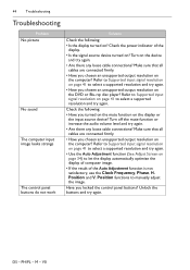
... all cables are connected firmly. • Have you locked the control panel buttons? Refer to Supported input signal resolution on page 41 to let the display automatically optimize the display of computer image. • If the result of the display. • Is the signal source device turned on? DS - Have you chosen an unsupported output resolution on the computer? 44 Troubleshooting Troubleshooting Problem No picture No sound The computer input image looks strange The control panel buttons...
... all cables are connected firmly. • Have you locked the control panel buttons? Refer to Supported input signal resolution on page 41 to let the display automatically optimize the display of computer image. • If the result of the display. • Is the signal source device turned on? DS - Have you chosen an unsupported output resolution on the computer? 44 Troubleshooting Troubleshooting Problem No picture No sound The computer input image looks strange The control panel buttons...
Color Management Manual
Page 4
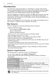
...; Supported calibration targets: - Gamma (1.8/2.0/2.2/2.4) - It works by first measuring and comparing the color characteristics of each display easily on a host computer, or backup and restore calibration data quickly. 4 Introduction Introduction The uniformity in image representation is a vital element in creating a video wall that meets the following minimum hardware and software requirements: CPU Pentium 1GHz Free memory 1 GB Hard disk space 400 MB Operating...
...; Supported calibration targets: - Gamma (1.8/2.0/2.2/2.4) - It works by first measuring and comparing the color characteristics of each display easily on a host computer, or backup and restore calibration data quickly. 4 Introduction Introduction The uniformity in image representation is a vital element in creating a video wall that meets the following minimum hardware and software requirements: CPU Pentium 1GHz Free memory 1 GB Hard disk space 400 MB Operating...

Color Management Manual
Page 5
... in a perfectly linear display (doubling the signal level doubles the light output). Calibration overview 5 Calibration overview Calibration workflow The diagram below lists the basic workflow for performing calibration using the Color Management for all displays. One of the common methods of the video input signal to choose a different gamma target for the first time. Step 1: Install Color Management on a host PC (see page 7) Step 2: Connect the color meter to the PC...
... in a perfectly linear display (doubling the signal level doubles the light output). Calibration overview 5 Calibration overview Calibration workflow The diagram below lists the basic workflow for performing calibration using the Color Management for all displays. One of the common methods of the video input signal to choose a different gamma target for the first time. Step 1: Install Color Management on a host PC (see page 7) Step 2: Connect the color meter to the PC...

Color Management Manual
Page 7
From the Start menu, select Control Panel > User Accounts and Family Safety > User Account. 2. Click on -screen instructions to complete the installation. Preparations 7 Preparations The following operations must be performed before you can use the Color Management to calibrate your display(s). To disable UAC: 1. Click OK and restart the computer to transmit control signals. Connecting the color meter Follow the instructions provided in Windows 7, the User Access Control (UAC) must be temporarily disabled. Follow...
From the Start menu, select Control Panel > User Accounts and Family Safety > User Account. 2. Click on -screen instructions to complete the installation. Preparations 7 Preparations The following operations must be performed before you can use the Color Management to calibrate your display(s). To disable UAC: 1. Click OK and restart the computer to transmit control signals. Connecting the color meter Follow the instructions provided in Windows 7, the User Access Control (UAC) must be temporarily disabled. Follow...

Color Management Manual
Page 17
.... Settings menu Option/Setting Connection Color meter Center pattern Description Selects a COM port that is used for color meter installation. Overview of components and functions 17 Restore Loads (restores) the LUT values and backlight settings of a display from a backup file. (*.lut file) Click to the display(s). To select a COM port: 1. Click Connect to establish RS-232C connection to select a display (display box) on the screen for RS-232C connection. To select a center pattern...
.... Settings menu Option/Setting Connection Color meter Center pattern Description Selects a COM port that is used for color meter installation. Overview of components and functions 17 Restore Loads (restores) the LUT values and backlight settings of a display from a backup file. (*.lut file) Click to the display(s). To select a COM port: 1. Click Connect to establish RS-232C connection to select a display (display box) on the screen for RS-232C connection. To select a center pattern...
Color Management Manual
Page 21
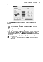
... the Adjust box. 3. Click Set. Manual Adjust tool Overview of components and functions 21 The Manual Adjust tool allows you to reset all color settings by clicking the Set default button before clicking Set. • For the adjustments you performed using the Manual Adjust tool to take effect, you want to apply color settings without performing measurement, check the Without measurement checkbox before performing a new calibration. If you need to restart the display. •...
... the Adjust box. 3. Click Set. Manual Adjust tool Overview of components and functions 21 The Manual Adjust tool allows you to reset all color settings by clicking the Set default button before clicking Set. • For the adjustments you performed using the Manual Adjust tool to take effect, you want to apply color settings without performing measurement, check the Without measurement checkbox before performing a new calibration. If you need to restart the display. •...
Color Management Manual
Page 23
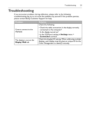
...; Is the COM port setting in Settings menu > Connection correct? Is the display correctly connected to the computer? • Is the display turned on the Display Wall tab Solution Check the following troubleshooting tips to try to solve the problems by yourself. Check the display's ID setting. When calibrating multiple displays, each display must be given an unique ID for help. Troubleshooting 23 Troubleshooting If you encounter problems during calibration, please refer to...
...; Is the COM port setting in Settings menu > Connection correct? Is the display correctly connected to the computer? • Is the display turned on the Display Wall tab Solution Check the following troubleshooting tips to try to solve the problems by yourself. Check the display's ID setting. When calibrating multiple displays, each display must be given an unique ID for help. Troubleshooting 23 Troubleshooting If you encounter problems during calibration, please refer to...
PH460 Data Sheet
Page 1
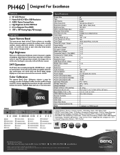
...PH460 Specifications Screen Size Type Light Source Active Area (mm) Resolution (pixels) Brightness (typ.) Native Contrast Ratio (typ.) Response Time (GTG) Pixel Pitch (H x W) Frame Rate Viewing Angle (H / V) Color Gamut (x% NTSC) Color Depth Power (AC) Input / Output Power Switch VGA Input / Output DVI Input / Output HDMI Input / Output Composite Video In / Out (BNC) Component In (YPbPr, RCA) S-Video In / Out DisplayPort Input USB Player (Photo, Video) RS232 Input / Output OPS Slot RJ45 Port Audio W (Amp) Internal Speaker Power Supply Power Consumption (Max) Power Consumption (Standby) Power...
...PH460 Specifications Screen Size Type Light Source Active Area (mm) Resolution (pixels) Brightness (typ.) Native Contrast Ratio (typ.) Response Time (GTG) Pixel Pitch (H x W) Frame Rate Viewing Angle (H / V) Color Gamut (x% NTSC) Color Depth Power (AC) Input / Output Power Switch VGA Input / Output DVI Input / Output HDMI Input / Output Composite Video In / Out (BNC) Component In (YPbPr, RCA) S-Video In / Out DisplayPort Input USB Player (Photo, Video) RS232 Input / Output OPS Slot RJ45 Port Audio W (Amp) Internal Speaker Power Supply Power Consumption (Max) Power Consumption (Standby) Power...


