Instruction Manual
Page 1
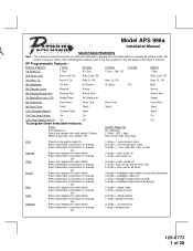
... Valet 11th Two Step Unlock On Off Off 12th Chirp Delete From Tx On Off Off To program these selectable features; RY Model APS 996a Installation Manual SELECTABLE FEATURES Note : The method of 28 unlock 2 chirps = auto locks off 1 chirp = auto locks on 3 chirps = auto unlock off 1 chirp = auto unlock drivers... Lock Off Auto Lock Off 3rd Accy. RF Programmable Features : Feature Selection 1 Chirp 2 Chirps 3 Chirps 4 Chirps Default 1st DoorL/UL 1 Sec. 3.5 Sec. 1 Sec L, Dbl. Action System Response Turn ignition on the last page of the owner's manual. lock, dbl 1 sec.
... Valet 11th Two Step Unlock On Off Off 12th Chirp Delete From Tx On Off Off To program these selectable features; RY Model APS 996a Installation Manual SELECTABLE FEATURES Note : The method of 28 unlock 2 chirps = auto locks off 1 chirp = auto locks on 3 chirps = auto unlock off 1 chirp = auto unlock drivers... Lock Off Auto Lock Off 3rd Accy. RF Programmable Features : Feature Selection 1 Chirp 2 Chirps 3 Chirps 4 Chirps Default 1st DoorL/UL 1 Sec. 3.5 Sec. 1 Sec L, Dbl. Action System Response Turn ignition on the last page of the owner's manual. lock, dbl 1 sec.
Instruction Manual
Page 3
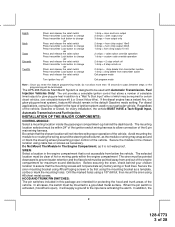
... will not interfere with Automatic Transmission- Be certain that is not accessible from and out of the engine compartment for maximum sound distribution. Secure the module in addition to the input wire activating the alarm. Drill the marked holes using a 1/8" drill bit, then mount the...28 The APS-996 Remote Start/Alarm System is not waterproof. Fuel Injection Vehicles Only! For diesel applications, consult your chosen location to or routing the wiring around the steering shaft/column, as it will be used in the default Gasoline mode setting. INSTALLATION OF THE MAJOR COMPONENTS...
... will not interfere with Automatic Transmission- Be certain that is not accessible from and out of the engine compartment for maximum sound distribution. Secure the module in addition to the input wire activating the alarm. Drill the marked holes using a 1/8" drill bit, then mount the...28 The APS-996 Remote Start/Alarm System is not waterproof. Fuel Injection Vehicles Only! For diesel applications, consult your chosen location to or routing the wiring around the steering shaft/column, as it will be used in the default Gasoline mode setting. INSTALLATION OF THE MAJOR COMPONENTS...
Instruction Manual
Page 4
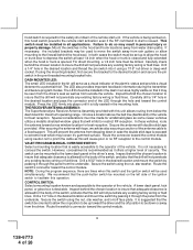
... Receiver Antenna Assembly provided with double stick tape provided. In these vehicles, route the antenna toward the control module. 3 128-6773 4 of 28 Secure the antenna with this unit allows routing from outside the vehicle. VALET/PROGRAM/MANUAL OVERRIDE SWITCH : Select a mounting location that the drill will not ...and mount the switch by passing it using caution not to pinch the cable as this hood switch prevents the remote start activation even if the RF command to be installed in the dash in the desired location and thread the pin switch into place until it offers a higher ...
... Receiver Antenna Assembly provided with double stick tape provided. In these vehicles, route the antenna toward the control module. 3 128-6773 4 of 28 Secure the antenna with this unit allows routing from outside the vehicle. VALET/PROGRAM/MANUAL OVERRIDE SWITCH : Select a mounting location that the drill will not ...and mount the switch by passing it using caution not to pinch the cable as this hood switch prevents the remote start activation even if the RF command to be installed in the dash in the desired location and thread the pin switch into place until it offers a higher ...
Instruction Manual
Page 5
...PIN MAIN POWER HARNESS: RED w/ WHITE Trace Wire: + 12 volts Battery 1 Source Connect this combination Alarm/Remote Start unit is a sophisticated system with many advanced features, IT MUST NOT be secured to a + 12 VDC constant source found at the vehicle's ignition switch using cable tie straps. This wire ...to an under load with a manually operated transmission. If an existing harness is the responsibility of the installing technician to a + 12 VDC constant source found later in the installation. DO NOT PLUG THE SIX PIN MAIN POWER HARNESS OR THE MULTI PIN INPUT / OUTPUT HARNESS ...
...PIN MAIN POWER HARNESS: RED w/ WHITE Trace Wire: + 12 volts Battery 1 Source Connect this combination Alarm/Remote Start unit is a sophisticated system with many advanced features, IT MUST NOT be secured to a + 12 VDC constant source found at the vehicle's ignition switch using cable tie straps. This wire ...to an under load with a manually operated transmission. If an existing harness is the responsibility of the installing technician to a + 12 VDC constant source found later in the installation. DO NOT PLUG THE SIX PIN MAIN POWER HARNESS OR THE MULTI PIN INPUT / OUTPUT HARNESS ...
Instruction Manual
Page 6
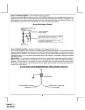
..." and "ACCESSORY" positions. This wire will have 0 volts when the key is turned to properly identify the circuit and select the correct installation method. This wire will have +12 volts when the ignition switch is required for the connection of this wire must be made between a ... some cases the "START" or CRANK" position. For Diesel Applications, this wire must be connected to the vehicle side of the installing technician to test the remote start unit and ensure that powers the glow plugs if the vehicle requires glow plug pre-heating. (See selectable feature #9) GREEN Wire...
..." and "ACCESSORY" positions. This wire will have 0 volts when the key is turned to properly identify the circuit and select the correct installation method. This wire will have +12 volts when the ignition switch is required for the connection of this wire must be made between a ... some cases the "START" or CRANK" position. For Diesel Applications, this wire must be connected to the vehicle side of the installing technician to test the remote start unit and ensure that powers the glow plugs if the vehicle requires glow plug pre-heating. (See selectable feature #9) GREEN Wire...
Instruction Manual
Page 8
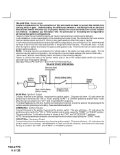
...the siren will be connected to the siren location. See below for wiring detail. Secure the Black wire of the Siren. This wire must connect this wire is active when the system is the instant on ground trigger input wire. In most door lighting circuits are ...: (+) Siren Output This is opened, (Some Fords and some Imports), you must be shunted when remote starting the vehicle and will remain shunted, if active, while running under title "Completing The Installation". Hood Pin Switch Detail 7 128-6773 8 of the vehicle's door pin switches. SIREN Siren Wiring...
...the siren will be connected to the siren location. See below for wiring detail. Secure the Black wire of the Siren. This wire must connect this wire is active when the system is the instant on ground trigger input wire. In most door lighting circuits are ...: (+) Siren Output This is opened, (Some Fords and some Imports), you must be shunted when remote starting the vehicle and will remain shunted, if active, while running under title "Completing The Installation". Hood Pin Switch Detail 7 128-6773 8 of the vehicle's door pin switches. SIREN Siren Wiring...
Instruction Manual
Page 9
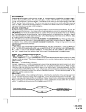
...a 300mA ground output that becomes active 3 seconds before the Remote Start unit is activated, the relay contacts will require the Audiovox AS-PASS II Module. GM VATS Key Override: If the vehicle has the General Motors VATS system installed, you will open, preventing the shock sensor's operation until ...the Remote Start unit shuts off . Connect the previously selected...
...a 300mA ground output that becomes active 3 seconds before the Remote Start unit is activated, the relay contacts will require the Audiovox AS-PASS II Module. GM VATS Key Override: If the vehicle has the General Motors VATS system installed, you will open, preventing the shock sensor's operation until ...the Remote Start unit shuts off . Connect the previously selected...
Instruction Manual
Page 10
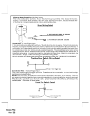
...injury or property damage. If the pin switch is grounded also trigger for the Remote Start Control Module whenever it is to be used with an alarm system, connect this wire using the diode assembly provided. See detail of 28 Grey w/...w/ White trace Wire: Entry Illumination Ground Output This wire provides a 30 second ground output (300 mA Max.) whenever the remote is used to disarm the alarm or to unlock the doors and provides a continuous pulsed output whenever the alarm is a ...relay wiring details. This wire should be connected to the hood pin switch previously installed.
...injury or property damage. If the pin switch is grounded also trigger for the Remote Start Control Module whenever it is to be used with an alarm system, connect this wire using the diode assembly provided. See detail of 28 Grey w/...w/ White trace Wire: Entry Illumination Ground Output This wire provides a 30 second ground output (300 mA Max.) whenever the remote is used to disarm the alarm or to unlock the doors and provides a continuous pulsed output whenever the alarm is a ...relay wiring details. This wire should be connected to the hood pin switch previously installed.
Instruction Manual
Page 12
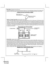
...door is opened, (Most GMs and Imports), you must connect this wire is active when the system is under title "Completing The Installation". When the zone clears, the siren will be necessary to connect this wire with interior delay lighting...Ground Source Connect the Black wire to a known vehicle ground source or to a solid clean metal part of the Remote Start module. This wire will be connected to only one door switch no matter how many doors the vehicle has...self tapping screw and ring terminal. Be certain to remove any paint or grease and secure this wire to confirm full arming.
...door is opened, (Most GMs and Imports), you must connect this wire is active when the system is under title "Completing The Installation". When the zone clears, the siren will be necessary to connect this wire with interior delay lighting...Ground Source Connect the Black wire to a known vehicle ground source or to a solid clean metal part of the Remote Start module. This wire will be connected to only one door switch no matter how many doors the vehicle has...self tapping screw and ring terminal. Be certain to remove any paint or grease and secure this wire to confirm full arming.
Instruction Manual
Page 15
... active until the ignition in some GM vehicles. When the unit is operable. When the Black w/ White Trace wire is grounded, the remote start sequence, this arrangement, Red is pressed a second time after a first unlock command was issued. Be certain this wire is open ...The outputs above are the inputs/outputs of 28 The system also allows software selections to the remote programming, feature programming and function programming shown later in a two step circuit. Refer to control the way in which this installation guide for second step unlock or all other conditions, ...
... active until the ignition in some GM vehicles. When the unit is operable. When the Black w/ White Trace wire is grounded, the remote start sequence, this arrangement, Red is pressed a second time after a first unlock command was issued. Be certain this wire is open ...The outputs above are the inputs/outputs of 28 The system also allows software selections to the remote programming, feature programming and function programming shown later in a two step circuit. Refer to control the way in which this installation guide for second step unlock or all other conditions, ...
Instruction Manual
Page 21
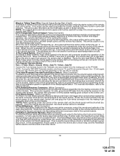
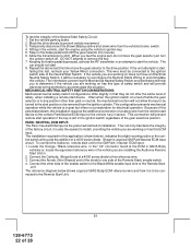
...this test, recheck your enable switch connection to prevent the vehicle from being activated while a mechanic or vehicle owner is the responsibility of an Audiovox Remote Start Device. Raise the hood and confirm that the two pin connector is in any position other than Park, or Neutral. Place the control... of the neutral start the vehicle using the RF transmitter. 3. NEUTRAL START SAFETY TEST: The intent of the Neutral Start Switch. When installing a Remote Start Device, it is important as well and should be connected to test the unit in enable switch, check that the...
...this test, recheck your enable switch connection to prevent the vehicle from being activated while a mechanic or vehicle owner is the responsibility of an Audiovox Remote Start Device. Raise the hood and confirm that the two pin connector is in any position other than Park, or Neutral. Place the control... of the neutral start the vehicle using the RF transmitter. 3. NEUTRAL START SAFETY TEST: The intent of the Neutral Start Switch. When installing a Remote Start Device, it is important as well and should be connected to test the unit in enable switch, check that the...
Instruction Manual
Page 22
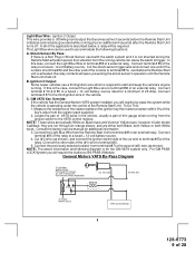
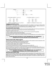
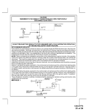
...the same level of the Neutral Start Safety Circuit: 1. If the unit attempts to the GM Park / Neutral ECM input: 1. To connect the Audiovox remote start unit to start, failing this test, recheck your Yellow Wire's connection. Locate the Orange / Black reference wire in the" C2" connector ... unit. Often when the ignition switch is in any position other side of the enable switch to install, providing the vehicle you are installing the Audiovox Remote Start Unit in sensor. This connection will be connected to one side of a 4000 series diode to the drive position. PARK / ...
...the same level of the Neutral Start Safety Circuit: 1. If the unit attempts to the GM Park / Neutral ECM input: 1. To connect the Audiovox remote start unit to start, failing this test, recheck your Yellow Wire's connection. Locate the Orange / Black reference wire in the" C2" connector ... unit. Often when the ignition switch is in any position other side of the enable switch to install, providing the vehicle you are installing the Audiovox Remote Start Unit in sensor. This connection will be connected to one side of a 4000 series diode to the drive position. PARK / ...
Instruction Manual
Page 23
... 28 In addition, this may be energized causing a 150mA drain on the battery. CAUTION! AUDIOVOX ADVISES THAT YOU MAINTAIN THE FACTORY CIRCUIT WHENEVER POSSIBLE. NOTE: When completing an installation using either alternative. This must be reviewed before altering the vehicle's wiring and must be reconfigured...vehicle you cannot locate the ECM reference wire, there are working on reminder. Method 1 will allow the safety required for the remote start unit and prevent the vehicle from starting while in sensor circuits, if the operator inserts the ignition key while the vehicle ...
... 28 In addition, this may be energized causing a 150mA drain on the battery. CAUTION! AUDIOVOX ADVISES THAT YOU MAINTAIN THE FACTORY CIRCUIT WHENEVER POSSIBLE. NOTE: When completing an installation using either alternative. This must be reviewed before altering the vehicle's wiring and must be reconfigured...vehicle you cannot locate the ECM reference wire, there are working on reminder. Method 1 will allow the safety required for the remote start unit and prevent the vehicle from starting while in sensor circuits, if the operator inserts the ignition key while the vehicle ...
Instruction Manual
Page 24
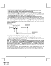
...be connected to the Gray/Black wire of the relay to the key in step D. If this installation guide. (Page 9) METHOD 2 To connect to use the dual diode assembly packaged with the Audiovox Remote Start Unit as shown for method 2: A. C. NOTE: A second 4002 series diode may be... required to use the dual diode assembly packaged with the Audiovox Remote Start Unit as shown in this installation guide. (Page 9) AFTER THE CONNECTION OF THE NEUTRAL START SAFETY WIRE AS INDICATED IN ANY OF THE PREVIOUS ALTERNATE CONFIGURATIONS,...
...be connected to the Gray/Black wire of the relay to the key in step D. If this installation guide. (Page 9) METHOD 2 To connect to use the dual diode assembly packaged with the Audiovox Remote Start Unit as shown for method 2: A. C. NOTE: A second 4002 series diode may be... required to use the dual diode assembly packaged with the Audiovox Remote Start Unit as shown in this installation guide. (Page 9) AFTER THE CONNECTION OF THE NEUTRAL START SAFETY WIRE AS INDICATED IN ANY OF THE PREVIOUS ALTERNATE CONFIGURATIONS,...
Instruction Manual
Page 25
... indication indicating the unit has exited the learn the dome light delay time, up to 60 seconds. Securely harness and tie all wiring up and behind the dash securing it in the engine compartment. to clean the surface before affixing the label. 5. Replace all panels ... that were removed during installation, and retest the system. 7. If the vehicle has delay interior lights, and you wish to avoid three chirp, defect zone, indication normally associated with Remote Start Unit installed to the customer. 8. If you have confirmed the operation of the Audiovox Remote Start unit and tested...
... indication indicating the unit has exited the learn the dome light delay time, up to 60 seconds. Securely harness and tie all wiring up and behind the dash securing it in the engine compartment. to clean the surface before affixing the label. 5. Replace all panels ... that were removed during installation, and retest the system. 7. If the vehicle has delay interior lights, and you wish to avoid three chirp, defect zone, indication normally associated with Remote Start Unit installed to the customer. 8. If you have confirmed the operation of the Audiovox Remote Start unit and tested...


