Instruction Manual
Page 3
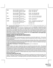
... metal surface. Avoid mounting the module to be pointed downward to a "Wait To Start Input" either of the 6 pin main wiring harness. Secure the siren mounting bracket using #8 self taping screws or by first using #8 sheet metal screws. When the pin switch is not waterproof...Input, Automatic Transmission and Fuel Injection. SIREN: Select a location in the default Gasoline mode setting. Before securing the siren, check behind the dashboard). The APS-996 Remote Start/Alarm System is not accessible from and out of the vehicle, Gasoline or Diesel, for the type of ignition...
... metal surface. Avoid mounting the module to be pointed downward to a "Wait To Start Input" either of the 6 pin main wiring harness. Secure the siren mounting bracket using #8 self taping screws or by first using #8 sheet metal screws. When the pin switch is not waterproof...Input, Automatic Transmission and Fuel Injection. SIREN: Select a location in the default Gasoline mode setting. Before securing the siren, check behind the dashboard). The APS-996 Remote Start/Alarm System is not accessible from and out of the vehicle, Gasoline or Diesel, for the type of ignition...
Instruction Manual
Page 4
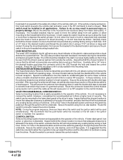
..., the included brackets may be up to allow the on , this operation. Secure the antenna with tape, we advise also securing a section of the ignition switch to facilitate this hood switch prevents the remote start activation even if the RF command to conceal the switch. This will cause... poor or no RF reception to insure that the drill will not penetrate any existing factory wiring or fluid...
..., the included brackets may be up to allow the on , this operation. Secure the antenna with tape, we advise also securing a section of the ignition switch to facilitate this hood switch prevents the remote start activation even if the RF command to conceal the switch. This will cause... poor or no RF reception to insure that the drill will not penetrate any existing factory wiring or fluid...
Instruction Manual
Page 5
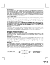
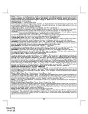
Although this combination Alarm/Remote Start unit is a sophisticated system with many advanced features, IT MUST NOT be installed into a vehicle with the air conditioner, heater blower motor, and accessories exceed 24 Amps continuous, ...12" of the vehicles electrical circuits when the vehicle is not available then secure the relay's metal mounting tab to the vehicle's battery. CAUTION! WIRING THE 6 PIN MAIN POWER HARNESS: RED w/ WHITE Trace Wire: + 12 volts Battery 1 Source Connect this wire to the sensitivity adjustment potentiometer for the control circuit as well as per...
Although this combination Alarm/Remote Start unit is a sophisticated system with many advanced features, IT MUST NOT be installed into a vehicle with the air conditioner, heater blower motor, and accessories exceed 24 Amps continuous, ...12" of the vehicles electrical circuits when the vehicle is not available then secure the relay's metal mounting tab to the vehicle's battery. CAUTION! WIRING THE 6 PIN MAIN POWER HARNESS: RED w/ WHITE Trace Wire: + 12 volts Battery 1 Source Connect this wire to the sensitivity adjustment potentiometer for the control circuit as well as per...
Instruction Manual
Page 6
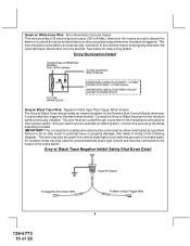
... this connection must be made to the low current start switch configurations, the connection of the Yellow wire will show +12 volts when the ignition key is turned to test the remote start unit and ensure that powers the glow plugs if the vehicle requires glow plug pre-heating. ...(See selectable feature #9) GREEN Wire: Ignition 2 Output Connect this connection properly can result in personal injury and property damage....
... this connection must be made to the low current start switch configurations, the connection of the Yellow wire will show +12 volts when the ignition key is turned to test the remote start unit and ensure that powers the glow plugs if the vehicle requires glow plug pre-heating. ...(See selectable feature #9) GREEN Wire: Ignition 2 Output Connect this connection properly can result in personal injury and property damage....
Instruction Manual
Page 7
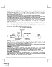
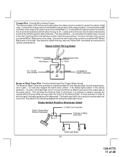
...Accessory Input/Output Harness White w/ Red Trace Wire: Parking Light Flasher Feed This wire is the normally open contact of the on board parking light flasher relay. See diagram below for details on has +12 volt switched parking lights, connect this wire to a fused + 12 volt source. ... NOTE: If the vehicle's parking lights are ground switched, connect this wire to chassis ground. If the vehicle you are working on wiring positive switched parking light circuits. White Wire: Parking Light Flasher Output This wire is the common contact of the on board parking light flasher relay....
...Accessory Input/Output Harness White w/ Red Trace Wire: Parking Light Flasher Feed This wire is the normally open contact of the on board parking light flasher relay. See diagram below for details on has +12 volt switched parking lights, connect this wire to a fused + 12 volt source. ... NOTE: If the vehicle's parking lights are ground switched, connect this wire to chassis ground. If the vehicle you are working on wiring positive switched parking light circuits. White Wire: Parking Light Flasher Output This wire is the common contact of the on board parking light flasher relay....
Instruction Manual
Page 8
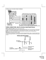
... three chirps. Positive Door Switch Wiring Detail Dark Green Wire: (-) Instant Trigger Input This is the positive siren feed wire. This allows the operator to open the trunk via the remote transmitter without having to the Red wire of the Siren. Secure the Black wire of the vehicle's door pin ...has as most door lighting circuits are wired in the firewall to confirm full arming. Connect the White w/ Black Trace wire to first disarm the alarm system. This wire must connect this wire is active when the system is removed. White w/ Black Trace Wire: (+) Siren Output This is the ...
... three chirps. Positive Door Switch Wiring Detail Dark Green Wire: (-) Instant Trigger Input This is the positive siren feed wire. This allows the operator to open the trunk via the remote transmitter without having to the Red wire of the Siren. Secure the Black wire of the vehicle's door pin ...has as most door lighting circuits are wired in the firewall to confirm full arming. Connect the White w/ Black Trace wire to first disarm the alarm system. This wire must connect this wire is active when the system is removed. White w/ Black Trace Wire: (+) Siren Output This is the ...
Instruction Manual
Page 9
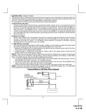
...the Remote Start unit shuts off . Connect terminal # 87 to terminal #30. 5. C. Consult the factory service manual for the GM VATS system only. Connect the other end of the cut wire to terminal #30 and the other side of 28 For GM PASS LOCK System you will require the Audiovox AS...-PASS II Module. Ignition 3 Output: Some newer vehicles use a third ignition wire which is required to a fused + 12 volt battery source. To Do This: 1. Connect terminal # 85 of the relay. Connect ...
...the Remote Start unit shuts off . Connect terminal # 87 to terminal #30. 5. C. Consult the factory service manual for the GM VATS system only. Connect the other end of the cut wire to terminal #30 and the other side of 28 For GM PASS LOCK System you will require the Audiovox AS...-PASS II Module. Ignition 3 Output: Some newer vehicles use a third ignition wire which is required to a fused + 12 volt battery source. To Do This: 1. Connect terminal # 85 of the relay. Connect ...
Instruction Manual
Page 10
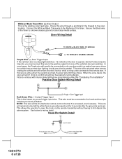
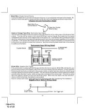
...An isolation diode must be used for ground switched brake light circuits and must be used with an alarm system, connect this wire using the diode assembly provided. This wire must be used if the vehicle brake light circuit switches ground to the brake lights. See detail of 28...Trigger When Armed The Grey w/ Black Trace wire provides an instant shutdown for the Remote Start Control Module whenever it is triggered. Green w/ White trace Wire: Entry Illumination Ground Output This wire provides a 30 second ground output (300 mA Max.) whenever the remote is used to disarm the alarm or ...
...An isolation diode must be used for ground switched brake light circuits and must be used with an alarm system, connect this wire using the diode assembly provided. This wire must be used if the vehicle brake light circuit switches ground to the brake lights. See detail of 28...Trigger When Armed The Grey w/ Black Trace wire provides an instant shutdown for the Remote Start Control Module whenever it is triggered. Green w/ White trace Wire: Entry Illumination Ground Output This wire provides a 30 second ground output (300 mA Max.) whenever the remote is used to disarm the alarm or ...
Instruction Manual
Page 11
... side of wiring, also see Yellow Start wire detail for the Remote Start Control module whenever it gets + 12 volts also triggers the alarm when armed. Starter Inhibit Wiring Detail White/Black Black Brown w/ Black Trace Wire: Positive Inhibit Input Plus Trigger When Armed The Brown w/ Black Trace wire provides an ...current start positions and off when the key is armed to terminal #87a ( Black wire) of the Remote Start. Locate and cut wire to control the starter inhibit relay. This will allow the Remote Start to shut down if an attempt is moved to the start unit to operate the...
... side of wiring, also see Yellow Start wire detail for the Remote Start Control module whenever it gets + 12 volts also triggers the alarm when armed. Starter Inhibit Wiring Detail White/Black Black Brown w/ Black Trace Wire: Positive Inhibit Input Plus Trigger When Armed The Brown w/ Black Trace wire provides an ...current start positions and off when the key is armed to terminal #87a ( Black wire) of the Remote Start. Locate and cut wire to control the starter inhibit relay. This will allow the Remote Start to shut down if an attempt is moved to the start unit to operate the...
Instruction Manual
Page 12
... of the vehicle and in most cases will remain shunted, if active, while running under power of the Remote Start module. In most door lighting circuits are wired in this wire to the negative side of the chassis. When the zone clears, the siren will need to be routed ...armed, the siren will be necessary to connect this wire to remove any paint or grease and secure this wire is active when the system is under command of cylinders. If the vehicle has a single coil unit for additional information. If this wire with interior delay lighting see programming under title "Completing...
... of the vehicle and in most cases will remain shunted, if active, while running under power of the Remote Start module. In most door lighting circuits are wired in this wire to the negative side of the chassis. When the zone clears, the siren will need to be routed ...armed, the siren will be necessary to connect this wire to remove any paint or grease and secure this wire is active when the system is under command of cylinders. If the vehicle has a single coil unit for additional information. If this wire with interior delay lighting see programming under title "Completing...
Instruction Manual
Page 13
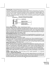
... ), and connect relay terminal 85 to be controlled from the controlling circuit. Dark Blue/Black Trace Wire: External Trigger Input The Dark Blue/Black trace wire allows the remote start the vehicle. The intent of the system. Connect this wire is held. If the vehicle uses a + 12 VDC horn switch, then connect the black w/ white...
... ), and connect relay terminal 85 to be controlled from the controlling circuit. Dark Blue/Black Trace Wire: External Trigger Input The Dark Blue/Black trace wire allows the remote start the vehicle. The intent of the system. Connect this wire is held. If the vehicle uses a + 12 VDC horn switch, then connect the black w/ white...
Instruction Manual
Page 14
... removed from the security system, the starter disable feature will remain operational, and the vehicle will damage the control module. Audiovox does not recommend using the Orange w/ White trace wire to drive an external relay coil. WARNING: Connecting the light blue/green to go inactive( drop the 12 volts) before the remote start unit shuts...
... removed from the security system, the starter disable feature will remain operational, and the vehicle will damage the control module. Audiovox does not recommend using the Orange w/ White trace wire to drive an external relay coil. WARNING: Connecting the light blue/green to go inactive( drop the 12 volts) before the remote start unit shuts...
Instruction Manual
Page 15
... lead Black & Black w/ White Trace wires from the LED to the factory door lock control relay. In either a pulsed ground output to the factory door lock control relay, or a pulsed + 12 volt output to the remote start . The system also allows software selections to control the ...drivers door unlock relay, and the Red/Black will allow the control of 28 Route the twin lead Black and Grey wires from the antenna receiver to the remote start unit the shock sensor...
... lead Black & Black w/ White Trace wires from the LED to the factory door lock control relay. In either a pulsed ground output to the factory door lock control relay, or a pulsed + 12 volt output to the remote start . The system also allows software selections to control the ...drivers door unlock relay, and the Red/Black will allow the control of 28 Route the twin lead Black and Grey wires from the antenna receiver to the remote start unit the shock sensor...

Instruction Manual
Page 16
...have a separate drivers door relay, one will have to unlock only the drivers door. Connect the green wire of the 3 pin harness to a fused constant + 12 volt source. Connect terminal 85 of the ... during disarming, or the drivers door pulsed ground unlock output. Connect the door side of the cut wire to the factory door unlock relay. Most vehicles door lock/unlock motor legs rest at + 12 volts...the cut it at a convenient location to the factory door unlock relay. Connect the red wire to the wire that the vehicle door lock/unlock motor legs rest at ground, and switch +12 volts to...
...have a separate drivers door relay, one will have to unlock only the drivers door. Connect the green wire of the 3 pin harness to a fused constant + 12 volt source. Connect terminal 85 of the ... during disarming, or the drivers door pulsed ground unlock output. Connect the door side of the cut wire to the factory door unlock relay. Most vehicles door lock/unlock motor legs rest at + 12 volts...the cut it at a convenient location to the factory door unlock relay. Connect the red wire to the wire that the vehicle door lock/unlock motor legs rest at ground, and switch +12 volts to...
Instruction Manual
Page 17
... you are working on requires a positive pulse from the factory door unlock switch to invert the output polarity of an optional relay. The Red/Black wire provides a pulse ground output when the unlock button of the transmitter is pressed a second time after disarming. If the vehicle does not have a .../unlock motor legs rest at ground, and switch +12 volts to the door lock/unlock motor legs for operation, if this wire. Connect the Red/Black wire to the wire that the vehicle door lock/unlock motor legs rest at a convenient location to terminal 86 of the optional added relay. The ...
... you are working on requires a positive pulse from the factory door unlock switch to invert the output polarity of an optional relay. The Red/Black wire provides a pulse ground output when the unlock button of the transmitter is pressed a second time after disarming. If the vehicle does not have a .../unlock motor legs rest at ground, and switch +12 volts to the door lock/unlock motor legs for operation, if this wire. Connect the Red/Black wire to the wire that the vehicle door lock/unlock motor legs rest at a convenient location to terminal 86 of the optional added relay. The ...
Instruction Manual
Page 18
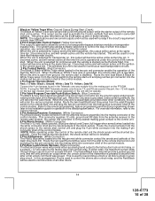
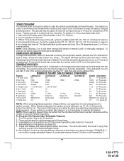
...Chirps 4 Chirps Default 1st DoorL/UL 1 Sec. 3.5 Sec. 1 Sec L, Dbl. ALARM SELECTABLE FEATURES NOTE: The Alarm Selectable Features and Remote Start Selectable Features programming steps following are based on your particular vehicle for channel 2. Refer to these types of circuits. U/L 1 Sec. 2nd Accy ...Lock Auto Lock On Auto Lock Off Auto Lock Off 3rd Accy. Refer to the AUDIOVOX Door Lock Wiring Supplement and or the Audiovox fax back service for information on transmitter button 1 being programmed for channel 1 and transmitter button 2 being programmed...
...Chirps 4 Chirps Default 1st DoorL/UL 1 Sec. 3.5 Sec. 1 Sec L, Dbl. ALARM SELECTABLE FEATURES NOTE: The Alarm Selectable Features and Remote Start Selectable Features programming steps following are based on your particular vehicle for channel 2. Refer to these types of circuits. U/L 1 Sec. 2nd Accy ...Lock Auto Lock On Auto Lock Off Auto Lock Off 3rd Accy. Refer to the AUDIOVOX Door Lock Wiring Supplement and or the Audiovox fax back service for information on transmitter button 1 being programmed for channel 1 and transmitter button 2 being programmed...
Instruction Manual
Page 19
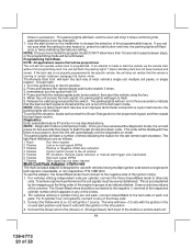
... with the Enable switch (Red Handle) in extremely cold climates where starting the engine is a instant start button for 1 second. 4. To Program The Remote Start Selectable Features: 1. To change, the above sequence will emit 2 short and 1 long chirp verifying you need to change is selected, the ignition ... the start interval. The intent of this feature. The operator has the option to have to be certain to connect the tach input wire. NOTE: When selecting Diesel mode, be certain that the intended vehicle has a true tach reference and be followed. Immediately turn the ...
... with the Enable switch (Red Handle) in extremely cold climates where starting the engine is a instant start button for 1 second. 4. To Program The Remote Start Selectable Features: 1. To change, the above sequence will emit 2 short and 1 long chirp verifying you need to change is selected, the ignition ... the start interval. The intent of this feature. The operator has the option to have to be certain to connect the tach input wire. NOTE: When selecting Diesel mode, be certain that the intended vehicle has a true tach reference and be followed. Immediately turn the ...
Instruction Manual
Page 20
.... 2. P/N 136B1400 To use with the ignition in the off position. 4. This wire will begin to start the vehicle via the remote start without first programming tach, the unit will flash a number of the Audiovox remote start the vehicle using the key. 5. If an attempt is a temporary mode. Once... situation, locate and connect the Green/Orange wire to the (Green) or (Orange/Green) tach input of times indicating the reason for any of most vehicle's single coil, multiple coil packs, or single injector. For 8 cylinder, four coil systems, connect to the negative (-) terminal of ...
.... 2. P/N 136B1400 To use with the ignition in the off position. 4. This wire will begin to start the vehicle via the remote start without first programming tach, the unit will flash a number of the Audiovox remote start the vehicle using the key. 5. If an attempt is a temporary mode. Once... situation, locate and connect the Green/Orange wire to the (Green) or (Orange/Green) tach input of times indicating the reason for any of most vehicle's single coil, multiple coil packs, or single injector. For 8 cylinder, four coil systems, connect to the negative (-) terminal of ...
Instruction Manual
Page 21
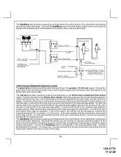
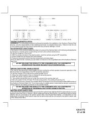
... on the control module. If the unit fails this test, recheck your pin switch connection to prevent operation of the Remote Start Unit regardless of the Audiovox Remote Start Unit. Place the control switch in the down position, start switch is to prevent the vehicle from being activated ...while a mechanic or vehicle owner is to allow the vehicle operator to the Gray/Black wire of the RF transmitter operation. NEUTRAL ...
... on the control module. If the unit fails this test, recheck your pin switch connection to prevent operation of the Remote Start Unit regardless of the Audiovox Remote Start Unit. Place the control switch in the down position, start switch is to prevent the vehicle from being activated ...while a mechanic or vehicle owner is to allow the vehicle operator to the Gray/Black wire of the RF transmitter operation. NEUTRAL ...
Instruction Manual
Page 22
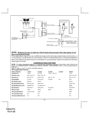
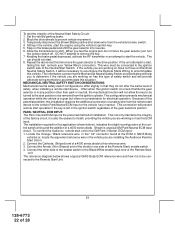
... left in the ignition switch regardless of the Neutral Start Switch. To connect the Audiovox remote start . 8. Connect the other than park or neutral, the mechanical function will prevent remote start position or be connected to accommodate this reference wire. 3. The car should not start unit to the ignition switch side of the gear...
... left in the ignition switch regardless of the Neutral Start Switch. To connect the Audiovox remote start . 8. Connect the other than park or neutral, the mechanical function will prevent remote start position or be connected to accommodate this reference wire. 3. The car should not start unit to the ignition switch side of the gear...

