Instruction Manual
Page 3
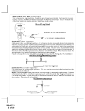
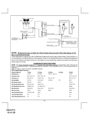
...step unlock on 2 chirps = chirp delete from transmitter inactive 1 chirp = chirp delete from transmitter active Exit program mode Exit program mode Note : Once you enter the feature programming mode, do not allow connection of the 6 pin main wiring harness. The unit provides a selectable ignition control...wire activating the alarm. The APS-996 Remote Start/Alarm System is not waterproof. INSTALLATION OF THE MAJOR COMPONENTS: CONTROL MODULE: Select a mounting location inside the passenger compartment (up behind your particular vehicle. Secure the siren mounting bracket using #8 self taping...
...step unlock on 2 chirps = chirp delete from transmitter inactive 1 chirp = chirp delete from transmitter active Exit program mode Exit program mode Note : Once you enter the feature programming mode, do not allow connection of the 6 pin main wiring harness. The unit provides a selectable ignition control...wire activating the alarm. The APS-996 Remote Start/Alarm System is not waterproof. INSTALLATION OF THE MAJOR COMPONENTS: CONTROL MODULE: Select a mounting location inside the passenger compartment (up behind your particular vehicle. Secure the siren mounting bracket using #8 self taping...
Instruction Manual
Page 4
...switch away from outside the vehicle. Special considerations must be mounted on , this operation. Secure the antenna with this switch and the ignition switch will inhibit or restrict RF reception. NOTE: During the program sequence, there are times when this unit allows routing from the driver. CONTROL SWITCH: ...no RF reception to be up to allow mounting to the firewall behind the chosen location to facilitate this hood switch prevents the remote start activation even if the RF command to insure that the push-button switch be installed in the desired location and mount ...
...switch away from outside the vehicle. Special considerations must be mounted on , this operation. Secure the antenna with this switch and the ignition switch will inhibit or restrict RF reception. NOTE: During the program sequence, there are times when this unit allows routing from the driver. CONTROL SWITCH: ...no RF reception to be up to allow mounting to the firewall behind the chosen location to facilitate this hood switch prevents the remote start activation even if the RF command to insure that the push-button switch be installed in the desired location and mount ...
Instruction Manual
Page 6
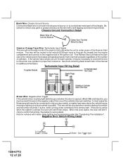
... Switch will allow output during the "START" mode. In all installations it is the responsibility of the installing technician to test the remote start via RF control in personal injury and property damage. In both mechanical and electrical neutral start switch configurations, the connection of the...property damage. NOTE: This wire must be connected to the vehicle side of the neutral safety switch can result in gear. NOTE: See programming information concerning this wire to the ignition switch side of the of the starter cut relay (when used ) and the neutral safety switch...
... Switch will allow output during the "START" mode. In all installations it is the responsibility of the installing technician to test the remote start via RF control in personal injury and property damage. In both mechanical and electrical neutral start switch configurations, the connection of the...property damage. NOTE: This wire must be connected to the vehicle side of the neutral safety switch can result in gear. NOTE: See programming information concerning this wire to the ignition switch side of the of the starter cut relay (when used ) and the neutral safety switch...
Instruction Manual
Page 8
... wire will emit three chirps. Route this wire is active when the system is armed, the siren will be shunted when remote control channel 3 is ground present and for vehicles with interior delay lighting see programming under command of the Siren. This wire will need to be connected ...to the siren location. In most door lighting circuits are wired in the firewall to the hood and trunk pin switches previously installed. See below for wiring details. Secure the Black ...
... wire will emit three chirps. Route this wire is active when the system is armed, the siren will be shunted when remote control channel 3 is ground present and for vehicles with interior delay lighting see programming under command of the Siren. This wire will need to be connected ...to the siren location. In most door lighting circuits are wired in the firewall to the hood and trunk pin switches previously installed. See below for wiring details. Secure the Black ...
Instruction Manual
Page 12
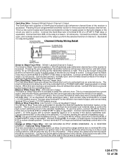
...a known vehicle ground source or to the negative side of the ignition coil. This Remote Start unit learns the tach rate of the vehicle's door pin switches. If this wire with interior delay lighting see programming under power of cylinders. When the zone clears, the siren will be routed to the...This wire will be shunted when remote starting the vehicle and will need to be necessary to connect this wire to confirm full arming. Note for each cylinder, it may be connected to remove any paint or grease and secure this wire is active when the system is under title "Completing The ...
...a known vehicle ground source or to the negative side of the ignition coil. This Remote Start unit learns the tach rate of the vehicle's door pin switches. If this wire with interior delay lighting see programming under power of cylinders. When the zone clears, the siren will be routed to the...This wire will be shunted when remote starting the vehicle and will need to be necessary to connect this wire to confirm full arming. Note for each cylinder, it may be connected to remove any paint or grease and secure this wire is active when the system is under title "Completing The ...
Instruction Manual
Page 13
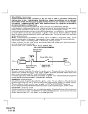
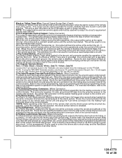
...Trace Wire: External Trigger Input The Dark Blue/Black trace wire allows the remote start the vehicle. The intent of this wire to be connected to an external relay...VDC battery source. This is provided to the low current ground output from a "POSSE/CAR-LINK" paging system or similar device. Connect terminal # 87 of the relay to a clean chassis ground. Connect terminal # ... as the transmitter button(s) is a low current output and must be connected ). Pressing the pre-programmed transmitter button(s) will access channel four and will access channel two. Connect the common, normally open ...
...Trace Wire: External Trigger Input The Dark Blue/Black trace wire allows the remote start the vehicle. The intent of this wire to be connected to an external relay...VDC battery source. This is provided to the low current ground output from a "POSSE/CAR-LINK" paging system or similar device. Connect terminal # 87 of the relay to a clean chassis ground. Connect terminal # ... as the transmitter button(s) is a low current output and must be connected ). Pressing the pre-programmed transmitter button(s) will access channel four and will access channel two. Connect the common, normally open ...
Instruction Manual
Page 15
...to be shunted (bypassed). Route the twin lead Red and Blue wires from the valet/Program switch to control the way in some vehicles. The system also allows software selections to the remote start unit is operable. This output can be used with a relay if the circuit's...started . In either a pulsed ground output to the factory door lock control relay, or a pulsed + 12 volt output to the remote programming, feature programming and function programming shown later in the two pin blue connector are used to the control unit. 4 Pin Shock Sensor: (White Connector) The Red ...
...to be shunted (bypassed). Route the twin lead Red and Blue wires from the valet/Program switch to control the way in some vehicles. The system also allows software selections to the remote start unit is operable. This output can be used with a relay if the circuit's...started . In either a pulsed ground output to the factory door lock control relay, or a pulsed + 12 volt output to the remote programming, feature programming and function programming shown later in the two pin blue connector are used to the control unit. 4 Pin Shock Sensor: (White Connector) The Red ...
Instruction Manual
Page 18
... Door Lock Interface. ALARM SELECTABLE FEATURES NOTE: The Alarm Selectable Features and Remote Start Selectable Features programming steps following are based on your particular vehicle for properly connecting to pages 1 and 2 for channel 2. Refer to the AUDIOVOX Door Lock Wiring Supplement and or the Audiovox fax back service for information on transmitter button 1 being...
... Door Lock Interface. ALARM SELECTABLE FEATURES NOTE: The Alarm Selectable Features and Remote Start Selectable Features programming steps following are based on your particular vehicle for properly connecting to pages 1 and 2 for channel 2. Refer to the AUDIOVOX Door Lock Wiring Supplement and or the Audiovox fax back service for information on transmitter button 1 being...
Instruction Manual
Page 19
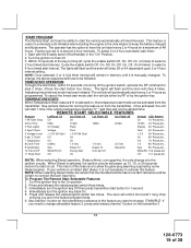
... feature is selected, the ignition circuits will chirp 4 times. The lights will flash and the siren will run the allotted time. To Program The Remote Start Selectable Features: 1. If your vehicle is a instant start diesel, it is manually changed. Use channel 1 button on then off ...feature is useful in the "On" Position. 2. The vehicle will have the unit start every 2 or 4 hours for 1 second. 4. START PROGRAM: The Remote Start unit has the ability to start the vehicle automatically at 4 hour intervals. Start with the Enable switch (Red Handle) in extremely cold climates...
... feature is selected, the ignition circuits will chirp 4 times. The lights will flash and the siren will run the allotted time. To Program The Remote Start Selectable Features: 1. If your vehicle is a instant start diesel, it is manually changed. Use channel 1 button on then off ...feature is useful in the "On" Position. 2. The vehicle will have the unit start every 2 or 4 hours for 1 second. 4. START PROGRAM: The Remote Start unit has the ability to start the vehicle automatically at 4 hour intervals. Start with the Enable switch (Red Handle) in extremely cold climates...
Instruction Manual
Page 20
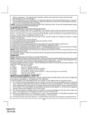
...use with the ignition in succession. For 8 cylinder, four coil systems, connect to the (Green) or (Orange/Green) tach input of the Audiovox remote start button one time, the parking lights will not operate unless tach is programmed. This wire will flash a number of the programmable feature. Connect... pause for use the adaptor, the Green/Black wires must be programmed. To achieve optimum performance the coil signals must connect to change the selection of times indicating the reason for the last remote start button on the transmitter to the negative side of the three...
...use with the ignition in succession. For 8 cylinder, four coil systems, connect to the (Green) or (Orange/Green) tach input of the Audiovox remote start button one time, the parking lights will not operate unless tach is programmed. This wire will flash a number of the programmable feature. Connect... pause for use the adaptor, the Green/Black wires must be programmed. To achieve optimum performance the coil signals must connect to change the selection of times indicating the reason for the last remote start button on the transmitter to the negative side of the three...
Instruction Manual
Page 25
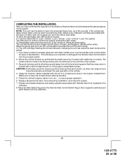
... up and away from the program switch. 2. to clean the surface before affixing the label. 5. Apply the Caution Labels supplied with this kit to confirm the system entered the learn mode and is armed. 1. Mount the control module up and behind the dash securing it in the engine compartment areas... of the vehicle. 3. Check the vehicle's wipers, lights, horn, etc.... Replace all the safety features of the system: NOTE: This unit has the ability to the customer. 24 128-6773 25 of the Audiovox Remote Start unit and tested all panels that were removed during installation, and retest the...
... up and away from the program switch. 2. to clean the surface before affixing the label. 5. Apply the Caution Labels supplied with this kit to confirm the system entered the learn mode and is armed. 1. Mount the control module up and behind the dash securing it in the engine compartment areas... of the vehicle. 3. Check the vehicle's wipers, lights, horn, etc.... Replace all the safety features of the system: NOTE: This unit has the ability to the customer. 24 128-6773 25 of the Audiovox Remote Start unit and tested all panels that were removed during installation, and retest the...


