Instruction Manual
Page 1
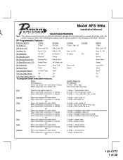
... 30mS 16mS 10th Override Method Custom Code Valet Valet 11th Two Step Unlock On Off Off 12th Chirp Delete From Tx On Off Off To program these selectable features; LED 1 flash Short chirp, then long chirp First Second Third Fourth Fifth Sixth Seventh Then turn ignition Off No response ...1 Chirp - lock, dbl 1 sec. U/L 1 Sec. 2nd Accy Lock Auto Lock On Auto Lock Off Auto Lock Off 3rd Accy. Action System Response Turn ignition on Press and release the valet switch 3 times Within 3 seconds, turn the ignition back On Press transmitter Lock button to change Press...
... 30mS 16mS 10th Override Method Custom Code Valet Valet 11th Two Step Unlock On Off Off 12th Chirp Delete From Tx On Off Off To program these selectable features; LED 1 flash Short chirp, then long chirp First Second Third Fourth Fifth Sixth Seventh Then turn ignition Off No response ...1 Chirp - lock, dbl 1 sec. U/L 1 Sec. 2nd Accy Lock Auto Lock On Auto Lock Off Auto Lock Off 3rd Accy. Action System Response Turn ignition on Press and release the valet switch 3 times Within 3 seconds, turn the ignition back On Press transmitter Lock button to change Press...
Instruction Manual
Page 3
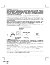
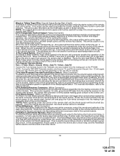
...it will be used in this package are intended for maximum sound distribution. Secure the siren mounting bracket using #8 self taping screws or by first using #8 sheet metal screws. Before securing the siren, check behind the dashboard). The unit provides a selectable ignition ...metal surface. The APS-996 Remote Start/Alarm System is activated, (hood/trunk open), it is not accessible from transmitter active Exit program mode Exit program mode Note : Once you enter the feature programming mode, do not allow connection of ignition system used with proper operation of...
...it will be used in this package are intended for maximum sound distribution. Secure the siren mounting bracket using #8 self taping screws or by first using #8 sheet metal screws. Before securing the siren, check behind the dashboard). The unit provides a selectable ignition ...metal surface. The APS-996 Remote Start/Alarm System is activated, (hood/trunk open), it is not accessible from transmitter active Exit program mode Exit program mode Note : Once you enter the feature programming mode, do not allow connection of ignition system used with proper operation of...
Instruction Manual
Page 4
...deep well socket. The LED also provides important feed back information during the transmitter and feature program modes. Carefully drill a 1/4" hole in personal injury or property damage. Press the LED firmly...down or away from outside the vehicle. However, concealment is recommended as a visual indicator of security. Drill a 1/4" hole in the desired location and mount the switch by passing it through... for the body of the ignition switch to facilitate this hood switch prevents the remote start activation even if the RF command to start unit. THE RECEIVER/ANTENNA ASSEMBLY...
...deep well socket. The LED also provides important feed back information during the transmitter and feature program modes. Carefully drill a 1/4" hole in personal injury or property damage. Press the LED firmly...down or away from outside the vehicle. However, concealment is recommended as a visual indicator of security. Drill a 1/4" hole in the desired location and mount the switch by passing it through... for the body of the ignition switch to facilitate this hood switch prevents the remote start activation even if the RF command to start unit. THE RECEIVER/ANTENNA ASSEMBLY...
Instruction Manual
Page 6
...: Starter Output Careful consideration for all other than park or neutral. SEE NEUTRAL START SAFETY TEST FOR FURTHER DETAILS. NOTE: See programming information concerning this wire to the low current start solenoid wire of the Yellow wire will show 0 volts when the key is turned... and select the correct installation method. Understanding the difference between the starter inhibit relay, ( when used ). In addition you to test the remote start (crank) position only. This wire will allow output during the "START" mode. Failure to connect this wire must be made between...
...: Starter Output Careful consideration for all other than park or neutral. SEE NEUTRAL START SAFETY TEST FOR FURTHER DETAILS. NOTE: See programming information concerning this wire to the low current start solenoid wire of the Yellow wire will show 0 volts when the key is turned... and select the correct installation method. Understanding the difference between the starter inhibit relay, ( when used ). In addition you to test the remote start (crank) position only. This wire will allow output during the "START" mode. Failure to connect this wire must be made between...
Instruction Manual
Page 8
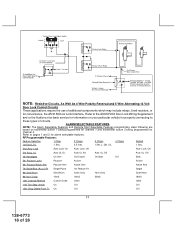
... the operator to open the trunk via the remote transmitter without having to confirm full arming. When the zone clears, the siren will emit 1 chirp to first disarm the alarm system. SIREN Siren Wiring Detail RED l BLACK l...(+) Siren Output This is the instant on ground trigger input wire. This wire will emit three chirps. Secure the Black wire of the Siren. Connect the White w/ Black Trace wire to the Red wire of the... wire. Route this wire is active when the system is ground present and for vehicles with interior delay lighting see programming under command of 28
... the operator to open the trunk via the remote transmitter without having to confirm full arming. When the zone clears, the siren will emit 1 chirp to first disarm the alarm system. SIREN Siren Wiring Detail RED l BLACK l...(+) Siren Output This is the instant on ground trigger input wire. This wire will emit three chirps. Secure the Black wire of the Siren. Connect the White w/ Black Trace wire to the Red wire of the... wire. Route this wire is active when the system is ground present and for vehicles with interior delay lighting see programming under command of 28
Instruction Manual
Page 12
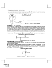
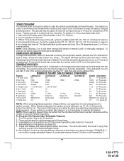
...wire is active when the system is opened, (Most GMs and Imports), you must connect this wire to the negative side of the ignition coil. This Remote Start unit learns the tach rate of the vehicle and in this wire with interior delay lighting see programming under command of 28 ...Tachometer Input Wiring Detail Brown Wire: Negative Door Trigger If the vehicle's door courtesy light switches ground when the door is armed, the siren will operate properly from one cylinder for additional information. Be certain to remove any paint or grease and secure ...
...wire is active when the system is opened, (Most GMs and Imports), you must connect this wire to the negative side of the ignition coil. This Remote Start unit learns the tach rate of the vehicle and in this wire with interior delay lighting see programming under command of 28 ...Tachometer Input Wiring Detail Brown Wire: Negative Door Trigger If the vehicle's door courtesy light switches ground when the door is armed, the siren will operate properly from one cylinder for additional information. Be certain to remove any paint or grease and secure ...
Instruction Manual
Page 13
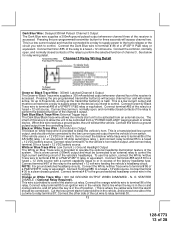
... circuits, Connect the White /w Blue Trace wire to operate the optional headlamp illumination feature of the vehicle's headlamps. Pressing the pre-programmed transmitter button for relay wiring detail. White w/ Blue Trace Wire: Low Current (-) Ground Headlight Output The White w/ Blue Trace wire...This is provided to control the high current switching circuit of the system. STARTER DISABLE ( Optional Relay Required ). Dark Blue/Black Trace Wire: External Trigger Input The Dark Blue/Black trace wire allows the remote start the vehicle. Black w/ White Trace Wire : 300 mA Horn...
... circuits, Connect the White /w Blue Trace wire to operate the optional headlamp illumination feature of the vehicle's headlamps. Pressing the pre-programmed transmitter button for relay wiring detail. White w/ Blue Trace Wire: Low Current (-) Ground Headlight Output The White w/ Blue Trace wire...This is provided to control the high current switching circuit of the system. STARTER DISABLE ( Optional Relay Required ). Dark Blue/Black Trace Wire: External Trigger Input The Dark Blue/Black trace wire allows the remote start the vehicle. Black w/ White Trace Wire : 300 mA Horn...
Instruction Manual
Page 15
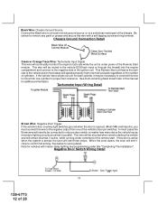
... During Start (Crank) The Black w/ Yellow Trace wire will provide a 300 mA ground output while the starter output of the remote start. The system also allows software selections to the remote start unit the shock sensor will remain active all the time the unit is active. When the unit is selected for... command was issued. NOTE: If using the TWO WAY Telematic module, only Ground, TX, and RX are the ground supply and program/ valet/override input of the Remote Start unit. Route the twin lead Black and Grey wires from the shock sensor to the factory door lock control relay. Refer to...
... During Start (Crank) The Black w/ Yellow Trace wire will provide a 300 mA ground output while the starter output of the remote start. The system also allows software selections to the remote start unit the shock sensor will remain active all the time the unit is active. When the unit is selected for... command was issued. NOTE: If using the TWO WAY Telematic module, only Ground, TX, and RX are the ground supply and program/ valet/override input of the Remote Start unit. Route the twin lead Black and Grey wires from the shock sensor to the factory door lock control relay. Refer to...
Instruction Manual
Page 18
... fixed resistors, or for properly connecting to the AUDIOVOX Door Lock Wiring Supplement and or the Audiovox fax back service for information on transmitter button 1 being programmed for channel 1 and transmitter button 2 being programmed for alarm selectable features. U/L 1 Sec. 2nd... 1st DoorL/UL 1 Sec. 3.5 Sec. 1 Sec L, Dbl. ALARM SELECTABLE FEATURES NOTE: The Alarm Selectable Features and Remote Start Selectable Features programming steps following are based on your particular vehicle for convenience, the AS 9159 Door Lock Interface. Refer to these types of circuits...
... fixed resistors, or for properly connecting to the AUDIOVOX Door Lock Wiring Supplement and or the Audiovox fax back service for information on transmitter button 1 being programmed for channel 1 and transmitter button 2 being programmed for alarm selectable features. U/L 1 Sec. 2nd... 1st DoorL/UL 1 Sec. 3.5 Sec. 1 Sec L, Dbl. ALARM SELECTABLE FEATURES NOTE: The Alarm Selectable Features and Remote Start Selectable Features programming steps following are based on your particular vehicle for convenience, the AS 9159 Door Lock Interface. Refer to these types of circuits...
Instruction Manual
Page 19
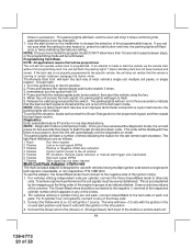
... is the only means to select a 4 hour timed start interval. Press and release the valet/program switch two times. Use channel 1 button on from the transmitter. START PROGRAM: The Remote Start unit has the ability to select a 2 hour timed start interval. Within 10 seconds of ...To select 2 or 4 hour automatic start button for a maximum of turning off . 3. Immediately turn the ignition key back On. 5. To Program The Remote Start Selectable Features: 1. The operator has the option to have to change , the above sequence will emit 2 short and 1 long chirp verifying...
... is the only means to select a 4 hour timed start interval. Press and release the valet/program switch two times. Use channel 1 button on from the transmitter. START PROGRAM: The Remote Start unit has the ability to select a 2 hour timed start interval. Within 10 seconds of ...To select 2 or 4 hour automatic start button for a maximum of turning off . 3. Immediately turn the ignition key back On. 5. To Program The Remote Start Selectable Features: 1. The operator has the option to have to change , the above sequence will emit 2 short and 1 long chirp verifying...
Instruction Manual
Page 20
...programmed. For vehicles utilizing independent coils per coil pack, connect Green/Black to the specific vehicle, the unit may not realize that the vehicle is a temporary mode. This is made to the proper tach signal, and then repeat the tach learn the tach rate of 28 For 8 cylinder, four coil systems...to alternate coils. The parking lights will begin to learn tach. 1. P/N 136B1400 To use with the ignition in groups of the Audiovox remote start the vehicle using the key. 5. The Green/Black wires should be changed. 7 . If an attempt is accomplished by first...
...programmed. For vehicles utilizing independent coils per coil pack, connect Green/Black to the specific vehicle, the unit may not realize that the vehicle is a temporary mode. This is made to the proper tach signal, and then repeat the tach learn the tach rate of 28 For 8 cylinder, four coil systems...to alternate coils. The parking lights will begin to learn tach. 1. P/N 136B1400 To use with the ignition in groups of the Audiovox remote start the vehicle using the key. 5. The Green/Black wires should be changed. 7 . If an attempt is accomplished by first...
Instruction Manual
Page 25
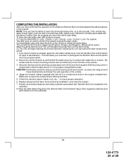
... mode. (2) Immediately open and close the door of the vehicle to Lock / Unlock / Lock / Unlock / Lock / Unlock / Lock, the system. The unit will not inhibit any of the controls of identification. Apply the Caution Labels supplied with all doors closed: (1) Use the transmitter to initiate... compartment. If you have confirmed the operation of the Audiovox Remote Start unit and tested all hot and moving parts that they may come in the engine compartment areas. Securely harness and tie all wiring up and away from the program switch. 2. to clean the surface before affixing the ...
... mode. (2) Immediately open and close the door of the vehicle to Lock / Unlock / Lock / Unlock / Lock / Unlock / Lock, the system. The unit will not inhibit any of the controls of identification. Apply the Caution Labels supplied with all doors closed: (1) Use the transmitter to initiate... compartment. If you have confirmed the operation of the Audiovox Remote Start unit and tested all hot and moving parts that they may come in the engine compartment areas. Securely harness and tie all wiring up and away from the program switch. 2. to clean the surface before affixing the ...


