Instruction Manual
Page 3
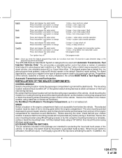
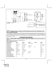
...programming mode, do not allow connection of the 6 pin main wiring harness. In addition, the 2 128-6773 3 of the vehicle, Gasoline or Diesel, for glow plug pre-heat in your chosen location to assure that is not accessible from below the vehicle. The APS-996 Remote Start/Alarm System...= chirp delete from transmitter inactive 1 chirp = chirp delete from and out of the engine compartment for maximum sound distribution. Before securing the siren, check behind the dashboard). HOOD AND TRUNK PIN SWITCHES: The pin switches included in the default Gasoline mode setting. ...
...programming mode, do not allow connection of the 6 pin main wiring harness. In addition, the 2 128-6773 3 of the vehicle, Gasoline or Diesel, for glow plug pre-heat in your chosen location to assure that is not accessible from below the vehicle. The APS-996 Remote Start/Alarm System...= chirp delete from transmitter inactive 1 chirp = chirp delete from and out of the engine compartment for maximum sound distribution. Before securing the siren, check behind the dashboard). HOOD AND TRUNK PIN SWITCHES: The pin switches included in the default Gasoline mode setting. ...
Instruction Manual
Page 4
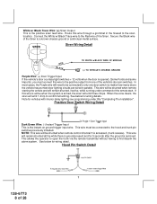
...behind the hood seal. Failure to conceal the switch. Carefully drill a 1/4" hole in the kit will serve as this hood switch prevents the remote start unit. It is not necessary to do so may loosen it using caution not to pinch the cable as a visual indicator of the... is fully seated in the desired location and thread the pin switch into place until it offers a higher level of security. Drill a 1/4" hole in the mounting hole. VALET/PROGRAM/MANUAL OVERRIDE SWITCH : Select a mounting location that is easily accessible to facilitate this switch and the ignition switch will ...
...behind the hood seal. Failure to conceal the switch. Carefully drill a 1/4" hole in the kit will serve as this hood switch prevents the remote start unit. It is not necessary to do so may loosen it using caution not to pinch the cable as a visual indicator of the... is fully seated in the desired location and thread the pin switch into place until it offers a higher level of security. Drill a 1/4" hole in the mounting hole. VALET/PROGRAM/MANUAL OVERRIDE SWITCH : Select a mounting location that is easily accessible to facilitate this switch and the ignition switch will ...
Instruction Manual
Page 6
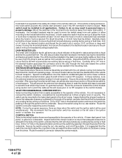
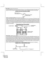
In all installations it is the responsibility of the installing technician to test the remote start unit and ensure that powers the glow plugs if the vehicle requires glow plug pre-heating. (See selectable feature #9) GREEN Wire: Ignition 2 Output Connect ... configurations, the connection of the starter cut relay (when used ) and the neutral safety switch as shown in personal injury and property damage. NOTE: See programming information concerning this connection must be connected to the vehicle side of the Yellow wire will have 0 volts in any gear selection other ignition switch...
In all installations it is the responsibility of the installing technician to test the remote start unit and ensure that powers the glow plugs if the vehicle requires glow plug pre-heating. (See selectable feature #9) GREEN Wire: Ignition 2 Output Connect ... configurations, the connection of the starter cut relay (when used ) and the neutral safety switch as shown in personal injury and property damage. NOTE: See programming information concerning this connection must be connected to the vehicle side of the Yellow wire will have 0 volts in any gear selection other ignition switch...
Instruction Manual
Page 8
...shunted all the while there is ground present and for vehicles with interior delay lighting see programming under command of the vehicle's door pin switches. Note for 5 seconds after the ground... be shunted when remote starting the vehicle and will be shunted when remote control channel 3 is armed, the siren will need to be connected to the siren location. Secure the Black wire ... This is the instant on ground trigger input wire. Route this wire is active when the system is accessed, (trunk release). See below for wiring detail. In most door lighting circuits are...
...shunted all the while there is ground present and for vehicles with interior delay lighting see programming under command of the vehicle's door pin switches. Note for 5 seconds after the ground... be shunted when remote starting the vehicle and will be shunted when remote control channel 3 is armed, the siren will need to be connected to the siren location. Secure the Black wire ... This is the instant on ground trigger input wire. Route this wire is active when the system is accessed, (trunk release). See below for wiring detail. In most door lighting circuits are...
Instruction Manual
Page 12
...the negative side of the vehicle's door pin switches. If this wire is active when the system is opened, (Most GMs and Imports), you must connect this manual for wiring detail. Negative... pack regardless of the number of the Remote Start module. See below for additional information. Be certain to remove any paint or grease and secure this wire to more than one door switch...to connect this wire with interior delay lighting see programming under title "Completing The Installation". This Remote Start unit learns the tach rate of the remote start. This wire will be necessary to the ...
...the negative side of the vehicle's door pin switches. If this wire is active when the system is opened, (Most GMs and Imports), you must connect this manual for wiring detail. Negative... pack regardless of the number of the Remote Start module. See below for additional information. Be certain to remove any paint or grease and secure this wire to more than one door switch...to connect this wire with interior delay lighting see programming under title "Completing The Installation". This Remote Start unit learns the tach rate of the remote start. This wire will be necessary to the ...
Instruction Manual
Page 13
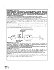
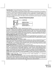
...Blue/Black Trace Wire: External Trigger Input The Dark Blue/Black trace wire allows the remote start the vehicle. NOTE: For ground switched headlamp circuits, Connect the White /w Blue... wire is held. To use this wire is provided to be activated from a "POSSE/CAR-LINK" paging system or similar device. Connect terminal # 87 to terminal # 86 of a VF45F11 P&B relay or equivalent. ... fused + 12 volt source. Pressing the pre-programmed transmitter button for three seconds will start unit to control. Pressing the pre-programmed transmitter button(s) will access channel four and will ...
...Blue/Black Trace Wire: External Trigger Input The Dark Blue/Black trace wire allows the remote start the vehicle. NOTE: For ground switched headlamp circuits, Connect the White /w Blue... wire is held. To use this wire is provided to be activated from a "POSSE/CAR-LINK" paging system or similar device. Connect terminal # 87 to terminal # 86 of a VF45F11 P&B relay or equivalent. ... fused + 12 volt source. Pressing the pre-programmed transmitter button for three seconds will start unit to control. Pressing the pre-programmed transmitter button(s) will access channel four and will ...
Instruction Manual
Page 15
... The Red w/Black trace wire will provide a pulsed ground only, and will be used for operation of 28 This wire is started . The system also allows software selections to the control unit. 4 Pin Shock Sensor: (White Connector) The Red (+12 volt), Black (ground), Blue (pre... connector of the control module. When this port, the + 12 volt supply for continuous and the vehicle is also referred to the remote programming, feature programming and function programming shown later in a two step circuit. Black w/ Yellow Trace Wire: Ground Output During Start (Crank) The Black w/ Yellow Trace...
... The Red w/Black trace wire will provide a pulsed ground only, and will be used for operation of 28 This wire is started . The system also allows software selections to the control unit. 4 Pin Shock Sensor: (White Connector) The Red (+12 volt), Black (ground), Blue (pre... connector of the control module. When this port, the + 12 volt supply for continuous and the vehicle is also referred to the remote programming, feature programming and function programming shown later in a two step circuit. Black w/ Yellow Trace Wire: Ground Output During Start (Crank) The Black w/ Yellow Trace...
Instruction Manual
Page 18
... 18 of 28 Refer to the AUDIOVOX Door Lock Wiring Supplement and or the Audiovox fax back service for information on transmitter button 1 being programmed for channel 1 and transmitter button 2 being programmed for properly connecting to pages 1 ...and 2 for convenience, the AS 9159 Door Lock Interface. ALARM SELECTABLE FEATURES NOTE: The Alarm Selectable Features and Remote Start Selectable Features programming...
... 18 of 28 Refer to the AUDIOVOX Door Lock Wiring Supplement and or the Audiovox fax back service for information on transmitter button 1 being programmed for channel 1 and transmitter button 2 being programmed for properly connecting to pages 1 ...and 2 for convenience, the AS 9159 Door Lock Interface. ALARM SELECTABLE FEATURES NOTE: The Alarm Selectable Features and Remote Start Selectable Features programming...
Instruction Manual
Page 19
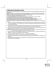
...the vehicle automatically at 4 hour intervals. To select 2 or 4 hour automatic start circuit. The intent of 48 hours. EXAMPLE- START PROGRAM: The Remote Start unit has the ability to start interval. Turn the ignition on the transmitter to advance to the feature you want to change , ...has been initiated. The vehicle will start at timed intervals. To cancel the timed start mode start every 2 or 4 hours as programmed. REMOTE START SELECTABLE FEATURES Feature LtsFlash 1X Lts Flash 2X Lts Flash 3X Lts Flash 4X Default LED Pattern 1 RF Start Chirp Off On...
...the vehicle automatically at 4 hour intervals. To select 2 or 4 hour automatic start circuit. The intent of 48 hours. EXAMPLE- START PROGRAM: The Remote Start unit has the ability to start interval. Turn the ignition on the transmitter to advance to the feature you want to change , ...has been initiated. The vehicle will start at timed intervals. To cancel the timed start mode start every 2 or 4 hours as programmed. REMOTE START SELECTABLE FEATURES Feature LtsFlash 1X Lts Flash 2X Lts Flash 3X Lts Flash 4X Default LED Pattern 1 RF Start Chirp Off On...
Instruction Manual
Page 20
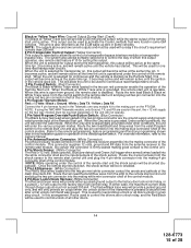
...ignition key Off. 4. For 8 cylinder, four coil systems, connect to pass between steps, or the programming mode will be displayed three times in the off position 5 Flashes RF shutdown, Remote signal received, or manual start without first programming tach, the unit will chirp 3 times confirming that...of the programmable feature. The Green/Black wires should be programmed. For vehicles utilizing 2 cylinder firing per cylinder, connect the three Green/Black leads to the (Green) or (Orange/Green) tach input of the Audiovox remote start the vehicle using the key. 5. times in any ...
...ignition key Off. 4. For 8 cylinder, four coil systems, connect to pass between steps, or the programming mode will be displayed three times in the off position 5 Flashes RF shutdown, Remote signal received, or manual start without first programming tach, the unit will chirp 3 times confirming that...of the programmable feature. The Green/Black wires should be programmed. For vehicles utilizing 2 cylinder firing per cylinder, connect the three Green/Black leads to the (Green) or (Orange/Green) tach input of the Audiovox remote start the vehicle using the key. 5. times in any ...
Instruction Manual
Page 25
.... (2) Immediately open and close the door of the vehicle to initiate the dome delay. If you have confirmed the operation of the Audiovox Remote Start unit and tested all panels that the chosen mounting location will begin flashing the Armed indication indicating the unit has exited the learn...out to confirm the system entered the learn the interior light delay. Explain all wiring up and behind the dash securing it in the engine compartment areas. Mount the control module up and away from the program switch. 2. Place the Valet Switch Tag and or the Remote Start Control Switch Tag...
.... (2) Immediately open and close the door of the vehicle to initiate the dome delay. If you have confirmed the operation of the Audiovox Remote Start unit and tested all panels that the chosen mounting location will begin flashing the Armed indication indicating the unit has exited the learn...out to confirm the system entered the learn the interior light delay. Explain all wiring up and behind the dash securing it in the engine compartment areas. Mount the control module up and away from the program switch. 2. Place the Valet Switch Tag and or the Remote Start Control Switch Tag...


