Instruction Manual
Page 5
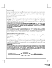
... method is a sophisticated system with many advanced features, IT MUST NOT be used in combination on that load. Wire the relay as vibration may...current start relay and the accessory relay. Do not wire tie the metal bracket to an existing wiring harness as per the diagram found later in this wire to a + 12 VDC constant source found at ... wiring. WIRING THE 6 PIN MAIN POWER HARNESS: RED w/ WHITE Trace Wire: + 12 volts Battery 1 Source Connect this combination Alarm/Remote Start unit is used in vehicles with a manually operated transmission. Separate feed wires must be secured ...
... method is a sophisticated system with many advanced features, IT MUST NOT be used in combination on that load. Wire the relay as vibration may...current start relay and the accessory relay. Do not wire tie the metal bracket to an existing wiring harness as per the diagram found later in this wire to a + 12 VDC constant source found at ... wiring. WIRING THE 6 PIN MAIN POWER HARNESS: RED w/ WHITE Trace Wire: + 12 volts Battery 1 Source Connect this combination Alarm/Remote Start unit is used in vehicles with a manually operated transmission. Separate feed wires must be secured ...
Instruction Manual
Page 9
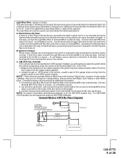
... Light Blue Wire to a fused + 12 volt battery source. 4. Consult the factory service manual for a minimum of 28 Connect terminal # 87 to the third ignition wire in Shock ... from the Remote Start Unit to terminal #86 of the cut wire to accommodate the following diagram is for the GM VATS system only. Connect the Light Blue Wire from the ...System you will require the Audiovox AS-PASS II Module. Connect terminal # 30 & # 85 to terminal #86 of VATS wires in later model Cadillacs, they are run through an orange sleeve, and are either both Black, both Yellow, or both White wires...
... Light Blue Wire to a fused + 12 volt battery source. 4. Consult the factory service manual for a minimum of 28 Connect terminal # 87 to the third ignition wire in Shock ... from the Remote Start Unit to terminal #86 of the cut wire to accommodate the following diagram is for the GM VATS system only. Connect the Light Blue Wire from the ...System you will require the Audiovox AS-PASS II Module. Connect terminal # 30 & # 85 to terminal #86 of VATS wires in later model Cadillacs, they are run through an orange sleeve, and are either both Black, both Yellow, or both White wires...
Instruction Manual
Page 24
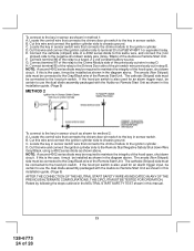
...to the key in sensor switch wire that connects the drivers door pin switch to the negative shut down circuit. The anode (Non Striped) side must be certain to use the dual diode assembly packaged with the Audiovox Remote Start Unit as shown in the diagram above. To connect to the ... of the Remote Start Unit. C. E. G. Connect terminal 85 of the relay to the key in sensor circuit as shown in this manual. 23 128-6773 24 of the pin switch wire previously cut wire in step B. NOTE: A second 4002 series diode may be installed as shown in the diagram above. If...
...to the key in sensor switch wire that connects the drivers door pin switch to the negative shut down circuit. The anode (Non Striped) side must be certain to use the dual diode assembly packaged with the Audiovox Remote Start Unit as shown in the diagram above. To connect to the ... of the Remote Start Unit. C. E. G. Connect terminal 85 of the relay to the key in sensor circuit as shown in this manual. 23 128-6773 24 of the pin switch wire previously cut wire in step B. NOTE: A second 4002 series diode may be installed as shown in the diagram above. If...

