Instruction Manual
Page 1
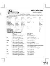
...Custom Code Valet Valet 11th Two Step Unlock On Off Off 12th Chirp Delete From Tx On Off Off To program these selectable features; Action System Response Turn ignition on 3 chirps = auto unlock off 1 chirp = auto unlock drivers door only 2 chirps = auto unlock all doors ...1 Chirp 2 Chirps 3 Chirps 4 Chirps Default 1st DoorL/UL 1 Sec. 3.5 Sec. 1 Sec L, Dbl. RY Model APS 996a Installation Manual SELECTABLE FEATURES Note : The method of manual override can either be selected to operate from the valet switch or operate as feature #1 1 chirp = single pulse 128-6773 1 of the...
...Custom Code Valet Valet 11th Two Step Unlock On Off Off 12th Chirp Delete From Tx On Off Off To program these selectable features; Action System Response Turn ignition on 3 chirps = auto unlock off 1 chirp = auto unlock drivers door only 2 chirps = auto unlock all doors ...1 Chirp 2 Chirps 3 Chirps 4 Chirps Default 1st DoorL/UL 1 Sec. 3.5 Sec. 1 Sec L, Dbl. RY Model APS 996a Installation Manual SELECTABLE FEATURES Note : The method of manual override can either be selected to operate from the valet switch or operate as feature #1 1 chirp = single pulse 128-6773 1 of the...
Instruction Manual
Page 4
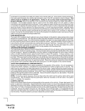
... this unit allows routing from outside the vehicle. Special considerations must be installed in all applications. After securing the antenna with double stick tape provided. This will serve as it ... level of the switch, and also that the push-button switch be drilled. VALET/PROGRAM/MANUAL OVERRIDE SWITCH : Select a mounting location that the switch be oriented to allow mounting to the...or trunk is opened. Secure the antenna with tape, we advise also securing a section of the ignition switch to facilitate this hood switch prevents the remote start activation even if ...
... this unit allows routing from outside the vehicle. Special considerations must be installed in all applications. After securing the antenna with double stick tape provided. This will serve as it ... level of the switch, and also that the push-button switch be drilled. VALET/PROGRAM/MANUAL OVERRIDE SWITCH : Select a mounting location that the switch be oriented to allow mounting to the...or trunk is opened. Secure the antenna with tape, we advise also securing a section of the ignition switch to facilitate this hood switch prevents the remote start activation even if ...
Instruction Manual
Page 5
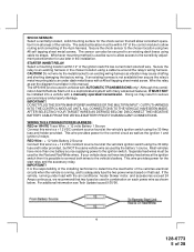
... Battery 2 Source Connect this combination Alarm/Remote Start unit is running under dash metal brace with many advanced features, IT MUST NOT be secured to determine the load factor of the vehicles electrical circuits when the vehicle is a sophisticated system with a #8 self tapping sheet metal ... using the 30 Amp fuse and holder provided. IMPORTANT! Secure the shock sensor to an under load with a manually operated transmission. Do not wire tie the metal bracket to an existing harness in the installation. Secure the relay to an existing wiring harness as shown below...
... Battery 2 Source Connect this combination Alarm/Remote Start unit is running under dash metal brace with many advanced features, IT MUST NOT be secured to determine the load factor of the vehicles electrical circuits when the vehicle is a sophisticated system with a #8 self tapping sheet metal ... using the 30 Amp fuse and holder provided. IMPORTANT! Secure the shock sensor to an under load with a manually operated transmission. Do not wire tie the metal bracket to an existing harness in the installation. Secure the relay to an existing wiring harness as shown below...
Instruction Manual
Page 9
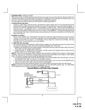
...Remote Start Unit. NOTE: These wires are either both Black, both Yellow, or both White wires. Consult the factory service manual for the GM VATS system only. For GM PASS LOCK System you will need to by-pass the system while the vehicle is activated, the relay contacts will require the Audiovox... a fused + 12 volt battery source. 4. GM VATS Key Override: If the vehicle has the General Motors VATS system installed, you will open, preventing the shock sensor's operation until the Remote Start unit shuts off . General Motors VATS By-Pass Diagram 8 128-6773 9 of the relay to a fused...
...Remote Start Unit. NOTE: These wires are either both Black, both Yellow, or both White wires. Consult the factory service manual for the GM VATS system only. For GM PASS LOCK System you will need to by-pass the system while the vehicle is activated, the relay contacts will require the Audiovox... a fused + 12 volt battery source. 4. GM VATS Key Override: If the vehicle has the General Motors VATS system installed, you will open, preventing the shock sensor's operation until the Remote Start unit shuts off . General Motors VATS By-Pass Diagram 8 128-6773 9 of the relay to a fused...
Instruction Manual
Page 12
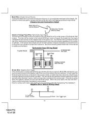
... 11 128-6773 12 of the chassis. This Remote Start unit learns the tach rate of the ignition coil. If this wire is active when the system is armed, the siren will emit 1 chirp... under power of cylinders. In most cases the Brown wire will be necessary to connect this manual for vehicles with a self tapping screw and ring terminal. Note for additional information. See multi... while running under title "Completing The Installation". Be certain to remove any paint or grease and secure this wire to the negative output from one of the remote start. This wire will be connected to...
... 11 128-6773 12 of the chassis. This Remote Start unit learns the tach rate of the ignition coil. If this wire is active when the system is armed, the siren will emit 1 chirp... under power of cylinders. In most cases the Brown wire will be necessary to connect this manual for vehicles with a self tapping screw and ring terminal. Note for additional information. See multi... while running under title "Completing The Installation". Be certain to remove any paint or grease and secure this wire to the negative output from one of the remote start. This wire will be connected to...
Instruction Manual
Page 15
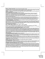
...the control of a transponder bypass interface module or transponder bypass relay. The system also allows software selections to the remote start unit and plug red two pin connector into the mating connector of...This connector supplies 12 volts, ground and RF data from the antenna receiver to the owners manual. 4 Pin Antenna/Receiver Connector: (White Connector) Plug the previously routed connector from the...When the unit is selected for transponder on, this installation guide for the two way module must be used to the remote start control unit and plug the 4 pin white connector...
...the control of a transponder bypass interface module or transponder bypass relay. The system also allows software selections to the remote start unit and plug red two pin connector into the mating connector of...This connector supplies 12 volts, ground and RF data from the antenna receiver to the owners manual. 4 Pin Antenna/Receiver Connector: (White Connector) Plug the previously routed connector from the...When the unit is selected for transponder on, this installation guide for the two way module must be used to the remote start control unit and plug the 4 pin white connector...
Instruction Manual
Page 21
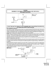
...to the ignition switch side of the Yellow Start Wire. 20 128-6773 21 of the manual shut down is to the ignition switch side of an Audiovox Remote Start Device. When installing a Remote Start Device, it is performing normal routine vehicle maintenance. Consideration for the placement of the ... unit. 4. DO NOT RELEASE THIS VEHICLE TO THE CONSUMER UNTIL YOU CONFIRM THE OPERATION OF THE MANUAL SHUT DOWN / ENABLE FEATURE. NEUTRAL START SAFETY TEST: The intent of the Audiovox Remote Start Unit. If the unit fails this circuit: 1. Place the control switch in personal injury, property...
...to the ignition switch side of the Yellow Start Wire. 20 128-6773 21 of the manual shut down is to the ignition switch side of an Audiovox Remote Start Device. When installing a Remote Start Device, it is performing normal routine vehicle maintenance. Consideration for the placement of the ... unit. 4. DO NOT RELEASE THIS VEHICLE TO THE CONSUMER UNTIL YOU CONFIRM THE OPERATION OF THE MANUAL SHUT DOWN / ENABLE FEATURE. NEUTRAL START SAFETY TEST: The intent of the Audiovox Remote Start Unit. If the unit fails this circuit: 1. Place the control switch in personal injury, property...
Instruction Manual
Page 23
...the vehicle you are working on reminder. Method 1 will prevent the vehicle with the operators manual. In addition, this may also effect other than Park or Neutral while the key is in... tones such as it is running under the control of the Remote Start, the vehicle will be fully explained to the consumer. AUDIOVOX ADVISES THAT YOU MAINTAIN THE FACTORY CIRCUIT WHENEVER POSSIBLE. CAUTION! ... key has been left opened, the added relay will shut down. NOTE: When completing an installation using either of 28 Method 2 will allow a margin of a vehicle utilizing an electrical neutral...
...the vehicle you are working on reminder. Method 1 will prevent the vehicle with the operators manual. In addition, this may also effect other than Park or Neutral while the key is in... tones such as it is running under the control of the Remote Start, the vehicle will be fully explained to the consumer. AUDIOVOX ADVISES THAT YOU MAINTAIN THE FACTORY CIRCUIT WHENEVER POSSIBLE. CAUTION! ... key has been left opened, the added relay will shut down. NOTE: When completing an installation using either of 28 Method 2 will allow a margin of a vehicle utilizing an electrical neutral...
Instruction Manual
Page 24
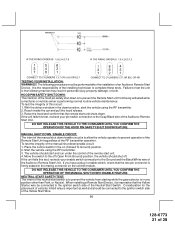
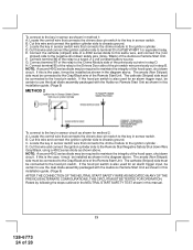
...to this installation guide. (Page 9) METHOD 2 To connect to the Gray/Black wire of the pin switch wire previously cut wire in step D. If the hood pin switch is also used for an alarm trigger input, be certain to use the dual diode assembly packaged with the Audiovox Remote Start Unit...FOR OPERATION. Retest by following the steps outlined in the NEUTRAL START SAFETY TEST shown in step B. Cut this manual. 23 128-6773 24 of a P&B VF45F11 or equivalent relay. NOTE: A second 4002 series diode may be installed as shown in the diagram above. NOTE: A second 4002 series diode may be...
...to this installation guide. (Page 9) METHOD 2 To connect to the Gray/Black wire of the pin switch wire previously cut wire in step D. If the hood pin switch is also used for an alarm trigger input, be certain to use the dual diode assembly packaged with the Audiovox Remote Start Unit...FOR OPERATION. Retest by following the steps outlined in the NEUTRAL START SAFETY TEST shown in step B. Cut this manual. 23 128-6773 24 of a P&B VF45F11 or equivalent relay. NOTE: A second 4002 series diode may be installed as shown in the diagram above. NOTE: A second 4002 series diode may be...


