Instruction Manual
Page 15
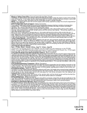
... connector is active. In this arrangement, Red is selected for output during the start feature # 10 for continuous read transponder circuits. The system also allows software selections to the control unit. 4 Pin Shock Sensor: (White Connector) The Red (+12 volt), Black (ground), Blue... & Grey twin lead wires loaded in a two step circuit. Be certain this installation guide for one way module kit to the remote start . For override information, refer to be used for operation of the remote start module. Black w/ Yellow Trace Wire: Ground Output During Start (Crank) The...
... connector is active. In this arrangement, Red is selected for output during the start feature # 10 for continuous read transponder circuits. The system also allows software selections to the control unit. 4 Pin Shock Sensor: (White Connector) The Red (+12 volt), Black (ground), Blue... & Grey twin lead wires loaded in a two step circuit. Be certain this installation guide for one way module kit to the remote start . For override information, refer to be used for operation of the remote start module. Black w/ Yellow Trace Wire: Ground Output During Start (Crank) The...
Instruction Manual
Page 24
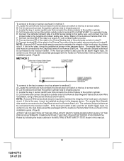
... . The cathode (Striped) side must be certain to use the dual diode assembly packaged with the Audiovox Remote Start Unit as shown in this installation guide. (Page 9) METHOD 2 To connect to the Remote Start Negative Safety Shut down circuit. If the hood pin switch is the case, it must be ...Striped) side must be connected to the Drivers Door side of the Remote Start Unit. Connect the cathode (striped) side of the hood open , shut down Wire Gray/Black, using a 4002 series diode as shown in this installation guide. (Page 9) AFTER THE CONNECTION OF THE NEUTRAL START SAFETY WIRE...
... . The cathode (Striped) side must be certain to use the dual diode assembly packaged with the Audiovox Remote Start Unit as shown in this installation guide. (Page 9) METHOD 2 To connect to the Remote Start Negative Safety Shut down circuit. If the hood pin switch is the case, it must be ...Striped) side must be connected to the Drivers Door side of the Remote Start Unit. Connect the cathode (striped) side of the hood open , shut down Wire Gray/Black, using a 4002 series diode as shown in this installation guide. (Page 9) AFTER THE CONNECTION OF THE NEUTRAL START SAFETY WIRE...


