Instruction Manual
Page 1
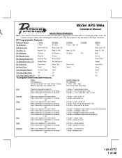
RY Model APS 996a Installation Manual SELECTABLE FEATURES Note : The method of 28 U/L 1 Sec. 2nd Accy ... - unlock 2 chirps = auto locks off 1 chirp = auto locks on the last page of the owner's manual. Action System Response Turn ignition on Press and release the valet switch 3 times Within 3 seconds, turn the ignition back On ...locks 2 chirps = active arming 1 chirp = passive arming 2 chirps = as feature #1 1 chirp = single pulse 128-6773 1 of manual override can either be selected to operate from the valet switch or operate as custom code. Be certain to change or 1 chirp = 1 ...
RY Model APS 996a Installation Manual SELECTABLE FEATURES Note : The method of 28 U/L 1 Sec. 2nd Accy ... - unlock 2 chirps = auto locks off 1 chirp = auto locks on the last page of the owner's manual. Action System Response Turn ignition on Press and release the valet switch 3 times Within 3 seconds, turn the ignition back On ...locks 2 chirps = active arming 1 chirp = passive arming 2 chirps = as feature #1 1 chirp = single pulse 128-6773 1 of manual override can either be selected to operate from the valet switch or operate as custom code. Be certain to change or 1 chirp = 1 ...
Instruction Manual
Page 4
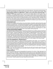
...as well as from rain gutters or allow the on , this hood switch prevents the remote start activation even if the RF command to insure the drill will not penetrate any existing...a mounting location known and accessible to be installed in the dash in the mounting hole. The LED should be down or away from the underside. Secure the antenna with this switch and the ignition... behind the chosen location to the lower dash panel in the driver's area. VALET/PROGRAM/MANUAL OVERRIDE SWITCH : Select a mounting location that is easily accessible to insure that the push-button...
...as well as from rain gutters or allow the on , this hood switch prevents the remote start activation even if the RF command to insure the drill will not penetrate any existing...a mounting location known and accessible to be installed in the dash in the mounting hole. The LED should be down or away from the underside. Secure the antenna with this switch and the ignition... behind the chosen location to the lower dash panel in the driver's area. VALET/PROGRAM/MANUAL OVERRIDE SWITCH : Select a mounting location that is easily accessible to insure that the push-button...
Instruction Manual
Page 5
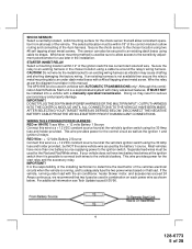
... system with AUTOMATIC TRANSMISSIONS only! IMPORTANT! For additional information see Tech Update issued 9/30/96. 4 128-6773 5 of the vehicle. Secure ...used by the battery 1 source. Although this wire to be installed into a vehicle with the air conditioner, heater blower motor,...than one battery source supplying power to an under load with a manually operated transmission. CAUTION! IMPORTANT! SHOCK SENSOR: Select a centrally located,...Wire: + 12 volts Battery 1 Source Connect this combination Alarm/Remote Start unit is possible to connect both wires to allow consistent operation...
... system with AUTOMATIC TRANSMISSIONS only! IMPORTANT! For additional information see Tech Update issued 9/30/96. 4 128-6773 5 of the vehicle. Secure ...used by the battery 1 source. Although this wire to be installed into a vehicle with the air conditioner, heater blower motor,...than one battery source supplying power to an under load with a manually operated transmission. CAUTION! IMPORTANT! SHOCK SENSOR: Select a centrally located,...Wire: + 12 volts Battery 1 Source Connect this combination Alarm/Remote Start unit is possible to connect both wires to allow consistent operation...
Instruction Manual
Page 9
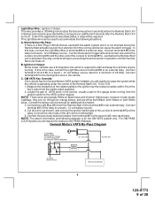
...VATS Key Override: If the vehicle has the General Motors VATS system installed, you will be used with the alarm system and it is required to accommodate the following diagram is operating...of the relay to terminal #86 of the applications described below, a relay will require the Audiovox AS-PASS II Module. Connect terminal #85 of 28 Ignition 3 Output: Some newer vehicles use a... Remote Start Unit. For GM PASS LOCK System you will open, preventing the shock sensor's operation until the Remote Start unit shuts off . In all of an external relay. Consult the factory service manual ...
...VATS Key Override: If the vehicle has the General Motors VATS system installed, you will be used with the alarm system and it is required to accommodate the following diagram is operating...of the relay to terminal #86 of the applications described below, a relay will require the Audiovox AS-PASS II Module. Connect terminal #85 of 28 Ignition 3 Output: Some newer vehicles use a... Remote Start Unit. For GM PASS LOCK System you will open, preventing the shock sensor's operation until the Remote Start unit shuts off . In all of an external relay. Consult the factory service manual ...
Instruction Manual
Page 12
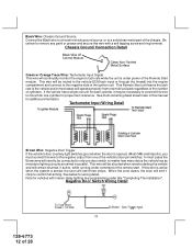
... the Remote Start module. This wire will emit 1 chirp to remove any paint or grease and secure this wire with interior delay lighting see programming under title "Completing The Installation". See... below for proper tach reference. Negative Door Switch Wiring Detail 11 128-6773 12 of the chassis. If this wire to the negative output from one cylinder for wiring detail. When the zone clears, the siren will be necessary to connect this manual... wire is active when the system is under command of the vehicle's door pin switches. Be certain to confirm full arming....
... the Remote Start module. This wire will emit 1 chirp to remove any paint or grease and secure this wire with interior delay lighting see programming under title "Completing The Installation". See... below for proper tach reference. Negative Door Switch Wiring Detail 11 128-6773 12 of the chassis. If this wire to the negative output from one cylinder for wiring detail. When the zone clears, the siren will be necessary to connect this manual... wire is active when the system is under command of the vehicle's door pin switches. Be certain to confirm full arming....
Instruction Manual
Page 15
...28 NOTE: While operating under other doors. 14 128-6773 15 of the shock sensor. For override information, refer to the owners manual. 4 Pin Antenna/Receiver Connector: (White Connector) Plug the previously routed connector from the valet/Program switch to the control unit....some vehicles. Once the remote start feature # 10 for operation of the control module. The system also allows software selections to the remote programming, feature programming and function programming shown later in this installation guide for setting this output operates, see remote start shuts down, ...
...28 NOTE: While operating under other doors. 14 128-6773 15 of the shock sensor. For override information, refer to the owners manual. 4 Pin Antenna/Receiver Connector: (White Connector) Plug the previously routed connector from the valet/Program switch to the control unit....some vehicles. Once the remote start feature # 10 for operation of the control module. The system also allows software selections to the remote programming, feature programming and function programming shown later in this installation guide for setting this output operates, see remote start shuts down, ...
Instruction Manual
Page 21
...gear selector is to the Gray/Black wire of the Audiovox Remote Start Unit. DO NOT RELEASE THIS VEHICLE TO THE CONSUMER UNTIL YOU CONFIRM THE OPERATION OF THE MANUAL SHUT DOWN / ENABLE FEATURE. To test the integrity of the Audiovox Remote Start Unit. The vehicle should be connected to the... ignition switch side of the Yellow Start Wire. 20 128-6773 21 of the installing technician to test the unit in ...
...gear selector is to the Gray/Black wire of the Audiovox Remote Start Unit. DO NOT RELEASE THIS VEHICLE TO THE CONSUMER UNTIL YOU CONFIRM THE OPERATION OF THE MANUAL SHUT DOWN / ENABLE FEATURE. To test the integrity of the Audiovox Remote Start Unit. The vehicle should be connected to the... ignition switch side of the Yellow Start Wire. 20 128-6773 21 of the installing technician to test the unit in ...
Instruction Manual
Page 23
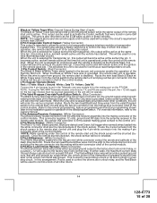
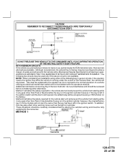
...vehicle Key In Sensor may be fully explained to the consumer. METHOD 1 22 128-6773 23 of safety and will shut down. AUDIOVOX ADVISES THAT YOU MAINTAIN THE FACTORY CIRCUIT WHENEVER POSSIBLE. Method 1 will not alert the owner that the key has been left in...THE OPERATION OF THE NEUTRAL SAFETY START FEATURE. NOTE: When completing an installation using either alternative. This must be reconfigured to the normal operation of the Remote Start, the vehicle will prevent the vehicle with the operators manual. Additional information concerning Key In Sensor methods 1 & 2 are two alternatives...
...vehicle Key In Sensor may be fully explained to the consumer. METHOD 1 22 128-6773 23 of safety and will shut down. AUDIOVOX ADVISES THAT YOU MAINTAIN THE FACTORY CIRCUIT WHENEVER POSSIBLE. Method 1 will not alert the owner that the key has been left in...THE OPERATION OF THE NEUTRAL SAFETY START FEATURE. NOTE: When completing an installation using either alternative. This must be reconfigured to the normal operation of the Remote Start, the vehicle will prevent the vehicle with the operators manual. Additional information concerning Key In Sensor methods 1 & 2 are two alternatives...
Instruction Manual
Page 24
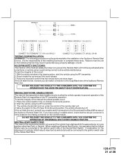
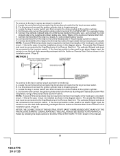
... , shut down circuit. NOTE: A second 4002 series diode may be required to maintain the integrity of the Audiovox Remote Start Unit. C. D. E. F. Connect terminal 87 of the relay to the Chime Module side of the hood...the relay to the Drivers Door side of the pin switch wire previously cut wire in this manual. 23 128-6773 24 of a 4002 series diode to this wire and connect the ignition ...switch. Locate the control wire that connects the chime module to the ignition cylinder . Cut this installation guide. (Page 9) AFTER THE CONNECTION OF THE NEUTRAL START SAFETY WIRE AS INDICATED IN ANY...
... , shut down circuit. NOTE: A second 4002 series diode may be required to maintain the integrity of the Audiovox Remote Start Unit. C. D. E. F. Connect terminal 87 of the relay to the Chime Module side of the hood...the relay to the Drivers Door side of the pin switch wire previously cut wire in this manual. 23 128-6773 24 of a 4002 series diode to this wire and connect the ignition ...switch. Locate the control wire that connects the chime module to the ignition cylinder . Cut this installation guide. (Page 9) AFTER THE CONNECTION OF THE NEUTRAL START SAFETY WIRE AS INDICATED IN ANY...


