Installation Manual
Page 1
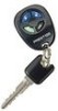
...Auto Lock On Auto Lock Off 3rd Accy. NOTE: Keyless Entry Models with no selection will Flash the Parking Lights instead of the owner's manual. RF Programmable Feature Bank 1 Is For Transmitter Programming See Transmitter Programming Guide. Be certain to place a check mark indicating the method used in...can be set features using the RF programmer, enter the program mode as explained below, or with the programmer. Model APS-687 Installation Manual The selectable features can either be selected to operate from the valet switch or operate as custom code. Note : The method of ...
...Auto Lock On Auto Lock Off 3rd Accy. NOTE: Keyless Entry Models with no selection will Flash the Parking Lights instead of the owner's manual. RF Programmable Feature Bank 1 Is For Transmitter Programming See Transmitter Programming Guide. Be certain to place a check mark indicating the method used in...can be set features using the RF programmer, enter the program mode as explained below, or with the programmer. Model APS-687 Installation Manual The selectable features can either be selected to operate from the valet switch or operate as custom code. Note : The method of ...
Installation Manual
Page 5
...also securing a section of the vehicle. Inspect behind the dashboard). Special considerations must be drilled. After securing the antenna with a manually operated transmission. MUST HAVE a Tach Signal Input, and an Automatic Transmission. NOTE: Do Not Mount The Module In The Engine ...this combination Keyless Entry/Remote Start unit is a sophisticated system with proper operation of the switch, and also that the drill will not penetrate any existing factory wiring or fluid lines. This system is to be installed in all applications. INSTALLATION OF THE MAJOR COMPONENTS...
...also securing a section of the vehicle. Inspect behind the dashboard). Special considerations must be drilled. After securing the antenna with a manually operated transmission. MUST HAVE a Tach Signal Input, and an Automatic Transmission. NOTE: Do Not Mount The Module In The Engine ...this combination Keyless Entry/Remote Start unit is a sophisticated system with proper operation of the switch, and also that the drill will not penetrate any existing factory wiring or fluid lines. This system is to be installed in all applications. INSTALLATION OF THE MAJOR COMPONENTS...
Installation Manual
Page 11
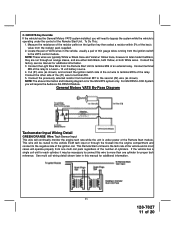
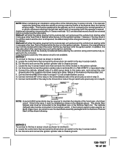
... of the Remote Start module. Cut (#1) wire (as shown). This wire will operate properly from terminal #87 to the second (#2) wire (as shown), and connect the ignition switch side of the ignition coil. C. See multi coil wiring detail shown later in most cases will be necessary to connect this manual for additional information...
... of the Remote Start module. Cut (#1) wire (as shown). This wire will operate properly from terminal #87 to the second (#2) wire (as shown), and connect the ignition switch side of the ignition coil. C. See multi coil wiring detail shown later in most cases will be necessary to connect this manual for additional information...
Installation Manual
Page 12
... the glow plug circuit gets energized, (+ 12 volts), when the glow plug circuit of the remote start unit shuts down. This will be active at the same time ign. 3 becomes active and will be installed as close to the high current wire as how to the Glow Plug Bulb wire in the ... outputs and the time in which effectively grounds the wait to a diesel vehicles glow plug wire. When the unit is manually terminated. Black w Blue Trace Wire: Pulsed Ground Output Before Start The Black w/ Blue Trace wire will allow you are low current outputs and must go to + 12 then to ground...
... the glow plug circuit gets energized, (+ 12 volts), when the glow plug circuit of the remote start unit shuts down. This will be active at the same time ign. 3 becomes active and will be installed as close to the high current wire as how to the Glow Plug Bulb wire in the ... outputs and the time in which effectively grounds the wait to a diesel vehicles glow plug wire. When the unit is manually terminated. Black w Blue Trace Wire: Pulsed Ground Output Before Start The Black w/ Blue Trace wire will allow you are low current outputs and must go to + 12 then to ground...
Installation Manual
Page 16
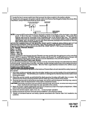
... the Remote Start unit from starting while the gear selector is fully functional one long flashes and continues this pattern until returned to test the unit in the service mode and will not start the engine using the RF transmitter. 2. Reach inside the car and ...Keeping the brake pedal depressed, activate the RF transmitter in personal injury, property damage, or both. MANUAL SHUT DOWN / ENABLE CIRCUIT: The intent of the Audiovox Remote Start Unit. Set the vehicle parking brake. 2. TESTING YOUR INSTALLATION: W A R N I N G ! ! The following manner may result in an attempt ...
... the Remote Start unit from starting while the gear selector is fully functional one long flashes and continues this pattern until returned to test the unit in the service mode and will not start the engine using the RF transmitter. 2. Reach inside the car and ...Keeping the brake pedal depressed, activate the RF transmitter in personal injury, property damage, or both. MANUAL SHUT DOWN / ENABLE CIRCUIT: The intent of the Audiovox Remote Start Unit. Set the vehicle parking brake. 2. TESTING YOUR INSTALLATION: W A R N I N G ! ! The following manner may result in an attempt ...
Installation Manual
Page 18
...use the dual diode assembly packaged with the operator's manual. METHOD 1 To connect to the key in method 1: A. Locate the control wire that connects the drivers door pin switch to the Chime Module side of 20 Connect terminal #86 of the Audiovox Remote Start Unit. H. METHOD 2 To connect to a fused ...the key is running under the control of the Remote Start, the vehicle will not alert the owner that connects the chime module to the Drivers Door side of the hood open, shut down circuit. NOTE: When completing an installation using either alternative. Locate the key in sensor ...
...use the dual diode assembly packaged with the operator's manual. METHOD 1 To connect to the key in method 1: A. Locate the control wire that connects the drivers door pin switch to the Chime Module side of 20 Connect terminal #86 of the Audiovox Remote Start Unit. H. METHOD 2 To connect to a fused ...the key is running under the control of the Remote Start, the vehicle will not alert the owner that connects the chime module to the Drivers Door side of the hood open, shut down circuit. NOTE: When completing an installation using either alternative. Locate the key in sensor ...
Installation Manual
Page 19
...the two way module must be connected to the vehicle as shown in the diagram above . COMPLETING THE INSTALLATION: After you have confirmed the operation of the Audiovox Remote Start unit and tested all panels that the chosen mounting location will not inhibit any of the controls of ... . Using the Blue 4 pin blue, red, black, & white harness and connect to the Alarm/Remote Start's control module. This will not operate. 4 Pin Upgrade Data Bus/Flash Logic Module: If you are used on this manual. 4 Pin Upgrade Telematic Module: Red = + 5 Volts Black = Ground White = Data TX Yellow...
...the two way module must be connected to the vehicle as shown in the diagram above . COMPLETING THE INSTALLATION: After you have confirmed the operation of the Audiovox Remote Start unit and tested all panels that the chosen mounting location will not inhibit any of the controls of ... . Using the Blue 4 pin blue, red, black, & white harness and connect to the Alarm/Remote Start's control module. This will not operate. 4 Pin Upgrade Data Bus/Flash Logic Module: If you are used on this manual. 4 Pin Upgrade Telematic Module: Red = + 5 Volts Black = Ground White = Data TX Yellow...


