
Motherboard DIY Troubleshooting Guide
Page 38
PWR Ground Reset Ground P4P800S Reset SW ® IDE_LED ATX Power Switch* * Requires an ATX power supply. Power LED Speaker Connector PLED+ PLED+5V Ground Ground Speaker IDE_LED+ IDE_LED- P4P800S System Panel Connector • • • • • 1-28
PWR Ground Reset Ground P4P800S Reset SW ® IDE_LED ATX Power Switch* * Requires an ATX power supply. Power LED Speaker Connector PLED+ PLED+5V Ground Ground Speaker IDE_LED+ IDE_LED- P4P800S System Panel Connector • • • • • 1-28

P4P800S user's manual English version E1398
Page 9
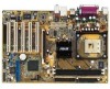
...PCI frequencies ASUS C.P.R. (CPU Parameter Recall) Rear panel I/O 1 x Parallel port 1 x Serial port 1 x PS/2 keyboard port 1 x PS/2 mouse port 4 x USB 2.0 ports 1 x RJ-45 port 1 x S/PDIF out interface Line In/Line Out/Microphone ports (continued on the next page) ix P4P800S specifications summary...Mbps Fast Ethernet controller Special features Support S/PDIF out interface ASUS MyLogo2 ASUS EZ Flash ASUS C.P.R. (CPU Parameter Recall) ASUS Instant Music-Lite ASUS CrashFree BIOS 2 Extreme Overclocking AI Overclocking ASUS JumperFree CPU, Memory and AGP voltage adjustable SFS (Stepless ...
...PCI frequencies ASUS C.P.R. (CPU Parameter Recall) Rear panel I/O 1 x Parallel port 1 x Serial port 1 x PS/2 keyboard port 1 x PS/2 mouse port 4 x USB 2.0 ports 1 x RJ-45 port 1 x S/PDIF out interface Line In/Line Out/Microphone ports (continued on the next page) ix P4P800S specifications summary...Mbps Fast Ethernet controller Special features Support S/PDIF out interface ASUS MyLogo2 ASUS EZ Flash ASUS C.P.R. (CPU Parameter Recall) ASUS Instant Music-Lite ASUS CrashFree BIOS 2 Extreme Overclocking AI Overclocking ASUS JumperFree CPU, Memory and AGP voltage adjustable SFS (Stepless ...

P4P800S user's manual English version E1398
Page 10
...P4P800S specifications summary Internal I/O BIOS features Industry standard Manageability Power Requirement Form Factor Support CD contents 2 x USB 2.0 connector for 4 additional USB ports CPU/Chassis fan connectors 20-pin/4-pin ATX 12V power connectors CD/AUX/MODEM connectors Game/MIDI port connector 20-pin panel connector Front panel... audio connector 4Mb Flash ROM, AMI BIOS, ACPI, PnP, DMI2.0, WfM 2.0, SM BIOS 2.3, DMI 2.0, ASUS CrashFree BIOS 2, ASUS EZ Flash, ASUS MyLogo2 PCI 2.3, USB 2.0/1.1 DMI 2.0, WOL/WOR ...
...P4P800S specifications summary Internal I/O BIOS features Industry standard Manageability Power Requirement Form Factor Support CD contents 2 x USB 2.0 connector for 4 additional USB ports CPU/Chassis fan connectors 20-pin/4-pin ATX 12V power connectors CD/AUX/MODEM connectors Game/MIDI port connector 20-pin panel connector Front panel... audio connector 4Mb Flash ROM, AMI BIOS, ACPI, PnP, DMI2.0, WfM 2.0, SM BIOS 2.3, DMI 2.0, ASUS CrashFree BIOS 2, ASUS EZ Flash, ASUS MyLogo2 PCI 2.3, USB 2.0/1.1 DMI 2.0, WOL/WOR ...

P4P800S user's manual English version E1398
Page 13
...Sony/Philips Digital Interface (S/PDIF) jack located at the rear panel I/O. See page 1-17. See pages 1-7 and 1-26. 10/100 Mbps LAN support Easy connectivity to 2.12GB/s. The ASUS WiFi-b™ add-on USB 1.1 to play online games without...compatibility with user-friendly utilities and applications that enables enhanced graphics performance with the onboard LAN port. ASUS Wi-Fi slot The ASUS Wi-Fi slot is based on USB 2.0. Allows you to a fast 480 Mbps on the... AD1888 AC'97 audio CODEC onboard provides 6-channel audio playback for wireless LAN. ASUS P4P800S motherboard user guide 1-3
...Sony/Philips Digital Interface (S/PDIF) jack located at the rear panel I/O. See page 1-17. See pages 1-7 and 1-26. 10/100 Mbps LAN support Easy connectivity to 2.12GB/s. The ASUS WiFi-b™ add-on USB 1.1 to play online games without...compatibility with user-friendly utilities and applications that enables enhanced graphics performance with the onboard LAN port. ASUS Wi-Fi slot The ASUS Wi-Fi slot is based on USB 2.0. Allows you to a fast 480 Mbps on the... AD1888 AC'97 audio CODEC onboard provides 6-channel audio playback for wireless LAN. ASUS P4P800S motherboard user guide 1-3

P4P800S user's manual English version E1398
Page 36
...the next generation USB peripherals such as a CD-ROM, TV tuner, or MPEG card. USB+5V USB_P8USB_P8+ GND NC USB+5V USB_P6USB_P6+ GND NC P4P800S ® P4P800S USB 2.0 Header USB56 1 USB78 1 USB+5V USB_P7USB_P7+ GND USB+5V USB_P5USB_P5+ GND 1-26 Chapter 1: Product introduction Connect an optional USB 2.0/GAME module... 480 Mbps connection speed. Internal audio connectors (4-pin MODEM, CD IN, AUX IN) These connectors allow you can use the USB 2.0 capability. P4P800S ® MODEM1 Modem-In Ground Ground Modem-Out CD1(Black) Right Audio Channel Ground Ground Left Audio Channel AUX1(White...
...the next generation USB peripherals such as a CD-ROM, TV tuner, or MPEG card. USB+5V USB_P8USB_P8+ GND NC USB+5V USB_P6USB_P6+ GND NC P4P800S ® P4P800S USB 2.0 Header USB56 1 USB78 1 USB+5V USB_P7USB_P7+ GND USB+5V USB_P5USB_P5+ GND 1-26 Chapter 1: Product introduction Connect an optional USB 2.0/GAME module... 480 Mbps connection speed. Internal audio connectors (4-pin MODEM, CD IN, AUX IN) These connectors allow you can use the USB 2.0 capability. P4P800S ® MODEM1 Modem-In Ground Ground Modem-Out CD1(Black) Right Audio Channel Ground Ground Left Audio Channel AUX1(White...

P4P800S user's manual English version E1398
Page 37
... Connector MIC2 MICPWR Line out_R NC Line out_L 10. Connect the GAME/MIDI cable with yellow connector to install an Intel front panel audio cable. ASUS P4P800S motherboard user guide 1-27 Remove the caps from the Line out_R, BLINE_OUT_R, Line out_L and BLINE_OUT_L jumpers if you want to.... +5V J1B2 J1CY GND GND J1CX J1B1 +5V MIDI_IN J2B2 J2CY MIDI_OUT J2CX J2B1 +5V P4P800S ® P4P800S Game Connector GAME1 The GAME/MIDI module is an interface for the Intel front panel audio cable that allow convenient connection and control of audio devices. 9. GAME/MIDI connector (16-1...
... Connector MIC2 MICPWR Line out_R NC Line out_L 10. Connect the GAME/MIDI cable with yellow connector to install an Intel front panel audio cable. ASUS P4P800S motherboard user guide 1-27 Remove the caps from the Line out_R, BLINE_OUT_R, Line out_L and BLINE_OUT_L jumpers if you want to.... +5V J1B2 J1CY GND GND J1CX J1B1 +5V MIDI_IN J2B2 J2CY MIDI_OUT J2CX J2B1 +5V P4P800S ® P4P800S Game Connector GAME1 The GAME/MIDI module is an interface for the Intel front panel audio cable that allow convenient connection and control of audio devices. 9. GAME/MIDI connector (16-1...

P4P800S user's manual English version E1398
Page 38
... (20 pin PANEL1) This connector accommodates several system front panel functions. PWR Ground Reset Ground P4P800S Reset SW ® IDE_LED ATX Power Switch* * Requires an ATX power supply. Pressing the power switch while in sleep mode. • System Warning ...the system power. • ATX Power Switch/Soft-off Switch Lead (2-pin PWR (light green)) This connector connects a switch that controls the system power. P4P800S System Panel Connector • System Power LED Lead (3-1 pin PLED (green)) This 3-1 pin connector connects to light up when you to hear system beeps and warnings....
... (20 pin PANEL1) This connector accommodates several system front panel functions. PWR Ground Reset Ground P4P800S Reset SW ® IDE_LED ATX Power Switch* * Requires an ATX power supply. Pressing the power switch while in sleep mode. • System Warning ...the system power. • ATX Power Switch/Soft-off Switch Lead (2-pin PWR (light green)) This connector connects a switch that controls the system power. P4P800S System Panel Connector • System Power LED Lead (3-1 pin PLED (green)) This 3-1 pin connector connects to light up when you to hear system beeps and warnings....
P4P800S user's manual English version E1398
Page 40
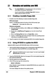
...a. c. Write down the BIOS file name to create a bootable floppy disk. Visit the ASUS website (www.asus.com) to a bootable floppy disk. Copy the AFUDOS.EXE utility from the support CD ...latest BIOS file for this motherboard is in the root directory of the support CD filenamed "P4P800.ROM". • Copy the original BIOS to a bootable floppy disk in case you copied ... motherboard. d. Insert a 1.44 MB floppy disk when prompted. Boot the system from the Control Panel window. Copy the original (or the latest) motherboard BIOS to the bootable floppy disk. 2.1.2 Using...
...a. c. Write down the BIOS file name to create a bootable floppy disk. Visit the ASUS website (www.asus.com) to a bootable floppy disk. Copy the AFUDOS.EXE utility from the support CD ...latest BIOS file for this motherboard is in the root directory of the support CD filenamed "P4P800.ROM". • Copy the original BIOS to a bootable floppy disk in case you copied ... motherboard. d. Insert a 1.44 MB floppy disk when prompted. Boot the system from the Control Panel window. Copy the original (or the latest) motherboard BIOS to the bootable floppy disk. 2.1.2 Using...

P4P800S user's manual English version E1398
Page 82
...headphone to the Line Out (lime colored) port on the drive. 5. Place an audio CD on the rear panel for audio output. Press F2 or Enter once to turn ON Instant Music Lite. 6. You may also connect... a grounded power source, so that the power cord is no CD on the CD-ROM drive front panel. 4. If there is plugged to the headphone jack on the drive and you enabled the Instant Music ...CD ON/OFF CAPS SCROLL LOCK LOCK LED LED PLAY/PAUSE STOP/EJECT PREVIOUS NEXT VOL. To use ASUS Instant Music Lite: 1. DOWN VOL. Press F1 or the Space Bar to select other tracks or control...
...headphone to the Line Out (lime colored) port on the drive. 5. Place an audio CD on the rear panel for audio output. Press F2 or Enter once to turn ON Instant Music Lite. 6. You may also connect... a grounded power source, so that the power cord is no CD on the CD-ROM drive front panel. 4. If there is plugged to the headphone jack on the drive and you enabled the Instant Music ...CD ON/OFF CAPS SCROLL LOCK LOCK LED LED PLAY/PAUSE STOP/EJECT PREVIOUS NEXT VOL. To use ASUS Instant Music Lite: 1. DOWN VOL. Press F1 or the Space Bar to select other tracks or control...


