Motherboard DIY Troubleshooting Guide
Page 6
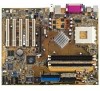
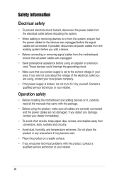
... by yourself. Contact a qualified service technician or your dealer immediately. • To avoid short circuits, keep paper clips, screws, and staples away from connectors, slots, sockets and circuitry. • Avoid dust, humidity, and temperature extremes. Operation safety • Before installing the motherboard and adding devices on a stable surface. • If you...
... by yourself. Contact a qualified service technician or your dealer immediately. • To avoid short circuits, keep paper clips, screws, and staples away from connectors, slots, sockets and circuitry. • Avoid dust, humidity, and temperature extremes. Operation safety • Before installing the motherboard and adding devices on a stable surface. • If you...
Motherboard DIY Troubleshooting Guide
Page 9
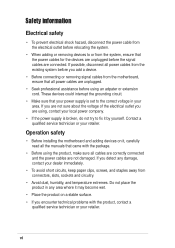
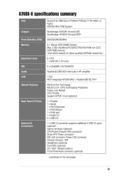
...; nForce2 400 Southbridge: NVIDIA® nForce2 MCP 400/333/266/200Mhz 3 x 184-pin DDR DIMM Sockets Max. 3 GB unbuffered PC3200/2700/2100/1600 non-ECC DDR RAM memory. (Visit ASUS website for latest qualified DDR400 module list.) 5 x PCI 1 x AGP 8X (1.5V only) 2 ...x UltraDMA 133/100/66/33 Realtek ALC650 6CH with built-in HP amplifier 1 Port MCP integrated NVIDIA MAC + Realtek 8201BL PHY ASUS Q-Fan Technology ASUS C.O.P. (CPU Overheating Protection) Power Loss Restart CPU Throttle Support S/PDIF in/out (optional) 1 x Parallel 1 x Serial 1 x PS/2 Keyboard 1 x PS/2 Mouse 1 x RJ45 ...
...; nForce2 400 Southbridge: NVIDIA® nForce2 MCP 400/333/266/200Mhz 3 x 184-pin DDR DIMM Sockets Max. 3 GB unbuffered PC3200/2700/2100/1600 non-ECC DDR RAM memory. (Visit ASUS website for latest qualified DDR400 module list.) 5 x PCI 1 x AGP 8X (1.5V only) 2 ...x UltraDMA 133/100/66/33 Realtek ALC650 6CH with built-in HP amplifier 1 Port MCP integrated NVIDIA MAC + Realtek 8201BL PHY ASUS Q-Fan Technology ASUS C.O.P. (CPU Overheating Protection) Power Loss Restart CPU Throttle Support S/PDIF in/out (optional) 1 x Parallel 1 x Serial 1 x PS/2 Keyboard 1 x PS/2 Mouse 1 x RJ45 ...
Motherboard DIY Troubleshooting Guide
Page 12
... Technology and more are included to deliver the maximum performance for buying the ASUS® A7N8X-X motherboard! Before you for socket A processors. 1.1 Welcome! For future upgrades or system reconfiguration, this chapter provides technical information about the motherboard. Thank you start installing the motherboard and hardware devices ...
... Technology and more are included to deliver the maximum performance for buying the ASUS® A7N8X-X motherboard! Before you for socket A processors. 1.1 Welcome! For future upgrades or system reconfiguration, this chapter provides technical information about the motherboard. Thank you start installing the motherboard and hardware devices ...
Motherboard DIY Troubleshooting Guide
Page 14
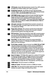
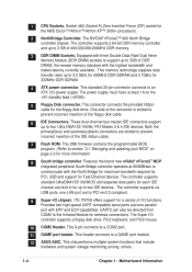
...® nForce2™ 400 North Bridge controller chipset. This memory technology supplies data transfer rates up to a GAME port module. 12 ASUS ASIC. This 9-pin connects to 3.2 GB/s for 400MHz DDR SDRAM and 2.7GB/s for wireless connections. This header connects to 3GB ...This chip performs multiple system functions that include hardware and system voltage monitoring among others. 1-4 Chapter 1: Motherboard Information Socket 462 (Socket A) Zero Insertion Force (ZIF) socket for each IDE channel are slotted to prevent incorrect insertion of the IDE ribbon cable. 7 Flash ROM. These...
...® nForce2™ 400 North Bridge controller chipset. This memory technology supplies data transfer rates up to a GAME port module. 12 ASUS ASIC. This 9-pin connects to 3.2 GB/s for 400MHz DDR SDRAM and 2.7GB/s for wireless connections. This header connects to 3GB ...This chip performs multiple system functions that include hardware and system voltage monitoring among others. 1-4 Chapter 1: Motherboard Information Socket 462 (Socket A) Zero Insertion Force (ZIF) socket for each IDE channel are slotted to prevent incorrect insertion of the IDE ribbon cable. 7 Flash ROM. These...
Motherboard DIY Troubleshooting Guide
Page 16
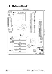
30.5cm (12.0in) 1.4 Motherboard layout PS/2 T: Mouse B: Keyboard USB3 USB4 COM1 24.5cm (9.64in) KBPWR1 USBPWR_34 Socket 462 CPU_FAN1 ATX Power Connector DDR DIMM1 (64/72 bit, 184-pin module) DDR DIMM2 (64/72 bit, 184-pin module) DDR DIMM3 (64/72 ...) PCI 1 PCI 2 ®A7N8X-X PCI 3 nForce2 MCP Chipset CR2032 3V Lithium Cell CMOS Power CLRTC1 2Mb BIOS Super I/O USB56 COM2 MODEM1 PWR_LED1 PCI 4 PCI 5 USBPWR_56 ASUS ASIC with Hardware Monitor GAME1 IR_CON1 IDELED1 PWRTMP1 CHASSIS1 CTRL_PANEL1 1-6 Chapter 1: Motherboard Information
30.5cm (12.0in) 1.4 Motherboard layout PS/2 T: Mouse B: Keyboard USB3 USB4 COM1 24.5cm (9.64in) KBPWR1 USBPWR_34 Socket 462 CPU_FAN1 ATX Power Connector DDR DIMM1 (64/72 bit, 184-pin module) DDR DIMM2 (64/72 bit, 184-pin module) DDR DIMM3 (64/72 ...) PCI 1 PCI 2 ®A7N8X-X PCI 3 nForce2 MCP Chipset CR2032 3V Lithium Cell CMOS Power CLRTC1 2Mb BIOS Super I/O USB56 COM2 MODEM1 PWR_LED1 PCI 4 PCI 5 USBPWR_56 ASUS ASIC with Hardware Monitor GAME1 IR_CON1 IDELED1 PWRTMP1 CHASSIS1 CTRL_PANEL1 1-6 Chapter 1: Motherboard Information
Motherboard DIY Troubleshooting Guide
Page 17
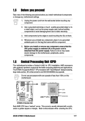
... is usually indicated with the component. 5. ASUS A7N8X-X Motherboard 1-7 Whenever you uninstall any component. 2. Hold components by the edges to avoid touching the ICs on them due to this motherboard. ® A7N8X-X CPU NOTCH TO INNER CORNER AMD™ CPU LOCK LEVER CPU NOTCH A7N8X-X Socket 462 Each AMD CPU has a "marked...
... is usually indicated with the component. 5. ASUS A7N8X-X Motherboard 1-7 Whenever you uninstall any component. 2. Hold components by the edges to avoid touching the ICs on them due to this motherboard. ® A7N8X-X CPU NOTCH TO INNER CORNER AMD™ CPU LOCK LEVER CPU NOTCH A7N8X-X Socket 462 Each AMD CPU has a "marked...
Motherboard DIY Troubleshooting Guide
Page 18
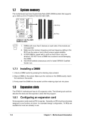
... [Auto] ensure system stability. 3. Make sure the notches on the socket. 1.7 System memory The motherboard has three Double Data Rate (DDR) DIMM sockets that they support. 1.8.1 Configuring an expansion card Some expansion cards need an IRQ to operate. Visit ASUS website (www.asus.com) for latest DDR400 Qualified Vendor List. 1.7.1 Installing a DIMM 1. Generally, an...
... [Auto] ensure system stability. 3. Make sure the notches on the socket. 1.7 System memory The motherboard has three Double Data Rate (DDR) DIMM sockets that they support. 1.8.1 Configuring an expansion card Some expansion cards need an IRQ to operate. Visit ASUS website (www.asus.com) for latest DDR400 Qualified Vendor List. 1.7.1 Installing a DIMM 1. Generally, an...
A7N8X-X User's Manual
Page 6
... the correct voltage in any damage, contact your dealer immediately. • To avoid short circuits, keep paper clips, screws, and staples away from connectors, slots, sockets and circuitry. • Avoid dust, humidity, and temperature extremes.
... the correct voltage in any damage, contact your dealer immediately. • To avoid short circuits, keep paper clips, screws, and staples away from connectors, slots, sockets and circuitry. • Avoid dust, humidity, and temperature extremes.
A7N8X-X User's Manual
Page 9
...; nForce2 400 Southbridge: NVIDIA® nForce2 MCP 400/333/266/200Mhz 3 x 184-pin DDR DIMM Sockets Max. 3 GB unbuffered PC3200/2700/2100/1600 non-ECC DDR RAM memory. (Visit ASUS website for latest qualified DDR400 module list.) 5 x PCI 1 x AGP 8X (1.5V only) 2 ...x UltraDMA 133/100/66/33 Realtek ALC650 6CH with built-in HP amplifier 1 Port MCP integrated NVIDIA MAC + Realtek 8201BL PHY ASUS Q-Fan Technology ASUS C.O.P. (CPU Overheating Protection) Power Loss Restart CPU Throttle Support S/PDIF in/out (optional) 1 x Parallel 1 x Serial 1 x PS/2 Keyboard 1 x PS/2 Mouse 1 x RJ45 ...
...; nForce2 400 Southbridge: NVIDIA® nForce2 MCP 400/333/266/200Mhz 3 x 184-pin DDR DIMM Sockets Max. 3 GB unbuffered PC3200/2700/2100/1600 non-ECC DDR RAM memory. (Visit ASUS website for latest qualified DDR400 module list.) 5 x PCI 1 x AGP 8X (1.5V only) 2 ...x UltraDMA 133/100/66/33 Realtek ALC650 6CH with built-in HP amplifier 1 Port MCP integrated NVIDIA MAC + Realtek 8201BL PHY ASUS Q-Fan Technology ASUS C.O.P. (CPU Overheating Protection) Power Loss Restart CPU Throttle Support S/PDIF in/out (optional) 1 x Parallel 1 x Serial 1 x PS/2 Keyboard 1 x PS/2 Mouse 1 x RJ45 ...

A7N8X-X User's Manual
Page 12
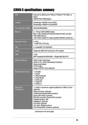
...you for the following items. 1-2 The ASUS A7N8X-X motherboard is loaded with value-added features for socket A processors. This motherboard is loaded with the list below. 1.2 Package contents ASUS A7N8X-X motherboard ATX form factor: 12 in x 9.6 in ASUS A7N8X-X series support CD 40-pin 80... User's Manual Check your package with the most advanced technologies to ensure the best user experience and value in your ASUS A7N8X-X package for buying the ASUS® A7N8X-X motherboard! 1.1 Welcome! Thank you start installing the motherboard and hardware devices on it, check the ...
...you for the following items. 1-2 The ASUS A7N8X-X motherboard is loaded with value-added features for socket A processors. This motherboard is loaded with the list below. 1.2 Package contents ASUS A7N8X-X motherboard ATX form factor: 12 in x 9.6 in ASUS A7N8X-X series support CD 40-pin 80... User's Manual Check your package with the most advanced technologies to ensure the best user experience and value in your ASUS A7N8X-X package for buying the ASUS® A7N8X-X motherboard! 1.1 Welcome! Thank you start installing the motherboard and hardware devices on it, check the ...
A7N8X-X User's Manual
Page 14
...and is slotted to 3 GB of the floppy disk cable. COM2 Header. This header connects to an ATX 12V power supply. ASUS ASIC. 1 2 CPU Sockets. NorthBridge Controller. Equipped with the highest bandwidth and lowest latency currently available. The power supply must have at 800MB/sec to a ...port with the North Bridge for maximum bandwith required for PCI, USB and support for wireless connections. GAME port header. Socket 462 (Socket A) Zero Insertion Force (ZIF) socket for the floppy disk drive. This standard 20-pin connector connects to a GAME port module. Both the primary(blue)...
...and is slotted to 3 GB of the floppy disk cable. COM2 Header. This header connects to an ATX 12V power supply. ASUS ASIC. 1 2 CPU Sockets. NorthBridge Controller. Equipped with the highest bandwidth and lowest latency currently available. The power supply must have at 800MB/sec to a ...port with the North Bridge for maximum bandwith required for PCI, USB and support for wireless connections. GAME port header. Socket 462 (Socket A) Zero Insertion Force (ZIF) socket for the floppy disk drive. This standard 20-pin connector connects to a GAME port module. Both the primary(blue)...

A7N8X-X User's Manual
Page 16
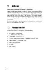
1.4 T: Mouse B: Keyboard Motherboard layout 24.5cm (9.64in) KBPWR1 PS/2 Socket 462 DDR DIMM1 (64/72 bit, 184-pin module) DDR DIMM2 (64/72 bit, 184-pin module) CPU_FAN1 USB3 USB4 COM1 USBPWR_34 DDR DIMM3 (64/... 2 ® Super I/O A7N8X-X CR2032 3V Lithium Cell CMOS Power CLRTC1 COM2 USB56 PCI 3 PCI 4 MODEM1 PWR_LED1 USBPWR_56 GAME1 PCI 5 with Hardware Monitor IDELED1 PWRTMP1 CHASSIS1 ASUS ASIC IR_CON1 CTRL_PANEL1 1-6 Chapter 1: Motherboard Information PRI_IDE1 30.5cm (12.0in) USB1 RJ-45 USB2 Top: nForce2 400 Chipset CPU_FSB FLOPPY1 nVidia ATX Power Connector
1.4 T: Mouse B: Keyboard Motherboard layout 24.5cm (9.64in) KBPWR1 PS/2 Socket 462 DDR DIMM1 (64/72 bit, 184-pin module) DDR DIMM2 (64/72 bit, 184-pin module) CPU_FAN1 USB3 USB4 COM1 USBPWR_34 DDR DIMM3 (64/... 2 ® Super I/O A7N8X-X CR2032 3V Lithium Cell CMOS Power CLRTC1 COM2 USB56 PCI 3 PCI 4 MODEM1 PWR_LED1 USBPWR_56 GAME1 PCI 5 with Hardware Monitor IDELED1 PWRTMP1 CHASSIS1 ASUS ASIC IR_CON1 CTRL_PANEL1 1-6 Chapter 1: Motherboard Information PRI_IDE1 30.5cm (12.0in) USB1 RJ-45 USB2 Top: nForce2 400 Chipset CPU_FSB FLOPPY1 nVidia ATX Power Connector

A7N8X-X User's Manual
Page 17
... them . 4. CPU NOTCH TO INNER CORNER LOCK LEVER ® A7N8X-X AMD™ CPU CPU NOTCH A7N8X-X Socket 462 Each AMD CPU has a "marked" corner. Failure to do so may cause severe damage to static electricity. 3. ASUS A7N8X-X Motherboard 1-7 Whenever you install or remove any component, ensure that came with a notch, and/or...
... them . 4. CPU NOTCH TO INNER CORNER LOCK LEVER ® A7N8X-X AMD™ CPU CPU NOTCH A7N8X-X Socket 462 Each AMD CPU has a "marked" corner. Failure to do so may cause severe damage to static electricity. 3. ASUS A7N8X-X Motherboard 1-7 Whenever you install or remove any component, ensure that came with a notch, and/or...

A7N8X-X User's Manual
Page 18
... stability. 3. A DDR DIMM is keyed with more than 8 devices on each side of the module are already in the socket. 3. Unlock a DIMM socket by pressing the retaining clips outward. 2. The following sub-sections describe the slots and the expansion cards that supports up to ... (www.asus.com) for latest DDR400 Qualified Vendor List. 1.7.1 Installing a DIMM 1. Generally, an IRQ must be exclusively assigned to one direction. Make sure the notches on the socket. 1.7 System memory The motherboard has three Double Data Rate (DDR) DIMM sockets that they support. 1.8.1 Configuring an...
... stability. 3. A DDR DIMM is keyed with more than 8 devices on each side of the module are already in the socket. 3. Unlock a DIMM socket by pressing the retaining clips outward. 2. The following sub-sections describe the slots and the expansion cards that supports up to ... (www.asus.com) for latest DDR400 Qualified Vendor List. 1.7.1 Installing a DIMM 1. Generally, an IRQ must be exclusively assigned to one direction. Make sure the notches on the socket. 1.7 System memory The motherboard has three Double Data Rate (DDR) DIMM sockets that they support. 1.8.1 Configuring an...


