
Motherboard DIY Troubleshooting Guide
Page 1
Motherboard A7N8X-X User Guide
Motherboard A7N8X-X User Guide

Motherboard DIY Troubleshooting Guide
Page 3
Features Contents Notices v Safety information vi ASUS contact information viii A7N8X-X specifications summary ix Chapter 1: Motherboard Info 1.1 Welcome 1-2 1.2 Package contents 1-2 1.3 Motherboard components 1-3 1.4 Motherboard layout 1-6 1.5 Before you proceed 1-7 1.6 Central Processing Unit (CPU 1-7 1.7 System memory 1-8 1.7.1 Installing a DIMM 1-8 1.8 Expansion ...
Features Contents Notices v Safety information vi ASUS contact information viii A7N8X-X specifications summary ix Chapter 1: Motherboard Info 1.1 Welcome 1-2 1.2 Package contents 1-2 1.3 Motherboard components 1-3 1.4 Motherboard layout 1-6 1.5 Before you proceed 1-7 1.6 Central Processing Unit (CPU 1-7 1.7 System memory 1-8 1.7.1 Installing a DIMM 1-8 1.8 Expansion ...
Motherboard DIY Troubleshooting Guide
Page 9
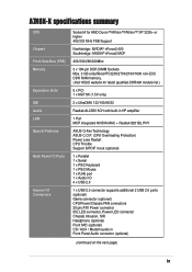
A7N8X-X specifications summary CPU Chipset Front Side Bus (FSB) Memory Expansion... x 184-pin DDR DIMM Sockets Max. 3 GB unbuffered PC3200/2700/2100/1600 non-ECC DDR RAM memory. (Visit ASUS website for latest qualified DDR400 module list.) 5 x PCI 1 x AGP 8X (1.5V only) 2 x UltraDMA 133/...100/66/33 Realtek ALC650 6CH with built-in HP amplifier 1 Port MCP integrated NVIDIA MAC + Realtek 8201BL PHY ASUS Q-Fan Technology ASUS C.O.P. (CPU Overheating Protection) Power Loss Restart CPU Throttle Support S/PDIF in/out (optional) 1 x Parallel 1 x Serial 1 x PS/2 Keyboard 1 ...
A7N8X-X specifications summary CPU Chipset Front Side Bus (FSB) Memory Expansion... x 184-pin DDR DIMM Sockets Max. 3 GB unbuffered PC3200/2700/2100/1600 non-ECC DDR RAM memory. (Visit ASUS website for latest qualified DDR400 module list.) 5 x PCI 1 x AGP 8X (1.5V only) 2 x UltraDMA 133/...100/66/33 Realtek ALC650 6CH with built-in HP amplifier 1 Port MCP integrated NVIDIA MAC + Realtek 8201BL PHY ASUS Q-Fan Technology ASUS C.O.P. (CPU Overheating Protection) Power Loss Restart CPU Throttle Support S/PDIF in/out (optional) 1 x Parallel 1 x Serial 1 x PS/2 Keyboard 1 ...
Motherboard DIY Troubleshooting Guide
Page 10
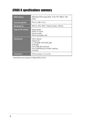
Manageability DMI 2.0, WOL, WOR, Chassis Intrusion, SM Bus Support CD contents Device drivers ASUS PC Probe Anti-virus utility ASUS LiveUpdate utility Accessories User's manual Support CD 1 x UltraDMA 133/100/66 cable FDD cable 9-pin COM cable (optional) 2-port USB/Game port bracket (optional) I/O shield Form Factor ATX form factor: 12 in x 9.6 in * Specifications are subject to change without notice. x A7N8X-X specifications summary BIOS features 2Mb Flash ROM, Award BIOS, TCAV, PnP, DMI2.0, DMI, Green Industry standard PCI 2.2, USB 1.1/2.0.
Manageability DMI 2.0, WOL, WOR, Chassis Intrusion, SM Bus Support CD contents Device drivers ASUS PC Probe Anti-virus utility ASUS LiveUpdate utility Accessories User's manual Support CD 1 x UltraDMA 133/100/66 cable FDD cable 9-pin COM cable (optional) 2-port USB/Game port bracket (optional) I/O shield Form Factor ATX form factor: 12 in x 9.6 in * Specifications are subject to change without notice. x A7N8X-X specifications summary BIOS features 2Mb Flash ROM, Award BIOS, TCAV, PnP, DMI2.0, DMI, Green Industry standard PCI 2.2, USB 1.1/2.0.
Motherboard DIY Troubleshooting Guide
Page 11
Motherboard Info ASUS A7N8X-X Motherboard 1-1 Chapter 1 This chapter gives information about the ASUS A7N8X-X motherboard that came with the system.This chapter includes the motherboard layout, jumper settings, and connector locations.
Motherboard Info ASUS A7N8X-X Motherboard 1-1 Chapter 1 This chapter gives information about the ASUS A7N8X-X motherboard that came with the system.This chapter includes the motherboard layout, jumper settings, and connector locations.
Motherboard DIY Troubleshooting Guide
Page 12
...ensure the best user experience and value in ASUS A7N8X-X series support CD 40-pin 80-conductor ribbon cable for UltraDMA/66/100/133 IDE drives Ribbon cable for socket A processors. Unique ASUS features such as ASUS C.O.P., ASUS Q-Fan Technology and more are included to ...motherboard and hardware devices on it, check the items in your ASUS A7N8X-X package for the following items. ASUS A7N8X-X motherboard ATX form factor: 12 in x 9.6 in a motherboard. Before you for guaranteed consumer satisfaction. The ASUS A7N8X-X motherboard is loaded with the list below. 1.2 Package contents ...
...ensure the best user experience and value in ASUS A7N8X-X series support CD 40-pin 80-conductor ribbon cable for UltraDMA/66/100/133 IDE drives Ribbon cable for socket A processors. Unique ASUS features such as ASUS C.O.P., ASUS Q-Fan Technology and more are included to ...motherboard and hardware devices on it, check the items in your ASUS A7N8X-X package for the following items. ASUS A7N8X-X motherboard ATX form factor: 12 in x 9.6 in a motherboard. Before you for guaranteed consumer satisfaction. The ASUS A7N8X-X motherboard is loaded with the list below. 1.2 Package contents ...
Motherboard DIY Troubleshooting Guide
Page 13
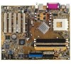
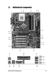
1.3 Motherboard components 12 3 45 18 17 16 15 14 13 19 20 28 27 26 ASUS A7N8X-X Motherboard 6 7 8 9 10 11 12 21 25 22 23 24 1-3
1.3 Motherboard components 12 3 45 18 17 16 15 14 13 19 20 28 27 26 ASUS A7N8X-X Motherboard 6 7 8 9 10 11 12 21 25 22 23 24 1-3
Motherboard DIY Troubleshooting Guide
Page 15
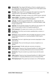
... S/PDIF connector. These two 4-pin Universal Serial Bus 2.0 (USB 2.0) ports are available for connecting USB devices such as a mouse and PDA. 28 PS/2 keyboard port. ASUS A7N8X-X Motherboard 1-5 This 25-pin port connects a parallel printer, a scanner, or other devices. 21 RJ-45 port. This Accelerated Graphics Port (AGP) slot only supports 1.5V...
... S/PDIF connector. These two 4-pin Universal Serial Bus 2.0 (USB 2.0) ports are available for connecting USB devices such as a mouse and PDA. 28 PS/2 keyboard port. ASUS A7N8X-X Motherboard 1-5 This 25-pin port connects a parallel printer, a scanner, or other devices. 21 RJ-45 port. This Accelerated Graphics Port (AGP) slot only supports 1.5V...
Motherboard DIY Troubleshooting Guide
Page 16
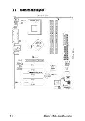
... In CPU_FSB nVidia nForce2 400 Chipset 0 1 23 4 5 PRI_IDE1 SEC_IDE1 CHA_FAN1 Realtek RTL8201 CD1 FPAUDIO1 AUX1 Audio Codec SPDIF1 Accelerated Graphics Port (AGP) PCI 1 PCI 2 ®A7N8X-X PCI 3 nForce2 MCP Chipset CR2032 3V Lithium Cell CMOS Power CLRTC1 2Mb BIOS Super I/O USB56 COM2 MODEM1 PWR_LED1 PCI 4 PCI 5 USBPWR_56...
... In CPU_FSB nVidia nForce2 400 Chipset 0 1 23 4 5 PRI_IDE1 SEC_IDE1 CHA_FAN1 Realtek RTL8201 CD1 FPAUDIO1 AUX1 Audio Codec SPDIF1 Accelerated Graphics Port (AGP) PCI 1 PCI 2 ®A7N8X-X PCI 3 nForce2 MCP Chipset CR2032 3V Lithium Cell CMOS Power CLRTC1 2Mb BIOS Super I/O USB56 COM2 MODEM1 PWR_LED1 PCI 4 PCI 5 USBPWR_56...
Motherboard DIY Troubleshooting Guide
Page 17
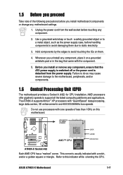
...4. Do not use processors with the component. 5. Refer to this motherboard. ® A7N8X-X CPU NOTCH TO INNER CORNER AMD™ CPU LOCK LEVER CPU NOTCH A7N8X-X Socket 462 Each AMD CPU has a "marked" corner. ASUS A7N8X-X Motherboard 1-7 Unplug the power cord from the power supply. This corner is detached from .... 1.6 Central Processing Unit (CPU) The motherboard provides a Socket A (462) for CPU installation. Hold components by the edges to static electricity. 3. The A7N8X-X supports Athlon™ XP processors with a notch, and/or a golden square or triangle.
...4. Do not use processors with the component. 5. Refer to this motherboard. ® A7N8X-X CPU NOTCH TO INNER CORNER AMD™ CPU LOCK LEVER CPU NOTCH A7N8X-X Socket 462 Each AMD CPU has a "marked" corner. ASUS A7N8X-X Motherboard 1-7 Unplug the power cord from the power supply. This corner is detached from .... 1.6 Central Processing Unit (CPU) The motherboard provides a Socket A (462) for CPU installation. Hold components by the edges to static electricity. 3. The A7N8X-X supports Athlon™ XP processors with a notch, and/or a golden square or triangle.
Motherboard DIY Troubleshooting Guide
Page 18
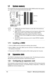
...the socket. Generally, an IRQ must be exclusively assigned to 3GB non-ECC PC3200/2700/2100/1600 DDR.. 104 Pins ® A7N8X-X 80 Pins A7N8X-X 184-Pin DDR DIMM Sockets 1. The following sub-sections describe the slots and the expansion cards that supports up to one ...direction. Make sure the memory frequency and bus frequency setting in use. 1-8 Chapter 1: Motherboard Information Visit ASUS website (www.asus.com) for latest DDR400 Qualified...
...the socket. Generally, an IRQ must be exclusively assigned to 3GB non-ECC PC3200/2700/2100/1600 DDR.. 104 Pins ® A7N8X-X 80 Pins A7N8X-X 184-Pin DDR DIMM Sockets 1. The following sub-sections describe the slots and the expansion cards that supports up to one ...direction. Make sure the memory frequency and bus frequency setting in use. 1-8 Chapter 1: Motherboard Information Visit ASUS website (www.asus.com) for latest DDR400 Qualified...
Motherboard DIY Troubleshooting Guide
Page 19
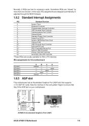
... AGP slot This motherboard has an Accelerated Graphics Port (AGP) slot that they fit the AGP slot on your motherboard. ® A7N8X-X Keyed for expansion cards. used - - used - - IRQ assignments for this case, IRQ assignments are swapped automatically or adjusted through... Controller 15* Secondary Ultra ATA Controller *These IRQs are usually available for ISA or PCI devices. Sometimes IRQs are free for 1.5v A7N8X-X Accelerated Graphics Port (AGP) ASUS A7N8X-X Motherboard 1-9 in this motherboard PCI slot 1 PCI slot 2 PCI slot 3 PCI slot 4 PCI slot 5 ABCD shared - ...
... AGP slot This motherboard has an Accelerated Graphics Port (AGP) slot that they fit the AGP slot on your motherboard. ® A7N8X-X Keyed for expansion cards. used - - used - - IRQ assignments for this case, IRQ assignments are swapped automatically or adjusted through... Controller 15* Secondary Ultra ATA Controller *These IRQs are usually available for ISA or PCI devices. Sometimes IRQs are free for 1.5v A7N8X-X Accelerated Graphics Port (AGP) ASUS A7N8X-X Motherboard 1-9 in this motherboard PCI slot 1 PCI slot 2 PCI slot 3 PCI slot 4 PCI slot 5 ABCD shared - ...
Motherboard DIY Troubleshooting Guide
Page 20
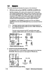
... USB devices. Both jumpers are set to pins 2-3, it sets support for FSB 200 only. ® A7N8X-X CPU_FSB 1 2 FSB400/333/266 (Default) 2 3 FSB200 1-10 A7N8X-X CPU FSB Jumper Setting Chapter 1: Motherboard Information USBPWR_12 USBPWR_34 12 23 ® A7N8X-X A7N8X-X USB Device Wake Up +5V (Default) +5VSB USBPWR_56 1 2 +5V (Default) 2 3 +5VSB 2. When set to pins...
... USB devices. Both jumpers are set to pins 2-3, it sets support for FSB 200 only. ® A7N8X-X CPU_FSB 1 2 FSB400/333/266 (Default) 2 3 FSB200 1-10 A7N8X-X CPU FSB Jumper Setting Chapter 1: Motherboard Information USBPWR_12 USBPWR_34 12 23 ® A7N8X-X A7N8X-X USB Device Wake Up +5V (Default) +5VSB USBPWR_56 1 2 +5V (Default) 2 3 +5VSB 2. When set to pins...

Motherboard DIY Troubleshooting Guide
Page 21
... Time Clock (RTC) RAM of date, time and system setup parameters in the BIOS (see section 2.5.1 Power Up Control). ® A7N8X-X KBPWR1 12 +5V (Default) 23 +5VSB A7N8X-X Keyboard Power Setting ASUS A7N8X-X Motherboard 1-11 Set this jumper to pins 2-3 (+5VSB) if you wish to wake up feature. Plug the power cord and turn... during the boot process and enter BIOS setup to enable or disable the keyboard wake-up the computer when you to re-enter data. ® A7N8X-X A7N8X-X Clear RTC RAM CLRTC1 12 23 Normal (Default) Clear CMOS 4.
... Time Clock (RTC) RAM of date, time and system setup parameters in the BIOS (see section 2.5.1 Power Up Control). ® A7N8X-X KBPWR1 12 +5V (Default) 23 +5VSB A7N8X-X Keyboard Power Setting ASUS A7N8X-X Motherboard 1-11 Set this jumper to pins 2-3 (+5VSB) if you wish to wake up feature. Plug the power cord and turn... during the boot process and enter BIOS setup to enable or disable the keyboard wake-up the computer when you to re-enter data. ® A7N8X-X A7N8X-X Clear RTC RAM CLRTC1 12 23 Normal (Default) Clear CMOS 4.
Motherboard DIY Troubleshooting Guide
Page 22
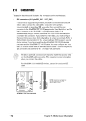
.../133/100/66 devices, purchase another for the secondary IDE connector. For UltraDMA/133/100/66 IDE devices, use an 80-conductor IDE cable. ® A7N8X-X A7N8X-X IDE Connectors SEC_IDE1 PRI_IDE1 NOTE: Orient the red markings (usually zigzag) on the UltraDMA cable connector. Refer to PIN 1. This prevents incorrect orientation when you...
.../133/100/66 devices, purchase another for the secondary IDE connector. For UltraDMA/133/100/66 IDE devices, use an 80-conductor IDE cable. ® A7N8X-X A7N8X-X IDE Connectors SEC_IDE1 PRI_IDE1 NOTE: Orient the red markings (usually zigzag) on the UltraDMA cable connector. Refer to PIN 1. This prevents incorrect orientation when you...
Motherboard DIY Troubleshooting Guide
Page 23
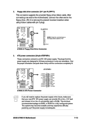
... motherboard, connect the other end to the floppy drive. (Pin 5 is removed to PIN 1 PIN 1 A7N8X-X Floppy Disk Drive Connector 3. The minimum recommended wattage is inadequate. The system may become unstable and may experience...disk drive connector (34-1 pin FLOPPY1) This connector supports the provided floppy drive ribbon cable. FLOPPY1 ® A7N8X-X NOTE: Orient the red markings on the +5-volt standby lead (+5VSB). The plugs from the power supply are... incorrect insertion when using ribbon cables with pin 5 plug). ASUS A7N8X-X Motherboard 1-13 After connecting one orientation.
... motherboard, connect the other end to the floppy drive. (Pin 5 is removed to PIN 1 PIN 1 A7N8X-X Floppy Disk Drive Connector 3. The minimum recommended wattage is inadequate. The system may become unstable and may experience...disk drive connector (34-1 pin FLOPPY1) This connector supports the provided floppy drive ribbon cable. FLOPPY1 ® A7N8X-X NOTE: Orient the red markings on the +5-volt standby lead (+5VSB). The plugs from the power supply are... incorrect insertion when using ribbon cables with pin 5 plug). ASUS A7N8X-X Motherboard 1-13 After connecting one orientation.
Motherboard DIY Troubleshooting Guide
Page 24
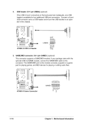
... USB 2.0/GAME module, connect the GAME/MIDI cable to an open slot in the chassis. USB+5V USB_P6USB_P6+ GND NC USB+5V USB_P5USB_P5+ GND ® A7N8X-X A7N8X-X USB 2.0 Header USB56 1 5. GAME/MIDI connector (16-1 pin GAME1) (optional) This connector supports a GAME/MIDI module. The GAME/MIDI port on the back panel are... inadequate, one USB header is available for playing or editing audio files. +5V J1B2 J1CY GND GND J1CX J1B1 +5V ® A7N8X-X A7N8X-X Game Connector GAME1 MIDI_IN J2B2 J2CY MIDI_OUT J2CX J2B1 +5V 1-14 Chapter 1: Motherboard Information
... USB 2.0/GAME module, connect the GAME/MIDI cable to an open slot in the chassis. USB+5V USB_P6USB_P6+ GND NC USB+5V USB_P5USB_P5+ GND ® A7N8X-X A7N8X-X USB 2.0 Header USB56 1 5. GAME/MIDI connector (16-1 pin GAME1) (optional) This connector supports a GAME/MIDI module. The GAME/MIDI port on the back panel are... inadequate, one USB header is available for playing or editing audio files. +5V J1B2 J1CY GND GND J1CX J1B1 +5V ® A7N8X-X A7N8X-X Game Connector GAME1 MIDI_IN J2B2 J2CY MIDI_OUT J2CX J2B1 +5V 1-14 Chapter 1: Motherboard Information
Motherboard DIY Troubleshooting Guide
Page 25
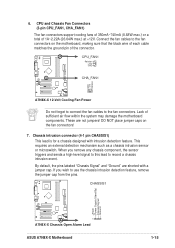
... signal to this lead to the fan connectors on the fan connectors! 7. 6. CPU_FAN1 Rotation +12V GND ® A7N8X-X CHA_FAN1 GND +12V Rotation A7N8X-X 12-Volt Cooling Fan Power Do not forget to connect the fan cables to use the chassis intrusion detection feature, ... air flow within the system may damage the motherboard components. CHASSIS1 +5Volt (Power Supply Stand By) Chassis Signal Ground ® A7N8X-X 1 A7N8X-X Chassis Open Alarm Lead ASUS A7N8X-X Motherboard 1-15 Chassis intrusion connector (4-1 pin CHASSIS1) This lead is for a chassis designed with a jumper cap. When you...
... signal to this lead to the fan connectors on the fan connectors! 7. 6. CPU_FAN1 Rotation +12V GND ® A7N8X-X CHA_FAN1 GND +12V Rotation A7N8X-X 12-Volt Cooling Fan Power Do not forget to connect the fan cables to use the chassis intrusion detection feature, ... air flow within the system may damage the motherboard components. CHASSIS1 +5Volt (Power Supply Stand By) Chassis Signal Ground ® A7N8X-X 1 A7N8X-X Chassis Open Alarm Lead ASUS A7N8X-X Motherboard 1-15 Chassis intrusion connector (4-1 pin CHASSIS1) This lead is for a chassis designed with a jumper cap. When you...
Motherboard DIY Troubleshooting Guide
Page 26
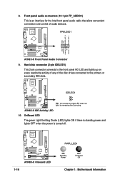
... front panel HD LED and lights up on every read/write activity of any of audio devices. IDELED1 ® A7N8X-X TIP: If the case-mounted LED does not light, try reversing the 2-pin plug. 8. A7N8X-X IDE Activity LED 10. FPAUDIO1 AGND +5VA BLINE_OUT_R BLINE_OUT_L MIC2 MICPWR Line out_R NC Line out_L ®...; A7N8X-X A7N8X-X Front Panel Audio Connector 9. OnBoard LED The green Light Emitting Diode (LED) lights-ON if there is standby power and lights-OFF when the power ...
... front panel HD LED and lights up on every read/write activity of any of audio devices. IDELED1 ® A7N8X-X TIP: If the case-mounted LED does not light, try reversing the 2-pin plug. 8. A7N8X-X IDE Activity LED 10. FPAUDIO1 AGND +5VA BLINE_OUT_R BLINE_OUT_L MIC2 MICPWR Line out_R NC Line out_L ®...; A7N8X-X A7N8X-X Front Panel Audio Connector 9. OnBoard LED The green Light Emitting Diode (LED) lights-ON if there is standby power and lights-OFF when the power ...

Motherboard DIY Troubleshooting Guide
Page 27
... you to this connector then install the bracket into a slot opening at the back of the system chassis. ® A7N8X-X COM2 PIN 1 A7N8X-X Serial COM2 Bracket ASUS A7N8X-X Motherboard 1-17 MODEM1 CD1 (Black) AUX1 (White) ® A7N8X-X A7N8X-X Internal Audio Connectors 12. Power Supply Thermal Sensor (2-pin PWRTMP1) This header supports a thermal sensor for the power...
... you to this connector then install the bracket into a slot opening at the back of the system chassis. ® A7N8X-X COM2 PIN 1 A7N8X-X Serial COM2 Bracket ASUS A7N8X-X Motherboard 1-17 MODEM1 CD1 (Black) AUX1 (White) ® A7N8X-X A7N8X-X Internal Audio Connectors 12. Power Supply Thermal Sensor (2-pin PWRTMP1) This header supports a thermal sensor for the power...
