User Guide
Page 17
... 8-port SAS2 6G RAID card LSI 8-port SAS2 6G RAID card LSI 8-port SAS2 6G RAID card ASUS Z9PA-U8 1-3 1.1 Welcome! Standard Gift Box Pack 1 1 6 1 1 1 1pc per carton Standard Bulk Pack 1 1 1 1 10pcs per carton If any of ASUS quality motherboards! The motherboard delivers a host of new features and latest technologies, making it , check the...
... 8-port SAS2 6G RAID card LSI 8-port SAS2 6G RAID card LSI 8-port SAS2 6G RAID card ASUS Z9PA-U8 1-3 1.1 Welcome! Standard Gift Box Pack 1 1 6 1 1 1 1pc per carton Standard Bulk Pack 1 1 1 1 10pcs per carton If any of ASUS quality motherboards! The motherboard delivers a host of new features and latest technologies, making it , check the...
User Guide
Page 19
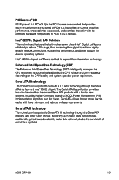
... for diverse operating systems. Intel® 82574L chipset is the PCI Express bus standard that provides twice the performance and speed of current bus systems. ASUS Z9PA-U8 1-5 Serial ATA II technology The motherboard supports the Serial ATA II 3 Gb/s technology through the Serial ATA interface and Intel® C602 chipset, delivering up...
... for diverse operating systems. Intel® 82574L chipset is the PCI Express bus standard that provides twice the performance and speed of current bus systems. ASUS Z9PA-U8 1-5 Serial ATA II technology The motherboard supports the Serial ATA II 3 Gb/s technology through the Serial ATA interface and Intel® C602 chipset, delivering up...

User Guide
Page 22
Chapter summary 2 2.1 Before you proceed 2-2-3 2.2 Motherboard overview 2-2-4 2.3 Central Processing Unit (CPU 2-2-7 2.4 System memory 2-2-12 2.5 Expansion slots 2-2-14 2.6 Onboard LEDs 2-2-19 2.7 Jumpers 2-2-24 2.8 Connectors 2-2-28 ASUS Z9PA-U8
Chapter summary 2 2.1 Before you proceed 2-2-3 2.2 Motherboard overview 2-2-4 2.3 Central Processing Unit (CPU 2-2-7 2.4 System memory 2-2-12 2.5 Expansion slots 2-2-14 2.6 Onboard LEDs 2-2-19 2.7 Jumpers 2-2-24 2.8 Connectors 2-2-28 ASUS Z9PA-U8
User Guide
Page 23
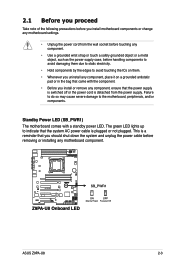
...; Use a grounded wrist strap or touch a safely grounded object or a metal object, such as the power supply case, before removing or installing any motherboard component. ASUS Z9PA-U8 2-3 2.1 Before you proceed Take note of the following precautions before you install motherboard components or change any motherboard settings. • Unplug the power cord from...
...; Use a grounded wrist strap or touch a safely grounded object or a metal object, such as the power supply case, before removing or installing any motherboard component. ASUS Z9PA-U8 2-3 2.1 Before you proceed Take note of the following precautions before you install motherboard components or change any motherboard settings. • Unplug the power cord from...
User Guide
Page 25
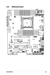
2.2.3 Motherboard layout ASUS Z9PA-U8 2-5
2.2.3 Motherboard layout ASUS Z9PA-U8 2-5
User Guide
Page 27
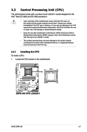
... cap on the LGA2011 socket. • The product warranty does not cover damage to the PnP cap/socket contacts/motherboard components. ASUS Z9PA-U8 2-7 ASUS will shoulder the cost of the motherboard, ensure that the PnP cap is missing, or if you see any damage to the ...resulting from incorrect CPU installation/removal, or misplacement/loss/ incorrect removal of the PnP cap. 2.3.1 Installing the CPU To install a CPU: 1. ASUS will process Return Merchandise Authorization (RMA) requests only if the motherboard comes with a surface mount LGA2011 socket designed for the Intel® Xeon...
... cap on the LGA2011 socket. • The product warranty does not cover damage to the PnP cap/socket contacts/motherboard components. ASUS Z9PA-U8 2-7 ASUS will shoulder the cost of the motherboard, ensure that the PnP cap is missing, or if you see any damage to the ...resulting from incorrect CPU installation/removal, or misplacement/loss/ incorrect removal of the PnP cap. 2.3.1 Installing the CPU To install a CPU: 1. ASUS will process Return Merchandise Authorization (RMA) requests only if the motherboard comes with a surface mount LGA2011 socket designed for the Intel® Xeon...
User Guide
Page 29
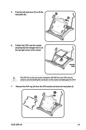
5. Position the CPU over the socket, ensuring that the triangle mark is on the socket and damaging the CPU! 7. DO NOT force the CPU into the socket to lift the load plate (G). I ). F G 6. Triangle mark The CPU fits in only one correct orientation. Remove the PnP cap (H) from the CPU socket and close the load plate (I H ASUS Z9PA-U8 2-9 Push the left load lever (F) to prevent bending the connectors on the top‑right corner of the socket.
5. Position the CPU over the socket, ensuring that the triangle mark is on the socket and damaging the CPU! 7. DO NOT force the CPU into the socket to lift the load plate (G). I ). F G 6. Triangle mark The CPU fits in only one correct orientation. Remove the PnP cap (H) from the CPU socket and close the load plate (I H ASUS Z9PA-U8 2-9 Push the left load lever (F) to prevent bending the connectors on the top‑right corner of the socket.

User Guide
Page 31
... come with , ensuring that the heatsink will be in an even thin layer. The Thermal Interface Material is spread in contact with preapplied thermal paste. ASUS Z9PA-U8 2-11 If so, skip this connector. DO NOT forget to the exposed area of the CPU that it is toxic and inedible. 11. Apply some...
... come with , ensuring that the heatsink will be in an even thin layer. The Thermal Interface Material is spread in contact with preapplied thermal paste. ASUS Z9PA-U8 2-11 If so, skip this connector. DO NOT forget to the exposed area of the CPU that it is toxic and inedible. 11. Apply some...
User Guide
Page 33
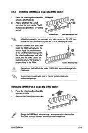
... the DIMM simultaneously until the retaining clip snaps back into place, and the DIMM cannot be pushed in the wrong direction to the DIMM notch. ASUS Z9PA-U8 2-13 Removing a DIMM from the socket. 2 1 Support the DIMM lightly with extra force. Remove the DIMM from a single clip DIMM socket 1. DIMM slot key 1 Unlocked...
... the DIMM simultaneously until the retaining clip snaps back into place, and the DIMM cannot be pushed in the wrong direction to the DIMM notch. ASUS Z9PA-U8 2-13 Removing a DIMM from the socket. 2 1 Support the DIMM lightly with extra force. Remove the DIMM from a single clip DIMM socket 1. DIMM slot key 1 Unlocked...
User Guide
Page 35
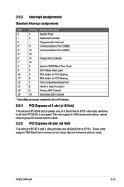
ASUS Z9PA-U8 2-15 Programmable Interrupt 3* 11 Communications Port (COM2) 4* 12 Communications Port (COM1) 5* 13 -- 6 14 Floppy Disk Controller 7* 15 -- 8 3 System CMOS/Real Time Clock 9* 4 ACPI Mode when ...
ASUS Z9PA-U8 2-15 Programmable Interrupt 3* 11 Communications Port (COM2) 4* 12 Communications Port (COM1) 5* 13 -- 6 14 Floppy Disk Controller 7* 15 -- 8 3 System CMOS/Real Time Clock 9* 4 ACPI Mode when ...
User Guide
Page 37
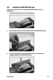
Insert the PIKE RAID card into the PIKE RAID card slot. Ensure that it is completely seated on your motherboard. 1. ASUS Z9PA-U8 2-17 Align the golden fingers of the PIKE RAID card with the PIKE RAID card slot. 3. 2.5.7 Installing an ASUS PIKE RAID card Follow the steps below to install an optional ASUS PIKE RAID card on the PIKE RAID card slot. Locate the PIKE RAID card slot on the motherboard. 2.
Insert the PIKE RAID card into the PIKE RAID card slot. Ensure that it is completely seated on your motherboard. 1. ASUS Z9PA-U8 2-17 Align the golden fingers of the PIKE RAID card with the PIKE RAID card slot. 3. 2.5.7 Installing an ASUS PIKE RAID card Follow the steps below to install an optional ASUS PIKE RAID card on the PIKE RAID card slot. Locate the PIKE RAID card slot on the motherboard. 2.

User Guide
Page 39
... after system initiation finishes. • The heartbeat LED functions only when you install the ASUS ASMB6. • Everytime after the AC power is OFF, ASUS ASMB6 management device starts system initiation for about 30 seconds for about one (1) minute. ASUS Z9PA-U8 2-19 2.6 Onboard LEDs 1. CPU warning LED (ERR_CPU) The CPU warning LEDs light up...
... after system initiation finishes. • The heartbeat LED functions only when you install the ASUS ASMB6. • Everytime after the AC power is OFF, ASUS ASMB6 management device starts system initiation for about 30 seconds for about one (1) minute. ASUS Z9PA-U8 2-19 2.6 Onboard LEDs 1. CPU warning LED (ERR_CPU) The CPU warning LEDs light up...
User Guide
Page 41
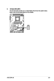
Q-Code LED (LED1) The Q-Code LED provides you a 2-digit display that shows the system status. ASUS Z9PA-U8 2-21 5. Refer to the Q-Code table below for more details.
Q-Code LED (LED1) The Q-Code LED provides you a 2-digit display that shows the system status. ASUS Z9PA-U8 2-21 5. Refer to the Q-Code table below for more details.
User Guide
Page 43
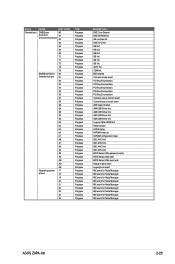
... ME event for Node Manager ME event for Node Manager ME event for Node Manager ME event for Node Manager ME event for Node Manager ASUS Z9PA-U8 2-23
... ME event for Node Manager ME event for Node Manager ME event for Node Manager ME event for Node Manager ME event for Node Manager ASUS Z9PA-U8 2-23
User Guide
Page 45
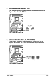
Set to pins 1-2 to enable or disable the onboard VGA controller. ASUS Z9PA-U8 2-25 VGA controller setting (3-pin VGA_SW1) This jumper allows you to activate the VGA feature. 3. Set to pins 1-2 to enable or disable the onboard Intel® 82574L Gigabit LAN controllers. 2. LAN controller setting (3-pin LAN_SW1/ LAN_SW2) These jumpers allow you to activate the Gigabit LAN feature.
Set to pins 1-2 to enable or disable the onboard VGA controller. ASUS Z9PA-U8 2-25 VGA controller setting (3-pin VGA_SW1) This jumper allows you to activate the VGA feature. 3. Set to pins 1-2 to enable or disable the onboard Intel® 82574L Gigabit LAN controllers. 2. LAN controller setting (3-pin LAN_SW1/ LAN_SW2) These jumpers allow you to activate the Gigabit LAN feature.
User Guide
Page 47
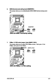
PMBus 1.2 PSU select jumper (3-pin SMART_PSU1) This jumper allows you to pins 2-3 for Others. 6. ASUS Z9PA-U8 2-27 DDR3 thermal event setting (3-pin DIMMTRIP1) This jumper allows you to select PSU PMBus version, Set to pins 1-2 for PMBus, set to enable/disable DDR3 DIMM thermal sensing event pin. 7.
PMBus 1.2 PSU select jumper (3-pin SMART_PSU1) This jumper allows you to pins 2-3 for Others. 6. ASUS Z9PA-U8 2-27 DDR3 thermal event setting (3-pin DIMMTRIP1) This jumper allows you to select PSU PMBus version, Set to pins 1-2 for PMBus, set to enable/disable DDR3 DIMM thermal sensing event pin. 7.
User Guide
Page 49
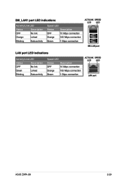
DM_LAN1 port LED indications Activity/Link LED Status Description OFF No link Orange Linked Blinking Data activity Speed LED Status Description OFF 10 Mbps connection Orange 100 Mbps connection Green 1 Gbps connection ACT/LINK SPEED LED LED DM LAN port LAN port LED indications Activity/Link LED Status Description OFF No link Green Linked Blinking Data activity Speed LED Status Description OFF 10 Mbps connection Orange 100 Mbps connection Green 1 Gbps connection ACT/LINK SPEED LED LED LAN port ASUS Z9PA-U8 2-29
DM_LAN1 port LED indications Activity/Link LED Status Description OFF No link Orange Linked Blinking Data activity Speed LED Status Description OFF 10 Mbps connection Orange 100 Mbps connection Green 1 Gbps connection ACT/LINK SPEED LED LED DM LAN port LAN port LED indications Activity/Link LED Status Description OFF No link Green Linked Blinking Data activity Speed LED Status Description OFF 10 Mbps connection Orange 100 Mbps connection Green 1 Gbps connection ACT/LINK SPEED LED LED LAN port ASUS Z9PA-U8 2-29

User Guide
Page 51
... 6Gb/s of SAS hard disks installed. 3. 2. Hard disk activity LED connector (4-pin HDLED1) This LED connector is for SAS hard disk drives that allows up . ASUS Z9PA-U8 2-31
... 6Gb/s of SAS hard disks installed. 3. 2. Hard disk activity LED connector (4-pin HDLED1) This LED connector is for SAS hard disk drives that allows up . ASUS Z9PA-U8 2-31
User Guide
Page 53
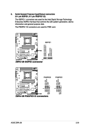
The PSGPIO 1/2 connectors are used for the Intel Rapid Storage Technology Enterprise SGPIO interface that controls the LED pattern generation, device information and general purpose data. ASUS Z9PA-U8 2-33 Serial General Purpose Input/Output connectors (6-1 pin SGPIO1, 8-1 pin PSGPIO 1/2) The SGPIO 1 connectors are used for PIKE card. 6.
The PSGPIO 1/2 connectors are used for the Intel Rapid Storage Technology Enterprise SGPIO interface that controls the LED pattern generation, device information and general purpose data. ASUS Z9PA-U8 2-33 Serial General Purpose Input/Output connectors (6-1 pin SGPIO1, 8-1 pin PSGPIO 1/2) The SGPIO 1 connectors are used for PIKE card. 6.

User Guide
Page 55
The power supply plugs are for an EATX power supply plugs. ASUS Z9PA-U8 2-35 9. EATX power connectors (24-pin EATXPWR1, 8-pin EATX12V1) These connectors are designed to connect the 24+8-pin power plugs; Find the proper orientation and ...
The power supply plugs are for an EATX power supply plugs. ASUS Z9PA-U8 2-35 9. EATX power connectors (24-pin EATXPWR1, 8-pin EATX12V1) These connectors are designed to connect the 24+8-pin power plugs; Find the proper orientation and ...


