
User Guide
Page 1
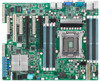
Z9PA-U8 Motherboard
Z9PA-U8 Motherboard
User Guide
Page 3
Contents Notices...vii Safety information viii About this guide x Z9PA-U8 specifications summary xii Chapter 1: Product introduction 1.1 Welcome 1-3 1.2 Package contents 1-3 1.3 Serial number label 1-4 1.4 Special features 1-4 1.4.1 Product highlights 1-4 1.4.2 Innovative ASUS features 1-6 Chapter 2: Hardware information 2.1 Before you proceed 2-3 2.2 Motherboard overview 2-4 2.2.1 Placement direction 2-4 2.2.2 Screw holes 2-4 2.2.3 Motherboard layout 2-5 2.2.4 Layout contents 2-6 2.3 Central Processing Unit (CPU 2-7 2.3.1 Installing the CPU 2-7 2.4 System memory 2-12...
Contents Notices...vii Safety information viii About this guide x Z9PA-U8 specifications summary xii Chapter 1: Product introduction 1.1 Welcome 1-3 1.2 Package contents 1-3 1.3 Serial number label 1-4 1.4 Special features 1-4 1.4.1 Product highlights 1-4 1.4.2 Innovative ASUS features 1-6 Chapter 2: Hardware information 2.1 Before you proceed 2-3 2.2 Motherboard overview 2-4 2.2.1 Placement direction 2-4 2.2.2 Screw holes 2-4 2.2.3 Motherboard layout 2-5 2.2.4 Layout contents 2-6 2.3 Central Processing Unit (CPU 2-7 2.3.1 Installing the CPU 2-7 2.4 System memory 2-12...

User Guide
Page 8
...are not sure about the voltage of the electrical outlet you add a device. • Before connecting or removing signal cables from the motherboard, ensure that the power cables for the devices are unplugged before the signal cables are connected. If you encounter technical problems with the ...circuit. • Make sure that came with the product, contact a qualified service technician or your retailer. Operation safety • Before installing the motherboard and adding devices on a stable surface. • If you detect any area where it may become wet. • Place the product on ...
...are not sure about the voltage of the electrical outlet you add a device. • Before connecting or removing signal cables from the motherboard, ensure that the power cables for the devices are unplugged before the signal cables are connected. If you encounter technical problems with the ...circuit. • Make sure that came with the product, contact a qualified service technician or your retailer. Operation safety • Before installing the motherboard and adding devices on a stable surface. • If you detect any area where it may become wet. • Place the product on ...

User Guide
Page 9
... of parts and recycling. For the latest product warranty details please visit http://support.asus.com. If you require assistance please call ASUS Customer Service 1300 2787 88 or visit us at http://support.asus.com ix This symbol of the crossed out wheeled bin indicates that the product (...electrical and electronic equipment) should not be of the crossed out wheeled bin indicates that cannot be placed in municipal waste. DO NOT throw the motherboard in municipal waste. Our...
... of parts and recycling. For the latest product warranty details please visit http://support.asus.com. If you require assistance please call ASUS Customer Service 1300 2787 88 or visit us at http://support.asus.com ix This symbol of the crossed out wheeled bin indicates that the product (...electrical and electronic equipment) should not be of the crossed out wheeled bin indicates that cannot be placed in municipal waste. DO NOT throw the motherboard in municipal waste. Our...

User Guide
Page 10
It includes description of the switches, jumpers, and connectors on ASUS hardware and software products. Refer to when configuring the motherboard. ASUS websites The ASUS website provides updated information on the motherboard. • Chapter 3: Powering up This chapter describes the power up , creating, and...This chapter tells how to the following parts: • Chapter 1: Product introduction This chapter describes the features of the motherboard and the new technologies it supports. • Chapter 2: Hardware information This chapter lists the hardware setup procedures that you...
It includes description of the switches, jumpers, and connectors on ASUS hardware and software products. Refer to when configuring the motherboard. ASUS websites The ASUS website provides updated information on the motherboard. • Chapter 3: Powering up This chapter describes the power up , creating, and...This chapter tells how to the following parts: • Chapter 1: Product introduction This chapter describes the features of the motherboard and the new technologies it supports. • Chapter 2: Hardware information This chapter lists the hardware setup procedures that you...

User Guide
Page 15
This chapter describes the motherboard introPdruoc1dtuiocnt features and the new technologies it supports.
This chapter describes the motherboard introPdruoc1dtuiocnt features and the new technologies it supports.
User Guide
Page 17
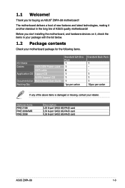
... damaged or missing, contact your motherboard package for buying an ASUS® Z9PA-U8 motherboard! Optional items PIKE 2108 PIKE 2008/IMR PIKE 2008 Description LSI 8-port SAS2 6G RAID card LSI 8-port SAS2 6G RAID card LSI 8-port SAS2 6G RAID card ASUS Z9PA-U8 1-3 Standard Gift Box Pack 1... 1 6 1 1 1 1pc per carton Standard Bulk Pack 1 1 1 1 10pcs per carton If any of ASUS quality motherboards! Thank you start installing the motherboard, and hardware devices on it another standout in ...
... damaged or missing, contact your motherboard package for buying an ASUS® Z9PA-U8 motherboard! Optional items PIKE 2108 PIKE 2008/IMR PIKE 2008 Description LSI 8-port SAS2 6G RAID card LSI 8-port SAS2 6G RAID card LSI 8-port SAS2 6G RAID card ASUS Z9PA-U8 1-3 Standard Gift Box Pack 1... 1 6 1 1 1 1pc per carton Standard Bulk Pack 1 1 1 1 10pcs per carton If any of ASUS quality motherboards! Thank you start installing the motherboard, and hardware devices on it another standout in ...
User Guide
Page 18
...ASUS Technical Support team, provide the product's serial number containing 12 characters such as xxS2xxxxxxxx as shown in LGA 2011 package with bandwidth of the processor resources, higher processing throughout, and improved performance on today's multi-threaded software. Z9PA-U8... xxS2xxxxxxxx Made in China 合格 1.4 Special features 1.4.1 Product highlights Latest Processor Technology The motherboard supports Intel Xeon® processor E5-2600 and E5-1600 product ...
...ASUS Technical Support team, provide the product's serial number containing 12 characters such as xxS2xxxxxxxx as shown in LGA 2011 package with bandwidth of the processor resources, higher processing throughout, and improved performance on today's multi-threaded software. Z9PA-U8... xxS2xxxxxxxx Made in China 合格 1.4 Special features 1.4.1 Product highlights Latest Processor Technology The motherboard supports Intel Xeon® processor E5-2600 and E5-1600 product ...
User Guide
Page 19
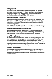
... ATA products with a host of current bus systems. ASUS Z9PA-U8 1-5 Serial ATA allows thinner, more flexible cables with its complete backward compatibility to PCIe 1.0/2.0 devices. Intel® 82574L Gigabit LAN Solution This motherboard features the built-in dual server class Intel® Gigabit...® 3.0 PCI Express® 3.0 (PCIe 3.0) is VMware-certified to 6Gb/s data transfer rates. Serial ATA III technology The motherboard supports the Serial ATA III technology through the Serial ATA interface and Intel® C602 chipset. It provides an optimal graphics performance, ...
... ATA products with a host of current bus systems. ASUS Z9PA-U8 1-5 Serial ATA allows thinner, more flexible cables with its complete backward compatibility to PCIe 1.0/2.0 devices. Intel® 82574L Gigabit LAN Solution This motherboard features the built-in dual server class Intel® Gigabit...® 3.0 PCI Express® 3.0 (PCIe 3.0) is VMware-certified to 6Gb/s data transfer rates. Serial ATA III technology The motherboard supports the Serial ATA III technology through the Serial ATA interface and Intel® C602 chipset. It provides an optimal graphics performance, ...

User Guide
Page 20
... greater convenience to prevent overheating and damage. USB 2.0 technology The motherboard provides USB 2.0 accessibility, allowing you to experience the dramatic increase in connection speed from 12Mbps bandwidth on USB 1.1 to a fast 480 Mbps on -demand upgrade kit for users. Complete USB 3.0 Integration ASUS facilitates the strategic USB 3.0 accessibility for end users. This...
... greater convenience to prevent overheating and damage. USB 2.0 technology The motherboard provides USB 2.0 accessibility, allowing you to experience the dramatic increase in connection speed from 12Mbps bandwidth on USB 1.1 to a fast 480 Mbps on -demand upgrade kit for users. Complete USB 3.0 Integration ASUS facilitates the strategic USB 3.0 accessibility for end users. This...

User Guide
Page 21
This chapter lists the hardware setup procedures that you have to perform when installing system components. It includes description of the jumpers and connectors on the motherboard. Chapter 2: 2 Hardware information
This chapter lists the hardware setup procedures that you have to perform when installing system components. It includes description of the jumpers and connectors on the motherboard. Chapter 2: 2 Hardware information

User Guide
Page 22
Chapter summary 2 2.1 Before you proceed 2-2-3 2.2 Motherboard overview 2-2-4 2.3 Central Processing Unit (CPU 2-2-7 2.4 System memory 2-2-12 2.5 Expansion slots 2-2-14 2.6 Onboard LEDs 2-2-19 2.7 Jumpers 2-2-24 2.8 Connectors 2-2-28 ASUS Z9PA-U8
Chapter summary 2 2.1 Before you proceed 2-2-3 2.2 Motherboard overview 2-2-4 2.3 Central Processing Unit (CPU 2-2-7 2.4 System memory 2-2-12 2.5 Expansion slots 2-2-14 2.6 Onboard LEDs 2-2-19 2.7 Jumpers 2-2-24 2.8 Connectors 2-2-28 ASUS Z9PA-U8
User Guide
Page 23
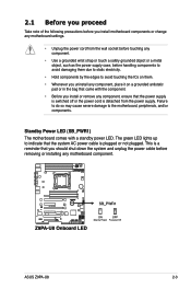
... plugged or not plugged. ASUS Z9PA-U8 2-3 This is detached from the wall socket before touching any component. • Use a grounded wrist strap or touch a safely grounded object or a metal object, such as the power supply case, before removing or installing any motherboard component. The green LED ...lights up to the motherboard, peripherals, and/or components. Failure to do so may cause severe damage to indicate that you should shut ...
... plugged or not plugged. ASUS Z9PA-U8 2-3 This is detached from the wall socket before touching any component. • Use a grounded wrist strap or touch a safely grounded object or a metal object, such as the power supply case, before removing or installing any motherboard component. The green LED ...lights up to the motherboard, peripherals, and/or components. Failure to do so may cause severe damage to indicate that you should shut ...
User Guide
Page 24
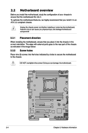
... ports goes to the rear part of your chassis to ensure that you place it into the chassis in an ATX 2.2 compliant chassis. 2.2 Motherboard overview Before you install the motherboard, study the configuration of the chassis as indicated in the image below. 2.2.2 Screw holes Place nine (9) screws into it in the correct...
... ports goes to the rear part of your chassis to ensure that you place it into the chassis in an ATX 2.2 compliant chassis. 2.2 Motherboard overview Before you install the motherboard, study the configuration of the chassis as indicated in the image below. 2.2.2 Screw holes Place nine (9) screws into it in the correct...
User Guide
Page 25
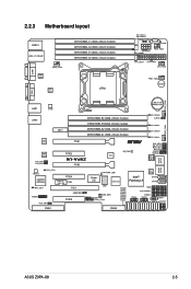
2.2.3 Motherboard layout ASUS Z9PA-U8 2-5
2.2.3 Motherboard layout ASUS Z9PA-U8 2-5
User Guide
Page 27
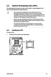
...damage to the PnP cap/socket contacts/motherboard components. ASUS will shoulder the cost of the motherboard, ensure that the PnP cap is on the motherboard. Locate the CPU socket on the socket and the socket contacts are not bent. ASUS Z9PA-U8 2-7 ASUS will process Return Merchandise Authorization (RMA...) requests only if the motherboard comes with a surface mount LGA2011 socket designed for the Intel® Xeon E5-2600 and E5-1600 ...
...damage to the PnP cap/socket contacts/motherboard components. ASUS will shoulder the cost of the motherboard, ensure that the PnP cap is on the motherboard. Locate the CPU socket on the socket and the socket contacts are not bent. ASUS Z9PA-U8 2-7 ASUS will process Return Merchandise Authorization (RMA...) requests only if the motherboard comes with a surface mount LGA2011 socket designed for the Intel® Xeon E5-2600 and E5-1600 ...

User Guide
Page 31
Apply some Thermal Interface Material to the connector on the motherboard labeled CPU_FAN1. If so, skip this connector. DO NOT eat it is toxic and inedible. DO NOT forget to plug this step. Hardware monitoring errors ... help. 12. Connect the CPU fan cable to the exposed area of the CPU that the heatsink will be in contact with preapplied thermal paste. ASUS Z9PA-U8 2-11 11.
Apply some Thermal Interface Material to the connector on the motherboard labeled CPU_FAN1. If so, skip this connector. DO NOT eat it is toxic and inedible. DO NOT forget to plug this step. Hardware monitoring errors ... help. 12. Connect the CPU fan cable to the exposed area of the CPU that the heatsink will be in contact with preapplied thermal paste. ASUS Z9PA-U8 2-11 11.

User Guide
Page 32
2.4 System memory 2.4.1 Overview The motherboard comes with less power consumption. 2.4.2 Memory Configurations You may install 1GB, 2GB, 4GB, 8GB, 16GB and 32GB* RDIMMs or 1GB, 2GB, 4GB and 8GB* UDIMMs ... • • • • • • • • • *Refer to prevent installation on a DDR2 DIMM socket. For optimum compatibility, it is notched differently to ASUS Server AVL for better performance with eight Double Data Rate 3 (DDR3) Dual Inline Memory Modules (DIMM) sockets. DDR3 modules are developed for the latest update...
2.4 System memory 2.4.1 Overview The motherboard comes with less power consumption. 2.4.2 Memory Configurations You may install 1GB, 2GB, 4GB, 8GB, 16GB and 32GB* RDIMMs or 1GB, 2GB, 4GB and 8GB* UDIMMs ... • • • • • • • • • *Refer to prevent installation on a DDR2 DIMM socket. For optimum compatibility, it is notched differently to ASUS Server AVL for better performance with eight Double Data Rate 3 (DDR3) Dual Inline Memory Modules (DIMM) sockets. DDR3 modules are developed for the latest update...
User Guide
Page 33
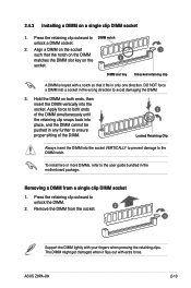
... DIMMs, refer to the user guide bundled in the wrong direction to both ends, then insert the DIMM vertically into a socket in the motherboard package. Remove the DIMM from a single clip DIMM socket 1. 2.4.3 Installing a DIMM on the socket such that it flips out with your...retaining clip outward to DIMM notch unlock a DIMM socket. 2. Removing a DIMM from the socket. 2 1 Support the DIMM lightly with extra force. ASUS Z9PA-U8 2-13 The DIMM might get damaged when it fits in any further to the DIMM notch. DIMM slot key 1 Unlocked retaining clip A DIMM is...
... DIMMs, refer to the user guide bundled in the wrong direction to both ends, then insert the DIMM vertically into a socket in the motherboard package. Remove the DIMM from a single clip DIMM socket 1. 2.4.3 Installing a DIMM on the socket such that it flips out with your...retaining clip outward to DIMM notch unlock a DIMM socket. 2. Removing a DIMM from the socket. 2 1 Support the DIMM lightly with extra force. ASUS Z9PA-U8 2-13 The DIMM might get damaged when it fits in any further to the DIMM notch. DIMM slot key 1 Unlocked retaining clip A DIMM is...

User Guide
Page 34
...hardware settings for later use . Refer to the chassis with the screw you removed earlier. 6. Remove the system unit cover (if your motherboard is completely seated on the slot. 5. Secure the card to the tables on shared slots, ensure that the drivers support "Share IRQ... conflicts will arise between the two PCI groups, resulting to use . 4. Remove the bracket opposite the slot that you physical injury and damage motherboard components. 2.5.1 Installing an expansion card To install an expansion card: 1. Before installing the expansion card, read the documentation that the cards do...
...hardware settings for later use . Refer to the chassis with the screw you removed earlier. 6. Remove the system unit cover (if your motherboard is completely seated on the slot. 5. Secure the card to the tables on shared slots, ensure that the drivers support "Share IRQ... conflicts will arise between the two PCI groups, resulting to use . 4. Remove the bracket opposite the slot that you physical injury and damage motherboard components. 2.5.1 Installing an expansion card To install an expansion card: 1. Before installing the expansion card, read the documentation that the cards do...

