User Guide
Page 17
...PIKE 2008/IMR PIKE 2008 Description LSI 8-port SAS2 6G RAID card LSI 8-port SAS2 6G RAID card LSI 8-port SAS2 6G RAID card ASUS Z9NR-D12 1-3 Thank you start installing the motherboard, and hardware devices on it another standout in your package with the list below. 1.2 Package contents... any of new features and latest technologies, making it , check the items in the long line of ASUS quality motherboards! 1.1 Welcome! Before you for the following items. Z9NR-D12 ASMB6-iKVM module Cables SATA DOM cable SATA cable Support CD Application CD ASWM Enterprise SDVD ASMB6-iKVM SDVD...
...PIKE 2008/IMR PIKE 2008 Description LSI 8-port SAS2 6G RAID card LSI 8-port SAS2 6G RAID card LSI 8-port SAS2 6G RAID card ASUS Z9NR-D12 1-3 Thank you start installing the motherboard, and hardware devices on it another standout in your package with the list below. 1.2 Package contents... any of new features and latest technologies, making it , check the items in the long line of ASUS quality motherboards! 1.1 Welcome! Before you for the following items. Z9NR-D12 ASMB6-iKVM module Cables SATA DOM cable SATA cable Support CD Application CD ASWM Enterprise SDVD ASMB6-iKVM SDVD...
User Guide
Page 19
... Hot Swap. The Serial ATA II specification provides twice the bandwidth of the current Serial ATA products with a host of current bus systems. ASUS Z9NR-D12 1-5 DDR3 memory support The Z9NR-D12 supports DDR3 memory that features data transfer rates of 1600/1333/1066 MHz to meet the higher bandwidth requirements of PCIe 2.0. Serial ATA...
... Hot Swap. The Serial ATA II specification provides twice the bandwidth of the current Serial ATA products with a host of current bus systems. ASUS Z9NR-D12 1-5 DDR3 memory support The Z9NR-D12 supports DDR3 memory that features data transfer rates of 1600/1333/1066 MHz to meet the higher bandwidth requirements of PCIe 2.0. Serial ATA...
User Guide
Page 22
Chapter summary 2 2.1 Before you proceed 2-3 2.2 Motherboard overview 2-4 2.3 Central Processing Unit (CPU 2-8 2.4 System memory 2-12 2.5 Expansion slots 2-15 2.6 Onboard LEDs 2-21 2.7 Jumpers 2-26 2.8 Connectors 2-30 ASUS Z9NR-D12
Chapter summary 2 2.1 Before you proceed 2-3 2.2 Motherboard overview 2-4 2.3 Central Processing Unit (CPU 2-8 2.4 System memory 2-12 2.5 Expansion slots 2-15 2.6 Onboard LEDs 2-21 2.7 Jumpers 2-26 2.8 Connectors 2-30 ASUS Z9NR-D12
User Guide
Page 23
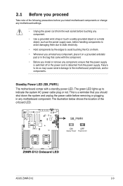
... the location of the following precautions before you install motherboard components or change any motherboard settings. • Unplug the power cord from the power supply. ASUS Z9NR-D12 2-3 The green LED lights up to the motherboard, peripherals, and/or components. 2.1 Before you proceed Take note of the onboard LED.
... the location of the following precautions before you install motherboard components or change any motherboard settings. • Unplug the power cord from the power supply. ASUS Z9NR-D12 2-3 The green LED lights up to the motherboard, peripherals, and/or components. 2.1 Before you proceed Take note of the onboard LED.
User Guide
Page 25
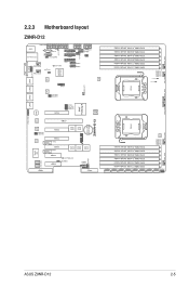
2.2.3 Motherboard layout Z9NR-D12 ASUS Z9NR-D12 2-5
2.2.3 Motherboard layout Z9NR-D12 ASUS Z9NR-D12 2-5
User Guide
Page 29
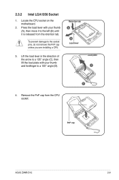
Press the load lever with your thumb (A), then move it to the left (B) until it is released from the CPU socket. Remove the PnP cap from the retention tab. Lift the load lever in the direction of the arrow to a 135° angle (C), then lift the load plate with your thumb and forefinger to the socket pins, do not remove the PnP cap unless you are installing a CPU. 3. PnP cap ASUS Z9NR-D12 2-9 Locate the CPU socket on the motherboard. 2. Retention tab A B Load lever Load plate D C 4. 2.3.2 Intel LGA1356 Socket 1. To prevent damage to a 100° angle (D).
Press the load lever with your thumb (A), then move it to the left (B) until it is released from the CPU socket. Remove the PnP cap from the retention tab. Lift the load lever in the direction of the arrow to a 135° angle (C), then lift the load plate with your thumb and forefinger to the socket pins, do not remove the PnP cap unless you are installing a CPU. 3. PnP cap ASUS Z9NR-D12 2-9 Locate the CPU socket on the motherboard. 2. Retention tab A B Load lever Load plate D C 4. 2.3.2 Intel LGA1356 Socket 1. To prevent damage to a 100° angle (D).
User Guide
Page 31
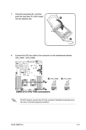
ASUS Z9NR-D12 2-11 DO NOT forget to plug this connector. Hardware monitoring errors can occur if you fail to connect the CPU fan connector! Close the load plate (E), and then push the load lever (F) until it snaps into the retention tab. 7. E F 8. Connect the CPU fan cable to the connector on the motherboard labeled CPU_FAN1 / CPU_FAN2.
ASUS Z9NR-D12 2-11 DO NOT forget to plug this connector. Hardware monitoring errors can occur if you fail to connect the CPU fan connector! Close the load plate (E), and then push the load lever (F) until it snaps into the retention tab. 7. E F 8. Connect the CPU fan cable to the connector on the motherboard labeled CPU_FAN1 / CPU_FAN2.
User Guide
Page 35
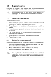
... the software settings. 1. 2.5 Expansion slots In the future, you removed earlier. 6. Assign an IRQ to unplug the power cord before adding or removing expansion cards. ASUS Z9NR-D12 2-15 Before installing the expansion card, read the documentation that they support. Keep the screw for information on the slot. 5. Refer to use . 4.
... the software settings. 1. 2.5 Expansion slots In the future, you removed earlier. 6. Assign an IRQ to unplug the power cord before adding or removing expansion cards. ASUS Z9NR-D12 2-15 Before installing the expansion card, read the documentation that they support. Keep the screw for information on the slot. 5. Refer to use . 4.
User Guide
Page 37
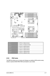
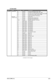
PCIE 1 PCIE 2 PCIE 3 PCIE 4 PCIE 5 PCIE 6 PCIE 7 1 x PCI-E x 8 (Gen3 x4 link) 1 x PCI-E x 16 (Gen3 x16 link) 1 x PCI-E x 8 (Gen3 x8 link) 1 x PCI-E x 8 (Gen3 x8 link) 1 x PCI-E x 8 (Gen3 x8 link) 1 x PCI-E x 4 (Gen3 x2 link) 1 x PCI-E x 4 (Gen3 x1 link) 2.5.9 PIKE slots The PIKE slot allows you to choose and change your needs. Install an optional ASUS PIKE RAID card based on your preferred SAS solution easily. ASUS Z9NR-D12 2-17
PCIE 1 PCIE 2 PCIE 3 PCIE 4 PCIE 5 PCIE 6 PCIE 7 1 x PCI-E x 8 (Gen3 x4 link) 1 x PCI-E x 16 (Gen3 x16 link) 1 x PCI-E x 8 (Gen3 x8 link) 1 x PCI-E x 8 (Gen3 x8 link) 1 x PCI-E x 8 (Gen3 x8 link) 1 x PCI-E x 4 (Gen3 x2 link) 1 x PCI-E x 4 (Gen3 x1 link) 2.5.9 PIKE slots The PIKE slot allows you to choose and change your needs. Install an optional ASUS PIKE RAID card based on your preferred SAS solution easily. ASUS Z9NR-D12 2-17
User Guide
Page 39
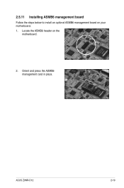
ASUS Z9NR-D12 2-19 Locate the ASMB6 header on your motherboard. 1. 2.5.11 Installing ASMB6 management board Follow the steps below to install an optional ASMB6 management board on the motherboard. 2. Orient and press the ASMB6 management card in place.
ASUS Z9NR-D12 2-19 Locate the ASMB6 header on your motherboard. 1. 2.5.11 Installing ASMB6 management board Follow the steps below to install an optional ASMB6 management board on the motherboard. 2. Orient and press the ASMB6 management card in place.
User Guide
Page 41
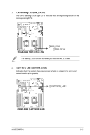
ASUS Z9NR-D12 2-21 The warning LEDs function only when you install the ASUS ASMB6. 4. CATT Error LED (CATTERR_LED1) Indicates that an impending failure of the corresponding CPU. CPU warning LED (ERR_CPU1/2) The CPU warning LEDs light up to indicate that the system has experienced a fatal or catastrophic error and cannot continue to operate. 3.
ASUS Z9NR-D12 2-21 The warning LEDs function only when you install the ASUS ASMB6. 4. CATT Error LED (CATTERR_LED1) Indicates that an impending failure of the corresponding CPU. CPU warning LED (ERR_CPU1/2) The CPU warning LEDs light up to indicate that the system has experienced a fatal or catastrophic error and cannot continue to operate. 3.
User Guide
Page 43
Memory Init. Memory Init. Memory Init. CPU Init. DXE Initial Program Load(IPL) (continued on the next page) ASUS Z9NR-D12 2-23 Memory Init. Memory Init. Memory Init. CPU Init. QPI initialization QPI initialization QPI initialization QPI initialization QPI initialization QPI initialization QPI initialization QPI initialization ...
Memory Init. Memory Init. Memory Init. CPU Init. DXE Initial Program Load(IPL) (continued on the next page) ASUS Z9NR-D12 2-23 Memory Init. Memory Init. Memory Init. CPU Init. QPI initialization QPI initialization QPI initialization QPI initialization QPI initialization QPI initialization QPI initialization QPI initialization ...
User Guide
Page 45
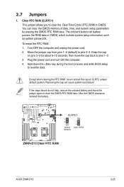
... battery. Move the jumper cap from pins 1-2 (default) to clear the CMOS RTC RAM data. Plug the power cord and turn ON the computer. 4. 2.7 Jumpers 1. ASUS Z9NR-D12 2-25 Clear RTC RAM (CLRTC1) This jumper allows you to re-enter data. The onboard button cell battery powers the RAM data in CMOS. Hold...
... battery. Move the jumper cap from pins 1-2 (default) to clear the CMOS RTC RAM data. Plug the power cord and turn ON the computer. 4. 2.7 Jumpers 1. ASUS Z9NR-D12 2-25 Clear RTC RAM (CLRTC1) This jumper allows you to re-enter data. The onboard button cell battery powers the RAM data in CMOS. Hold...
User Guide
Page 47
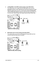
...) This jumper allows you to select the PCH SATA RAID mode to force Intel Management Engine (ME) boot from recovery mode when ME become corrupted. ASUS Z9NR-D12 2-27 Place the jumper caps over pins 1-2 if you to use the Intel® Rapid Storage Technology Enterprise Option ROM Utility. 5. 4.
...) This jumper allows you to select the PCH SATA RAID mode to force Intel Management Engine (ME) boot from recovery mode when ME become corrupted. ASUS Z9NR-D12 2-27 Place the jumper caps over pins 1-2 if you to use the Intel® Rapid Storage Technology Enterprise Option ROM Utility. 5. 4.
User Guide
Page 49
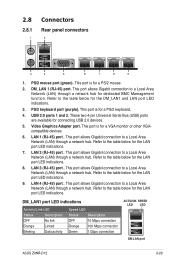
... Data activity Speed LED Status Description OFF 10 Mbps connection Orange 100 Mbps connection Green 1 Gbps connection ACT/LINK SPEED LED LED DM LAN port ASUS Z9NR-D12 2-29 USB 2.0 ports 1 and 2. LAN 1 (RJ-45) port . Video Graphics Adapter port. This port allows Gigabit connection to a Local Area Network (LAN) through a network hub...
... Data activity Speed LED Status Description OFF 10 Mbps connection Orange 100 Mbps connection Green 1 Gbps connection ACT/LINK SPEED LED LED DM LAN port ASUS Z9NR-D12 2-29 USB 2.0 ports 1 and 2. LAN 1 (RJ-45) port . Video Graphics Adapter port. This port allows Gigabit connection to a Local Area Network (LAN) through a network hub...
User Guide
Page 51
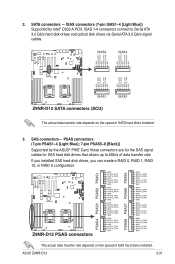
... a RAID 0, RAID 1, RAID 10, or RAID 5 configuration. The actual data transfer rate depends on the speed of data transfer rate. ASUS Z9NR-D12 2-31 ISAS connectors (7-pin ISAS1-4 [Light Blue]) Supported by the ASUS® PIKE Card, these connectors are for the SAS signal cables for SAS hard disk drives that allows up to...
... a RAID 0, RAID 1, RAID 10, or RAID 5 configuration. The actual data transfer rate depends on the speed of data transfer rate. ASUS Z9NR-D12 2-31 ISAS connectors (7-pin ISAS1-4 [Light Blue]) Supported by the ASUS® PIKE Card, these connectors are for the SAS signal cables for SAS hard disk drives that allows up to...
User Guide
Page 53
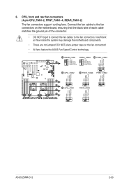
...! • All fans feature the ASUS Fan Speed Control technology. Connect the fan cables to the fan connectors. Insufficient air flow inside the system may damage the motherboard components. • These are not jumpers! 6. CPU, front and rear fan connectors (4-pin CPU_FAN1-2, FRNT_FAN1-4, REAR_FAN1-2) The fan connectors support cooling fans. ASUS Z9NR-D12 2-33
...! • All fans feature the ASUS Fan Speed Control technology. Connect the fan cables to the fan connectors. Insufficient air flow inside the system may damage the motherboard components. • These are not jumpers! 6. CPU, front and rear fan connectors (4-pin CPU_FAN1-2, FRNT_FAN1-4, REAR_FAN1-2) The fan connectors support cooling fans. ASUS Z9NR-D12 2-33
User Guide
Page 55
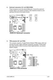
ASUS Z9NR-D12 2-35 TPM connector (20-1 pin TPM1) This connector supports a Trusted Platform Module (TPM) system, which can securely store keys, digital certificates, passwords, and data. Serial port connectors (10-1 pin COM1/COM2) These connectors are for the serial (COM) ports. A TPM system also helps enhance network security, protects digital identities, and ensures platform integrity. 8. Connect the serial port module cable to one of these connectors, then install the module to a slot opening at the back of the system chassis. 9.
ASUS Z9NR-D12 2-35 TPM connector (20-1 pin TPM1) This connector supports a Trusted Platform Module (TPM) system, which can securely store keys, digital certificates, passwords, and data. Serial port connectors (10-1 pin COM1/COM2) These connectors are for the serial (COM) ports. A TPM system also helps enhance network security, protects digital identities, and ensures platform integrity. 8. Connect the serial port module cable to one of these connectors, then install the module to a slot opening at the back of the system chassis. 9.
User Guide
Page 57
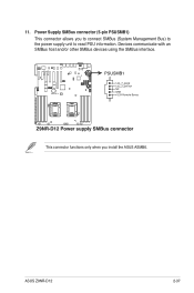
This connector functions only when you to connect SMBus (System Management Bus) to the power supply unit to read PSU information. Devices communicate with an SMBus host and/or other SMBus devices using the SMBus interface. 11. ASUS Z9NR-D12 2-37 Power Supply SMBus connector (5-pin PSUSMB1) This connector allows you install the ASUS ASMB6.
This connector functions only when you to connect SMBus (System Management Bus) to the power supply unit to read PSU information. Devices communicate with an SMBus host and/or other SMBus devices using the SMBus interface. 11. ASUS Z9NR-D12 2-37 Power Supply SMBus connector (5-pin PSUSMB1) This connector allows you install the ASUS ASMB6.
User Guide
Page 59
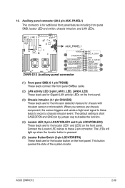
... panel connector (20-2 pin AUX_PANEL1) This connector is pressed. (5) Locator Button/Swich (2-pin LOCATORBTN) These leads are for the locator button on the front panel. ASUS Z9NR-D12 2-39 The LEDs will light up when the Locator button is for additional front panel features including front panel SMB, locator LED and switch, chassis...
... panel connector (20-2 pin AUX_PANEL1) This connector is pressed. (5) Locator Button/Swich (2-pin LOCATORBTN) These leads are for the locator button on the front panel. ASUS Z9NR-D12 2-39 The LEDs will light up when the Locator button is for additional front panel features including front panel SMB, locator LED and switch, chassis...


