
User Guide
Page 3
... Safety information...vi About this guide...vii Z97-WS specifications summary ix Package contents...xv Installation tools and components xvi Chapter 1: Product Introduction 1.1 Special features 1-1 1.1.1 Product highlights 1-1 1.1.2 ASUS-exclusive workstation features 1-2 1.1.3 Other special ...2-6 2.1.5 ATX Power connection 2-7 2.1.6 SATA device connection 2-8 2.1.7 Front I/O Connector 2-9 2.1.8 Expansion Card installation 2-10 2.2 BIOS update utility 2-11 2.3 Motherboard rear and audio connections 2-13 2.3.1 Rear I/O connection 2-13 2.3.2 Audio I/O connections 2-15...
... Safety information...vi About this guide...vii Z97-WS specifications summary ix Package contents...xv Installation tools and components xvi Chapter 1: Product Introduction 1.1 Special features 1-1 1.1.1 Product highlights 1-1 1.1.2 ASUS-exclusive workstation features 1-2 1.1.3 Other special ...2-6 2.1.5 ATX Power connection 2-7 2.1.6 SATA device connection 2-8 2.1.7 Front I/O Connector 2-9 2.1.8 Expansion Card installation 2-10 2.2 BIOS update utility 2-11 2.3 Motherboard rear and audio connections 2-13 2.3.1 Rear I/O connection 2-13 2.3.2 Audio I/O connections 2-15...
User Guide
Page 4
...Updating BIOS 3-60 3.11.1 EZ Update 3-60 3.11.2 ASUS EZ Flash 2 3-61 3.11.3 ASUS CrashFree BIOS 3 3-62 Chapter 4: Software support 4.1 Installing an operating system 4-1 4.2 Support DVD information 4-1 4.2.1 Running the support DVD 4-1 4.2.2 Obtaining the software manuals 4-3 4.3 Software information 4-4 4.4 AI Suite 3...4-4 4.4.1 Ai Charger 4-7 iv Chapter 3: BIOS setup 3.1 Knowing BIOS 3-1 3.2 BIOS ...APM Configuration 3-44 3.6.9 Network Stack Configuration 3-45 3.7 Monitor menu 3-46 3.8 Boot menu 3-50 3.9 Tool menu 3-56 3.9.1 ASUS EZ Flash 2 Utility 3-56...
...Updating BIOS 3-60 3.11.1 EZ Update 3-60 3.11.2 ASUS EZ Flash 2 3-61 3.11.3 ASUS CrashFree BIOS 3 3-62 Chapter 4: Software support 4.1 Installing an operating system 4-1 4.2 Support DVD information 4-1 4.2.1 Running the support DVD 4-1 4.2.2 Obtaining the software manuals 4-3 4.3 Software information 4-4 4.4 AI Suite 3...4-4 4.4.1 Ai Charger 4-7 iv Chapter 3: BIOS setup 3.1 Knowing BIOS 3-1 3.2 BIOS ...APM Configuration 3-44 3.6.9 Network Stack Configuration 3-45 3.7 Monitor menu 3-46 3.8 Boot menu 3-50 3.9 Tool menu 3-56 3.9.1 ASUS EZ Flash 2 Utility 3-56...

User Guide
Page 5
...USB Charger 4-13 4.4.6 Push Notice 4-14 4.4.7 System Information 4-17 4.5 Audio configurations 4-18 4.6 ASUS Dr. Power Utility 4-20 Chapter 5: RAID support 5.1 RAID configurations 5-1 5.1.1 RAID definitions 5-1 5.1.2 Installing Serial ATA hard disks 5-2 5.1.3 Setting the RAID item in BIOS 5-2 5.1.4 Intel® Rapid Storage Technology Option ROM utility 5-3 5.2 Creating a RAID driver disk ...ready graphics cards 6-9 6.2.5 Installing the device drivers 6-10 6.2.6 Enabling the NVIDIA® SLI™ technology 6-10 Appendices Notices ...A-1 ASUS contact information A-5 v
...USB Charger 4-13 4.4.6 Push Notice 4-14 4.4.7 System Information 4-17 4.5 Audio configurations 4-18 4.6 ASUS Dr. Power Utility 4-20 Chapter 5: RAID support 5.1 RAID configurations 5-1 5.1.1 RAID definitions 5-1 5.1.2 Installing Serial ATA hard disks 5-2 5.1.3 Setting the RAID item in BIOS 5-2 5.1.4 Intel® Rapid Storage Technology Option ROM utility 5-3 5.2 Creating a RAID driver disk ...ready graphics cards 6-9 6.2.5 Installing the device drivers 6-10 6.2.6 Enabling the NVIDIA® SLI™ technology 6-10 Appendices Notices ...A-1 ASUS contact information A-5 v
User Guide
Page 7
... package. Detailed descriptions of the BIOS parameters are not part of the switches, jumpers, and connectors on ASUS hardware and software products. 2. Where to find more information Refer to the following parts: 1. ASUS website The ASUS website (www.asus.com) provides updated information on the... 1: Product introduction This chapter describes the features of the support DVD that may have to change system settings through the BIOS Setup menus. Optional documentation Your product package may include optional documentation, such as warranty flyers, that comes with the motherboard...
... package. Detailed descriptions of the BIOS parameters are not part of the switches, jumpers, and connectors on ASUS hardware and software products. 2. Where to find more information Refer to the following parts: 1. ASUS website The ASUS website (www.asus.com) provides updated information on the... 1: Product introduction This chapter describes the features of the support DVD that may have to change system settings through the BIOS Setup menus. Optional documentation Your product package may include optional documentation, such as warranty flyers, that comes with the motherboard...
User Guide
Page 11
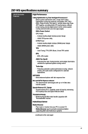
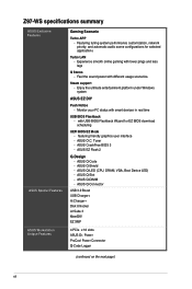
...ThunderboltEX II series HomeCloud Server Media Streamer - Industry leading digital 8-phase power design - ASUS CPU power utility DRAM Power - EPU, EPU switch ASUS Fan Xpert3 - UEFI BIOS - Design - Featuring Fan Auto Tuning function and multiple thermistors selection for portable smartphone/...and audio scene configuration for selected applications. Industry leading digital 2-phase DRAM power design - Z97-WS specifications summary ASUS Exclusive Features High Performance 5-Way Optimization by minimizing the coupling noise and signal reflection effect Thunderbolt Ready - Turbo App...
...ThunderboltEX II series HomeCloud Server Media Streamer - Industry leading digital 8-phase power design - ASUS CPU power utility DRAM Power - EPU, EPU switch ASUS Fan Xpert3 - UEFI BIOS - Design - Featuring Fan Auto Tuning function and multiple thermistors selection for portable smartphone/...and audio scene configuration for selected applications. Industry leading digital 2-phase DRAM power design - Z97-WS specifications summary ASUS Exclusive Features High Performance 5-Way Optimization by minimizing the coupling noise and signal reflection effect Thunderbolt Ready - Turbo App...
User Guide
Page 12
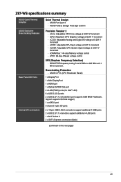
... smart devices in real time USB BIOS Flashback - Steam support - Enjoy the ultimate entertainment platform under Windows system ASUS EZ DIY Push Notice - ASUS O.C. ASUS Q-Code - ASUS Q-DIMM - featuring friendly graphics user interface - Monitor your PC status with different usage scenarios. ASUS EZ Flash 2 Q-Design - Z97-WS specifications summary ASUS Exclusive Features ASUS Special Features ASUS Workstation Unique Features Gaming Scenario...
... smart devices in real time USB BIOS Flashback - Steam support - Enjoy the ultimate entertainment platform under Windows system ASUS EZ DIY Push Notice - ASUS O.C. ASUS Q-Code - ASUS Q-DIMM - featuring friendly graphics user interface - Monitor your PC status with different usage scenarios. ASUS EZ Flash 2 Q-Design - Z97-WS specifications summary ASUS Exclusive Features ASUS Special Features ASUS Workstation Unique Features Gaming Scenario...
User Guide
Page 13
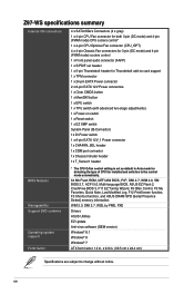
...BIOS Flashback, top port supports Q-Code Logger) 1 x eSATA port 8-channel Audio I /O connectors Quiet Thermal Design - vCCIN: Adjustable CPU Input voltage at 0.001 V increment - vCore: Adjustable CPU Core voltage at 0.01 V increment - vCCSA: Adjustable CPU System Agent voltage at 0.001 V increment - ASUS...I/O voltage at 0.001 V increment - ASUS Fanless Design: Heat-pipe solution Precision Tweaker 2 - iGPU: Adjustable CPU Graphics voltage at 0.1 MHz increment. Z97-WS specifications summary ASUS Quiet Thermal Solution ASUS Exclusive Overclocking Features Rear Panel I/O Ports ...
...BIOS Flashback, top port supports Q-Code Logger) 1 x eSATA port 8-channel Audio I /O connectors Quiet Thermal Design - vCCIN: Adjustable CPU Input voltage at 0.001 V increment - vCore: Adjustable CPU Core voltage at 0.01 V increment - vCCSA: Adjustable CPU System Agent voltage at 0.001 V increment - ASUS...I/O voltage at 0.001 V increment - ASUS Fanless Design: Heat-pipe solution Precision Tweaker 2 - iGPU: Adjustable CPU Graphics voltage at 0.1 MHz increment. Z97-WS specifications summary ASUS Quiet Thermal Solution ASUS Exclusive Overclocking Features Rear Panel I/O Ports ...
User Guide
Page 14
...1 x TPM connector 1 x 24-pin EATX Power connector 2 x 8-pin EATX 12V Power connectors 1 x Clear CMOS button 1 x MemOK! Z97-WS specifications summary Internal I/O connectors BIOS features Manageability Support DVD contents Operating system support Form factor 4 x SATA 6Gb/s Connectors (4 x gray) 1 x 4-pin CPU Fan connector for both...fan installed and switches to the control mode automatically. 64 Mb Flash ROM, UEFI AMI BIOS, PnP, DMI 2.7, WfM 2.0, SM BIOS 2.7, ACPI 5.0, Multi-language BIOS, ASUS EZ Flash 2, CrashFree BIOS 3, F11 EZ Tuning Wizard, F6 Qfan Control, F3 My Favorites, Quick Note, ...
...1 x TPM connector 1 x 24-pin EATX Power connector 2 x 8-pin EATX 12V Power connectors 1 x Clear CMOS button 1 x MemOK! Z97-WS specifications summary Internal I/O connectors BIOS features Manageability Support DVD contents Operating system support Form factor 4 x SATA 6Gb/s Connectors (4 x gray) 1 x 4-pin CPU Fan connector for both...fan installed and switches to the control mode automatically. 64 Mb Flash ROM, UEFI AMI BIOS, PnP, DMI 2.7, WfM 2.0, SM BIOS 2.7, ACPI 5.0, Multi-language BIOS, ASUS EZ Flash 2, CrashFree BIOS 3, F11 EZ Tuning Wizard, F6 Qfan Control, F3 My Favorites, Quick Note, ...
User Guide
Page 21
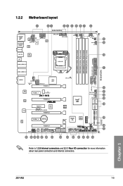
...CPU_OPT CPU_FAN 4 5 67 2 EPU OLED2 TPU I /O connection for more information about rear panel connectors and internal connectors. Chapter 1 Z97-WS 1-5 XLED1 EZ_XMP EATXPWR USB3_E56 mDP ASM 1042AE LAN2_USB3_34 LGA1150 LAN1_USB3_12 8 9 10 1 DDR3 DIMM_A1 (64bit, 240-pin module) DDR3 DIMM_A2 ...8747 DIAG_CPU LED USB3_34 WGI 210AT WGI 218LM TPU PCIEX1_1 ICS 9DB433AGLF Z97-WS PCIEX16_2 PCIEX4_1 ASM 1187e TB_HEADER PCIEX16_3 Intel® Z97 CHA_FAN3 DR.Power LED DR_POWER SATA6G_1 SATA6G_2 BIOS SATA6G_3 SATA6G_4 M.2(SOCKET3) ALC 1150 PCIEX1_2 Lithium Cell CMOS Power ...
...CPU_OPT CPU_FAN 4 5 67 2 EPU OLED2 TPU I /O connection for more information about rear panel connectors and internal connectors. Chapter 1 Z97-WS 1-5 XLED1 EZ_XMP EATXPWR USB3_E56 mDP ASM 1042AE LAN2_USB3_34 LGA1150 LAN1_USB3_12 8 9 10 1 DDR3 DIMM_A1 (64bit, 240-pin module) DDR3 DIMM_A2 ...8747 DIAG_CPU LED USB3_34 WGI 210AT WGI 218LM TPU PCIEX1_1 ICS 9DB433AGLF Z97-WS PCIEX16_2 PCIEX4_1 ASM 1187e TB_HEADER PCIEX16_3 Intel® Z97 CHA_FAN3 DR.Power LED DR_POWER SATA6G_1 SATA6G_2 BIOS SATA6G_3 SATA6G_4 M.2(SOCKET3) ALC 1150 PCIEX1_2 Lithium Cell CMOS Power ...
User Guide
Page 30
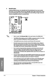
3. Z97-WS Z97-WS MemOK! The blinking speed of the DRAM_LED. • The DRAM_LED also lights up due to boot and load the BIOS default settings. A message will appear during the tuning process, the system continues memory tuning after turning on the computer. button lights continuously. ... with ones recommended in the Memory QVL (Qualified Vendors Lists) in this user manual or at www.asus.com. • If you download and update to the latest BIOS version from www.asus.com after the whole tuning process, the DRAM_LED lights continuously. It takes about 5-10 seconds. •...
3. Z97-WS Z97-WS MemOK! The blinking speed of the DRAM_LED. • The DRAM_LED also lights up due to boot and load the BIOS default settings. A message will appear during the tuning process, the system continues memory tuning after turning on the computer. button lights continuously. ... with ones recommended in the Memory QVL (Qualified Vendors Lists) in this user manual or at www.asus.com. • If you download and update to the latest BIOS version from www.asus.com after the whole tuning process, the DRAM_LED lights continuously. It takes about 5-10 seconds. •...
User Guide
Page 31
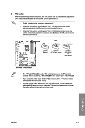
... is powered off. • When the TPU switch is set to section 1.2.8 Onboard LEDs for a more enhanced performance. TPU Z97-WS Disable (Default) Enabled (CPU Ratio Boost) Enabled (CPU BCLK and Ratio Boost) Z97-WS TPU switch • The TPU LED (TPU_LED) near the TPU switch lights up when the TPU switch is set... will be activated after the next system bootup. • You may use the 5-Way Optimization and TPU feature in the AI Suite 3 application, adjust the BIOS setup program or enable the TPU switch at the same time. Chapter 1 Z97-WS 1-15 4.
... is powered off. • When the TPU switch is set to section 1.2.8 Onboard LEDs for a more enhanced performance. TPU Z97-WS Disable (Default) Enabled (CPU Ratio Boost) Enabled (CPU BCLK and Ratio Boost) Z97-WS TPU switch • The TPU LED (TPU_LED) near the TPU switch lights up when the TPU switch is set... will be activated after the next system bootup. • You may use the 5-Way Optimization and TPU feature in the AI Suite 3 application, adjust the BIOS setup program or enable the TPU switch at the same time. Chapter 1 Z97-WS 1-15 4.
User Guide
Page 32
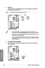
... EPU function at the same time. EPU switch Enable this button to clear the BIOS setup information only when the systems hangs due to automatically detect the current PC loadings and intelligently moderate the power consumption. Chapter 1 Z97-WS Z97-WS CLR_CMOS button 1-16 Chapter 1: Product introduction Clear CMOS button (CLR_CMOS) Press this switch to...
... EPU function at the same time. EPU switch Enable this button to clear the BIOS setup information only when the systems hangs due to automatically detect the current PC loadings and intelligently moderate the power consumption. Chapter 1 Z97-WS Z97-WS CLR_CMOS button 1-16 Chapter 1: Product introduction Clear CMOS button (CLR_CMOS) Press this switch to...
User Guide
Page 42
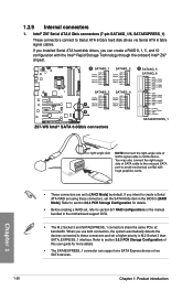
...Z97 Serial ATA 6 Gb/s connectors (7-pin SATA6G_1/6, SATAEXPRESS_1) These connectors connect to [RAID Mode]. If you installed Serial ATA hard disk drives, you use both connectors, the system automatically detects the devices connected to these connectors, set a higher priority to section 5.1 RAID configurations or the manual bundled in the BIOS... GND RSATA_TXP3 RSATA_TXN3 GND A RSATA_RXN3 RSATA_RXP3 GND GND RSATA_TXP4 RSATA_TXN4 GND RSATA_RXN4 RSATA_RXP4 GND B Z97-WS Intel® SATA 6.0Gb/s connectors B SATA6G_5 SATA6G_6 GND RSATA_TXP5 RSATA_TXN5 GND RSATA_RXN5 RSATA_RXP5 GND...
...Z97 Serial ATA 6 Gb/s connectors (7-pin SATA6G_1/6, SATAEXPRESS_1) These connectors connect to [RAID Mode]. If you installed Serial ATA hard disk drives, you use both connectors, the system automatically detects the devices connected to these connectors, set a higher priority to section 5.1 RAID configurations or the manual bundled in the BIOS... GND RSATA_TXP3 RSATA_TXN3 GND A RSATA_RXN3 RSATA_RXP3 GND GND RSATA_TXP4 RSATA_TXN4 GND RSATA_RXN4 RSATA_RXP4 GND B Z97-WS Intel® SATA 6.0Gb/s connectors B SATA6G_5 SATA6G_6 GND RSATA_TXP5 RSATA_TXN5 GND RSATA_RXN5 RSATA_RXP5 GND...
User Guide
Page 44
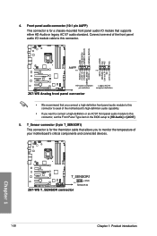
...-mounted front panel audio I /O module cable to this connector to [HD Audio] or [AC97]. 5. GND PRESENCE# SENSE1_RETUR SENSE2_RETUR AGND NC NC NC Z97-WS AAFP PIN 1 PIN 1 MIC2 MICPWR Line out_R NC Line out_L PORT1 L PORT1 R PORT2 R SENSE_SEND PORT2 L HD-audio-compliant Legacy AC'97 pin...definition or an AC'97 front panel audio module to this connector, set the Front Panel Type item in the BIOS setup to avail of your motherboard's critical components and connected devices. Chapter 1 Z97-WS T_SENSOR1 GND PIN 1 SENSOR IN Z97-WS T_SENSOR connector 1-28 Chapter 1: Product introduction
...-mounted front panel audio I /O module cable to this connector to [HD Audio] or [AC97]. 5. GND PRESENCE# SENSE1_RETUR SENSE2_RETUR AGND NC NC NC Z97-WS AAFP PIN 1 PIN 1 MIC2 MICPWR Line out_R NC Line out_L PORT1 L PORT1 R PORT2 R SENSE_SEND PORT2 L HD-audio-compliant Legacy AC'97 pin...definition or an AC'97 front panel audio module to this connector, set the Front Panel Type item in the BIOS setup to avail of your motherboard's critical components and connected devices. Chapter 1 Z97-WS T_SENSOR1 GND PIN 1 SENSOR IN Z97-WS T_SENSOR connector 1-28 Chapter 1: Product introduction
User Guide
Page 48
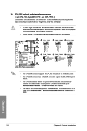
...Monitor > CPU Q-Fan Control item in BIOS. Chapter 1 1-32 Chapter 1: Product introduction A A CPU_OPT B CHA_FAN4 C CPU_FAN B C CPU FAN PWM CPU FAN IN CPU FAN PWR GND +5V CHA FAN IN CHA FAN PWR GND CPU FAN PWM CPU FAN IN CPU FAN PWR GND D E Z97-WS F Z97-WS Fan connectors D CHA_FAN1 E CHA_FAN3 F ...8226; The CPU_FAN connector supports the CPU fan of maximum 1A (12 W) fan power. • The CPU_FAN connector and CHA_FAN connectors support the ASUS FAN Xpert 3 feature. • The CPU fan connector detects the type of the connector. • DO NOT forget to connect the fan cables...
...Monitor > CPU Q-Fan Control item in BIOS. Chapter 1 1-32 Chapter 1: Product introduction A A CPU_OPT B CHA_FAN4 C CPU_FAN B C CPU FAN PWM CPU FAN IN CPU FAN PWR GND +5V CHA FAN IN CHA FAN PWR GND CPU FAN PWM CPU FAN IN CPU FAN PWR GND D E Z97-WS F Z97-WS Fan connectors D CHA_FAN1 E CHA_FAN3 F ...8226; The CPU_FAN connector supports the CPU fan of maximum 1A (12 W) fan power. • The CPU_FAN connector and CHA_FAN connectors support the ASUS FAN Xpert 3 feature. • The CPU fan connector detects the type of the connector. • DO NOT forget to connect the fan cables...
User Guide
Page 65
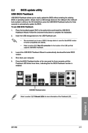
... and install the USB BIOS Flashback Wizard. Insert the USB storage device to the USB Flashback port. • We recommend you to easily update the BIOS without entering the existing BIOS or operating system. Chapter 2 Z97-WS 2-11 Press the BIOS Flashback button at the ...rear panel for more information of the USB port that the BIOS Flashback function is enabled. 2.2 BIOS update utility USB BIOS Flashback USB BIOS Flashback allows you ...
... and install the USB BIOS Flashback Wizard. Insert the USB storage device to the USB Flashback port. • We recommend you to easily update the BIOS without entering the existing BIOS or operating system. Chapter 2 Z97-WS 2-11 Press the BIOS Flashback button at the ...rear panel for more information of the USB port that the BIOS Flashback function is enabled. 2.2 BIOS update utility USB BIOS Flashback USB BIOS Flashback allows you ...

User Guide
Page 66
Simply insert a USB storage device to the USB port (the USB port hole marked in green on the I/O shield) then press the USB BIOS Flashback button for five seconds and turns into a solid light, this scenario happens, please restart the system to automatically store the Q-Code event logs... is damaged during the process and results to the system's failure to the section 3.11 Updating BIOS in BIOS setup, refer to boot up, please contact your local ASUS Service Center. Q-Code Logger Q-Code Logger allows you to the Q-Code Logger port. 2. Insert the USB storage device to easily check Q-...
Simply insert a USB storage device to the USB port (the USB port hole marked in green on the I/O shield) then press the USB BIOS Flashback button for five seconds and turns into a solid light, this scenario happens, please restart the system to automatically store the Q-Code event logs... is damaged during the process and results to the system's failure to the section 3.11 Updating BIOS in BIOS setup, refer to boot up, please contact your local ASUS Service Center. Q-Code Logger Q-Code Logger allows you to the Q-Code Logger port. 2. Insert the USB storage device to easily check Q-...

User Guide
Page 67
Mini DisplayPort 6. USB 3.0 ports 3 and 4 13. HDMI port 3. DisplayPort 9. USB 3.0 ports 1 and 2 14. Q-Code Logger button 5. eSATA port 10. Chapter 2 Z97-WS 2-13 Intel® LAN port (LAN1)* 8. USB 3.0 ports 5 and 6 12. 2.3 Motherboard rear and audio connections 2.3.1 Rear I /O ports** * and **: Refer to the ... for LAN port LEDs and audio port definitions. USB 2.0 ports 5 and 6 4. Optical S/PDIF Out port 2. Intel® LAN port (LAN2)* 7. USB BIOS Flashback button 11. Audio I /O connection 123 4 5 6 7 8 9 10 11 12 13 14 Rear panel connectors 1.
Mini DisplayPort 6. USB 3.0 ports 3 and 4 13. HDMI port 3. DisplayPort 9. USB 3.0 ports 1 and 2 14. Q-Code Logger button 5. eSATA port 10. Chapter 2 Z97-WS 2-13 Intel® LAN port (LAN1)* 8. USB 3.0 ports 5 and 6 12. 2.3 Motherboard rear and audio connections 2.3.1 Rear I /O ports** * and **: Refer to the ... for LAN port LEDs and audio port definitions. USB 2.0 ports 5 and 6 4. Optical S/PDIF Out port 2. Intel® LAN port (LAN2)* 7. USB BIOS Flashback button 11. Audio I /O connection 123 4 5 6 7 8 9 10 11 12 13 14 Rear panel connectors 1.
User Guide
Page 68
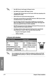
... connection Orange 100 Mbps connection Green 1 Gbps connection Orange (Blinking Ready to wake up to three displays under Windows® OS environment, two displays under BIOS, and one display under DOS. • Intel display architecture design supports the following maximum supported pixel clocks (Pixel Clock = H total x V Total x Frame Rate (Fresh screen... USB 3.0 device may run on xHCI mode or EHCI mode, depending on the operating system's setting. • USB 3.0 devices can disable the LAN controllers in BIOS.
... connection Orange 100 Mbps connection Green 1 Gbps connection Orange (Blinking Ready to wake up to three displays under Windows® OS environment, two displays under BIOS, and one display under DOS. • Intel display architecture design supports the following maximum supported pixel clocks (Pixel Clock = H total x V Total x Frame Rate (Fresh screen... USB 3.0 device may run on xHCI mode or EHCI mode, depending on the operating system's setting. • USB 3.0 devices can disable the LAN controllers in BIOS.
User Guide
Page 71
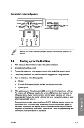
...system power LED on self tests (POST). Connect the power cord to green after the system LED turns on the devices in the following order: a. Z97-WS 2-17 Chapter 2 Ensure that is enabled, ensure to connect the rear speaker to the gray port. 2.4 Starting up . System power 6. If ...to 7.1 channel Speakers When the DTS UltraPC II function is equipped with a surge protector. 5. After making all switches are running, the BIOS beeps (refer to the BIOS beep codes table) or additional messages appear on the chain) c. Turn on . For systems with ATX power supplies, the system LED ...
...system power LED on self tests (POST). Connect the power cord to green after the system LED turns on the devices in the following order: a. Z97-WS 2-17 Chapter 2 Ensure that is enabled, ensure to connect the rear speaker to the gray port. 2.4 Starting up . System power 6. If ...to 7.1 channel Speakers When the DTS UltraPC II function is equipped with a surge protector. 5. After making all switches are running, the BIOS beeps (refer to the BIOS beep codes table) or additional messages appear on the chain) c. Turn on . For systems with ATX power supplies, the system LED ...

