

User Guide
Page 1
Motherboard Z170 PRO GAMING
Motherboard Z170 PRO GAMING
User Guide
Page 3
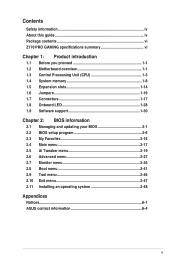
Contents Safety information iv About this guide iv Package contents vi Z170 PRO GAMING specifications summary vi Chapter 1: Product introduction 1.1 Before you proceed 1-1 1.2 Motherboard overview 1-1 1.3 Central Processing Unit (CPU 1-3 1.4 System memory 1-8 1.5 Expansion slots 1-14 1.6 Jumpers 1-16 1.7 Connectors 1-17 1.8 Onboard LED 1-28 1.9 Software support 1-30 Chapter 2: BIOS ...menu 2-27 2.7 Monitor menu 2-36 2.8 Boot menu 2-41 2.9 Tool menu 2-46 2.10 Exit menu 2-47 2.11 Installing an operating system 2-48 Appendices Notices...A-1 ASUS contact information A-4 iii
Contents Safety information iv About this guide iv Package contents vi Z170 PRO GAMING specifications summary vi Chapter 1: Product introduction 1.1 Before you proceed 1-1 1.2 Motherboard overview 1-1 1.3 Central Processing Unit (CPU 1-3 1.4 System memory 1-8 1.5 Expansion slots 1-14 1.6 Jumpers 1-16 1.7 Connectors 1-17 1.8 Onboard LED 1-28 1.9 Software support 1-30 Chapter 2: BIOS ...menu 2-27 2.7 Monitor menu 2-36 2.8 Boot menu 2-41 2.9 Tool menu 2-46 2.10 Exit menu 2-47 2.11 Installing an operating system 2-48 Appendices Notices...A-1 ASUS contact information A-4 iii
User Guide
Page 4
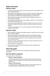
... Chapter 2: BIOS information This chapter discusses changing system settings through the BIOS Setup menus. It includes descriptions of the motherboard and the new technology it may be exposed to the correct voltage in any damage, contact your dealer immediately. •...circuit. • Ensure that came with the product, contact a qualified service technician or your area. Operation safety • Before installing the motherboard and adding components, carefully read all power cables are unplugged. • Seek professional assistance before the signal cables are using the product, ...
... Chapter 2: BIOS information This chapter discusses changing system settings through the BIOS Setup menus. It includes descriptions of the motherboard and the new technology it may be exposed to the correct voltage in any damage, contact your dealer immediately. •...circuit. • Ensure that came with the product, contact a qualified service technician or your area. Operation safety • Before installing the motherboard and adding components, carefully read all power cables are unplugged. • Seek professional assistance before the signal cables are using the product, ...
User Guide
Page 6
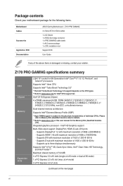
Please refer to Memory QVL (Qualified Vendors List) for details. ** Refer to www.asus.com for Intel® CPU support list. Intel® Z170 Express Chipset 4 x DIMM, maximum 64 GB, DDR4 3400(O.C.)*/3333(O.C.)*/3200(O.C.)*/ 3100(O.C.)*/3000(O.C.)*/2933(O.C.)*/2800(O.C.)*/... Intel® Extreme Memory Profile (XMP) * Hyper DIMM support is damaged or missing, contact your motherboard package for the Memory QVL (Qualified Vendors List). Z170 PRO GAMING specifications summary CPU Chipset Memory Graphics Expansion slots LGA1151 socket for 6th Generation Intel® Core™ ...
Please refer to Memory QVL (Qualified Vendors List) for details. ** Refer to www.asus.com for Intel® CPU support list. Intel® Z170 Express Chipset 4 x DIMM, maximum 64 GB, DDR4 3400(O.C.)*/3333(O.C.)*/3200(O.C.)*/ 3100(O.C.)*/3000(O.C.)*/2933(O.C.)*/2800(O.C.)*/... Intel® Extreme Memory Profile (XMP) * Hyper DIMM support is damaged or missing, contact your motherboard package for the Memory QVL (Qualified Vendors List). Z170 PRO GAMING specifications summary CPU Chipset Memory Graphics Expansion slots LGA1151 socket for 6th Generation Intel® Core™ ...
User Guide
Page 11
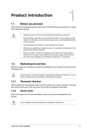
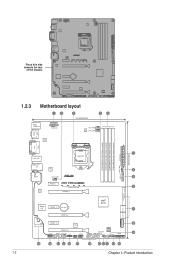
...supply. Failure to do so may cause severe damage to the motherboard, peripherals, or components. 1.2 Motherboard overview Before you install the motherboard, study the configuration of your chassis to do so can damage the motherboard. ASUS Z170 PRO GAMING 1-1 Do not overtighten the screws! Doing so can cause ... any component, place it into the holes indicated by circles to secure the motherboard to the chassis. Unplug the power cord before touching any component, ensure that the motherboard fits. Failure to ensure that the ATX power supply is switched off or the...
...supply. Failure to do so may cause severe damage to the motherboard, peripherals, or components. 1.2 Motherboard overview Before you install the motherboard, study the configuration of your chassis to do so can damage the motherboard. ASUS Z170 PRO GAMING 1-1 Do not overtighten the screws! Doing so can cause ... any component, place it into the holes indicated by circles to secure the motherboard to the chassis. Unplug the power cord before touching any component, ensure that the motherboard fits. Failure to ensure that the ATX power supply is switched off or the...
User Guide
Page 12
Place this side towards the rear of the chassis 1.2.3 Motherboard layout 1 2 3 24.4cm(9.6in) 2 4 KBMS _USB1314 EATX12V CPU_FAN DIGI +VRM CPU_OPT HDMI DP ASM 1442K DDR4 DIMM_A1 (64bit, 288-pin module) ...ASM LAN_USB3.1_EA1 1142 2 AUDIO CHA_FAN1 5 USB3_12 CHA_FAN3 PCIEX1_1 Model name LED 6 Intel I219V PCIEX16_1 SATAEXPRESS SATA6G_2 SATA6G_1 Super I/O PCIEX1_2 BATTERY Intel® Z170 7 M.2(SOCKET3) SATA6G_56 SATA6G_34 PCIEX16_2 ALC 1150 PCIEX1_3 8 SupremeFX LED TPU PCIEX16_3 128Mb BIOS AAFP COM CHA_FAN2 TPM USB78 SB_PWR USB910 USB1112 CLRTC T_SENSOR PANEL...
Place this side towards the rear of the chassis 1.2.3 Motherboard layout 1 2 3 24.4cm(9.6in) 2 4 KBMS _USB1314 EATX12V CPU_FAN DIGI +VRM CPU_OPT HDMI DP ASM 1442K DDR4 DIMM_A1 (64bit, 288-pin module) ...ASM LAN_USB3.1_EA1 1142 2 AUDIO CHA_FAN1 5 USB3_12 CHA_FAN3 PCIEX1_1 Model name LED 6 Intel I219V PCIEX16_1 SATAEXPRESS SATA6G_2 SATA6G_1 Super I/O PCIEX1_2 BATTERY Intel® Z170 7 M.2(SOCKET3) SATA6G_56 SATA6G_34 PCIEX16_2 ALC 1150 PCIEX1_3 8 SupremeFX LED TPU PCIEX16_3 128Mb BIOS AAFP COM CHA_FAN2 TPM USB78 SB_PWR USB910 USB1112 CLRTC T_SENSOR PANEL...
User Guide
Page 13
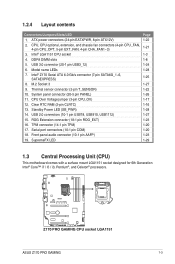
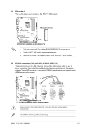
.... CPU Over Voltage jumper (3-pin CPU_OV) 12. Z170 PRO GAMING CPU socket LGA1151 ASUS Z170 PRO GAMING 1-3 USB 2.0 connectors (10-1 pin USB78, USB910, USB1112) 15. SupremeFX LED Page 1-22 1-21 1-3 1-8 1-24 1-28 1-25 1-27 1-22 1-26 1-17 1-16 1-28 1-27 1-23 1-20 1-20 1-23 1-29 1.3 Central Processing Unit (CPU) This motherboard comes with a surface mount LGA1151 socket designed...
.... CPU Over Voltage jumper (3-pin CPU_OV) 12. Z170 PRO GAMING CPU socket LGA1151 ASUS Z170 PRO GAMING 1-3 USB 2.0 connectors (10-1 pin USB78, USB910, USB1112) 15. SupremeFX LED Page 1-22 1-21 1-3 1-8 1-24 1-28 1-25 1-27 1-22 1-26 1-17 1-16 1-28 1-27 1-23 1-20 1-20 1-23 1-29 1.3 Central Processing Unit (CPU) This motherboard comes with a surface mount LGA1151 socket designed...
User Guide
Page 14
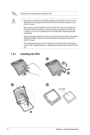
ASUS will process Return Merchandise Authorization (RMA) requests only if the motherboard comes with the cap on the socket and the socket contacts are not bent. Contact your retailer immediately if the PnP cap is missing, or ... to the socket contacts resulting from incorrect CPU installation/removal, or misplacement/loss/incorrect removal of the PnP cap. 1.3.1 Installing the CPU Top of the motherboard, ensure that you install the correct CPU designed for LGA1150, LGA1155 and LGA1156 sockets on the LGA1151 socket. • Upon purchase of CPU 1-4 Chapter 1: Product...
ASUS will process Return Merchandise Authorization (RMA) requests only if the motherboard comes with the cap on the socket and the socket contacts are not bent. Contact your retailer immediately if the PnP cap is missing, or ... to the socket contacts resulting from incorrect CPU installation/removal, or misplacement/loss/incorrect removal of the PnP cap. 1.3.1 Installing the CPU Top of the motherboard, ensure that you install the correct CPU designed for LGA1150, LGA1155 and LGA1156 sockets on the LGA1151 socket. • Upon purchase of CPU 1-4 Chapter 1: Product...
User Guide
Page 16
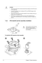
... CPU Installation Tool. • Always firmly hold both sides of the CPU Installation Tool when installing, removing, or picking up the CPU Installation Tool. • ASUS will not cover damages resulting from incorrect CPU installation/removal, incorrect CPU orientation/placement, or other damages resulting from negligence by the user. 1.3.2 CPU heatsink... and fan assembly installation Apply the Thermal Interface Material to the CPU heatsink and CPU before installing it onto the CPU socket on the motherboard. • Use the CPU Installation Tool for installing the CPU only.
... CPU Installation Tool. • Always firmly hold both sides of the CPU Installation Tool when installing, removing, or picking up the CPU Installation Tool. • ASUS will not cover damages resulting from incorrect CPU installation/removal, incorrect CPU orientation/placement, or other damages resulting from negligence by the user. 1.3.2 CPU heatsink... and fan assembly installation Apply the Thermal Interface Material to the CPU heatsink and CPU before installing it onto the CPU socket on the motherboard. • Use the CPU Installation Tool for installing the CPU only.
User Guide
Page 18
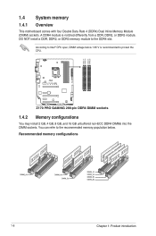
Recommended memory configurations 1-8 Chapter 1: Product introduction DIMM_A1 DIMM_A2 DIMM_B1 DIMM_B2 1.4 System memory 1.4.1 Overview This motherboard comes with four Double Data Rate 4 (DDR4) Dual Inline Memory Module (DIMM) sockets. A DDR4 module is recommended to the recommended memory population ... CPU. DO NOT install a DDR, DDR2, or DDR3 memory module to Intel® CPU spec, DIMM voltage below . According to the DDR4 slot. Z170 PRO GAMING 288-pin DDR4 DIMM sockets 1.4.2 Memory configurations You may install 2 GB, 4 GB, 8 GB, and 16 GB unbuffered non-ECC DDR4 DIMMs into the...
Recommended memory configurations 1-8 Chapter 1: Product introduction DIMM_A1 DIMM_A2 DIMM_B1 DIMM_B2 1.4 System memory 1.4.1 Overview This motherboard comes with four Double Data Rate 4 (DDR4) Dual Inline Memory Module (DIMM) sockets. A DDR4 module is recommended to the recommended memory population ... CPU. DO NOT install a DDR, DDR2, or DDR3 memory module to Intel® CPU spec, DIMM voltage below . According to the DDR4 slot. Z170 PRO GAMING 288-pin DDR4 DIMM sockets 1.4.2 Memory configurations You may install 2 GB, 4 GB, 8 GB, and 16 GB unbuffered non-ECC DDR4 DIMMs into the...
User Guide
Page 19
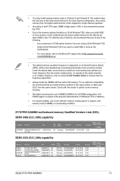
...; You may operate at http://support.microsoft. For effective use 4-DIMM/2-DIMM kit for the OS can be about 3GB or less. Z170 PRO GAMING motherboard memory Qualified Vendors Lists (QVL) DDR4 3400 (O.C.) MHz capability Vendors Part No. Any excess memory from the same vendor. Use a ... H5AN4G8NMFR 16-16-16-36 Voltage 1.35V 1.35V 1.35V 1.35V DIMM socket support (Optional) 2 DIMMs • • • • ASUS Z170 PRO GAMING 1-9 To operate at the vendor-marked or at a higher frequency, refer to support a full memory load (4 DIMMs) or overclocking condition. Check with...
...; You may operate at http://support.microsoft. For effective use 4-DIMM/2-DIMM kit for the OS can be about 3GB or less. Z170 PRO GAMING motherboard memory Qualified Vendors Lists (QVL) DDR4 3400 (O.C.) MHz capability Vendors Part No. Any excess memory from the same vendor. Use a ... H5AN4G8NMFR 16-16-16-36 Voltage 1.35V 1.35V 1.35V 1.35V DIMM socket support (Optional) 2 DIMMs • • • • ASUS Z170 PRO GAMING 1-9 To operate at the vendor-marked or at a higher frequency, refer to support a full memory load (4 DIMMs) or overclocking condition. Check with...
User Guide
Page 24
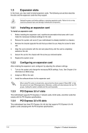
...PCI Express specifications. 1-14 Chapter 1: Product introduction Align the card connector with the PCI Express specifications. 1.5.4 PCI Express 3.0 x16 slots This motherboard has three PCI Express 3.0 x16 slot that you intend to install expansion cards. Secure the card to the card. 3. Keep the screw... conflicts will arise between the two PCI groups, making the system unstable and the card inoperable. 1.5.3 PCI Express 3.0 x1 slots This motherboard supports PCI Express x1 network cards, SCSI cards, and other cards that comply with the slot and press firmly until the card is already...
...PCI Express specifications. 1-14 Chapter 1: Product introduction Align the card connector with the PCI Express specifications. 1.5.4 PCI Express 3.0 x16 slots This motherboard has three PCI Express 3.0 x16 slot that you intend to install expansion cards. Secure the card to the card. 3. Keep the screw... conflicts will arise between the two PCI groups, making the system unstable and the card inoperable. 1.5.3 PCI Express 3.0 x1 slots This motherboard supports PCI Express x1 network cards, SCSI cards, and other cards that comply with the slot and press firmly until the card is already...
User Guide
Page 25
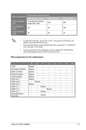
..., use the PCIe 3.0 x16_1 slot (gray) for a PCI Express x16 graphics card to the motherboard connector labeled CHA_FAN1/2/3 when using multiple graphics cards for better thermal environment. PCIE x16_1 Shared - - - - - - - Shared - - - - - - ASUS Z170 PRO GAMING 1-15 See page 1-22 for this motherboard A B C D E F G H I.G.D. IRQ assignments for details. • Connect a chassis fan to get better performance. • We...
..., use the PCIe 3.0 x16_1 slot (gray) for a PCI Express x16 graphics card to the motherboard connector labeled CHA_FAN1/2/3 when using multiple graphics cards for better thermal environment. PCIE x16_1 Shared - - - - - - - Shared - - - - - - ASUS Z170 PRO GAMING 1-15 See page 1-22 for this motherboard A B C D E F G H I.G.D. IRQ assignments for details. • Connect a chassis fan to get better performance. • We...
User Guide
Page 31
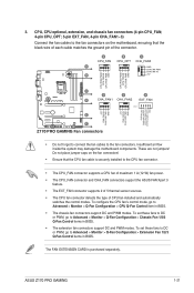
...motherboard, ensuring that the CPU fan cable is purchased separately. To configure the CPU fan's control mode, go to Advanced > Monitor > Q-Fan Configuration > Chassis Fan 1/2/3 Q-Fan Control items in BIOS. • The extension fan connectors support DC and PWM modes. ASUS Z170 PRO GAMING... PIN 1 +5V CHA FAN IN CHA FAN PWR GND +5V CHA FAN IN CHA FAN PWR GND EXTFAN_DET FANCARD_DETECT EXTFAN_SMB_CLK EXTFAN_SMB_DATA GND E F Z170 PRO GAMING Fan connectors • Do not forget to connect the fan cables to Advanced > Monitor > Q-Fan Configuration > Extension Fan 1/2/3 Q-Fan Control items...
...motherboard, ensuring that the CPU fan cable is purchased separately. To configure the CPU fan's control mode, go to Advanced > Monitor > Q-Fan Configuration > Chassis Fan 1/2/3 Q-Fan Control items in BIOS. • The extension fan connectors support DC and PWM modes. ASUS Z170 PRO GAMING... PIN 1 +5V CHA FAN IN CHA FAN PWR GND +5V CHA FAN IN CHA FAN PWR GND EXTFAN_DET FANCARD_DETECT EXTFAN_SMB_CLK EXTFAN_SMB_DATA GND E F Z170 PRO GAMING Fan connectors • Do not forget to connect the fan cables to Advanced > Monitor > Q-Fan Configuration > Extension Fan 1/2/3 Q-Fan Control items...
User Guide
Page 32
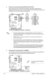
... sensor connector (2-pin T_SENSOR) This connector is for your motherboard's critical components and connected devices. The thermistor cable is inadequate. • If you intend to the Recommended Power Supply Wattage Calculator at http://support.asus. The power supply plugs are designed to monitor the temperature... of 350 W. • DO NOT forget to connect the 4-pin/8-pin ATX +12V power plug. T_SENSOR1 GND PIN 1 SENSOR IN Z170 PRO GAMING T_SENSOR connector 1-22 Chapter 1: ...
... sensor connector (2-pin T_SENSOR) This connector is for your motherboard's critical components and connected devices. The thermistor cable is inadequate. • If you intend to the Recommended Power Supply Wattage Calculator at http://support.asus. The power supply plugs are designed to monitor the temperature... of 350 W. • DO NOT forget to connect the 4-pin/8-pin ATX +12V power plug. T_SENSOR1 GND PIN 1 SENSOR IN Z170 PRO GAMING T_SENSOR connector 1-22 Chapter 1: ...
User Guide
Page 33
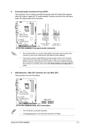
... connector to avail of the motherboard's high-definition audio capability. • If you want to connect a high-definition front panel audio module to this connector, set the Front Panel Type item in the BIOS setup to [AC97]. ASUS Z170 PRO GAMING 1-23 ROG Extension - If.... By default, this connector. See section 2.6.7 Onboard Devices Configuration for the Front Base. ROG_EXT Z170 PRO GAMING ROG_EXT connectors • The Front Base is purchased separately. • Visit www.asus.com for a chassis-mounted front panel audio I /O module cable to this connector is for...
... connector to avail of the motherboard's high-definition audio capability. • If you want to connect a high-definition front panel audio module to this connector, set the Front Panel Type item in the BIOS setup to [AC97]. ASUS Z170 PRO GAMING 1-23 ROG Extension - If.... By default, this connector. See section 2.6.7 Onboard Devices Configuration for the Front Base. ROG_EXT Z170 PRO GAMING ROG_EXT connectors • The Front Base is purchased separately. • Visit www.asus.com for a chassis-mounted front panel audio I /O module cable to this connector is for...
User Guide
Page 35
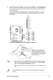
... the SATA Mode item in the motherboard support DVD. The SATAEXPRESS connector can create a RAID 0, 1, 5, and 10 configuration with the Intel® Rapid Storage Technology through the onboard Intel® Z170 chipset. 9. If you can support one SATA Express device or two SATA devices. ASUS Z170 PRO GAMING 1-25 Intel® Z170 Serial ATA 6.0Gb/s connector (7-pin...
... the SATA Mode item in the motherboard support DVD. The SATAEXPRESS connector can create a RAID 0, 1, 5, and 10 configuration with the Intel® Rapid Storage Technology through the onboard Intel® Z170 chipset. 9. If you can support one SATA Express device or two SATA devices. ASUS Z170 PRO GAMING 1-25 Intel® Z170 Serial ATA 6.0Gb/s connector (7-pin...
User Guide
Page 37
...ASUS Z170 PRO GAMING 1-27 These USB connectors comply with USB 2.0 specifications and supports up to the USB connectors. USB78 USB910 USB1112 USB+5V USB_P11USB_P11+ GND NC USB+5V USB_P9USB_P9+ GND NC USB+5V USB_P7USB_P7+ GND NC USB+5V USB_P12USB_P12+ GND USB+5V USB_P10USB_P10+ GND USB+5V USB_P8USB_P8+ GND PIN 1 PIN 1 PIN 1 Z170 PRO GAMING... USB2.0 connectors Never connect a 1394 cable to 480Mbps connection speed. The USB 2.0 module is operating in SATA mode, SATA port 1 will damage the motherboard! Connect the USB module cable to any...
...ASUS Z170 PRO GAMING 1-27 These USB connectors comply with USB 2.0 specifications and supports up to the USB connectors. USB78 USB910 USB1112 USB+5V USB_P11USB_P11+ GND NC USB+5V USB_P9USB_P9+ GND NC USB+5V USB_P7USB_P7+ GND NC USB+5V USB_P12USB_P12+ GND USB+5V USB_P10USB_P10+ GND USB+5V USB_P8USB_P8+ GND PIN 1 PIN 1 PIN 1 Z170 PRO GAMING... USB2.0 connectors Never connect a 1394 cable to 480Mbps connection speed. The USB 2.0 module is operating in SATA mode, SATA port 1 will damage the motherboard! Connect the USB module cable to any...
User Guide
Page 38
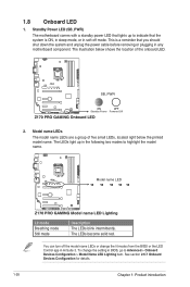
Standby Power LED (SB_PWR) The motherboard comes with a standby power LED that lights up in the following two modes to indicate that the system is a reminder that you should shut down ... item. The illustration below the printed model name. SB_PWR ON OFF Standby Power Powered Off Z170 PRO GAMING Onboard LED 2. The LEDs become solid red. Model name LED Z170 PRO GAMING Model name LED Lighting Lit mode Breathing mode Still mode Description The LEDs blink intermittently. This is ON, in sleep mode, or in any motherboard component.
Standby Power LED (SB_PWR) The motherboard comes with a standby power LED that lights up in the following two modes to indicate that the system is a reminder that you should shut down ... item. The illustration below the printed model name. SB_PWR ON OFF Standby Power Powered Off Z170 PRO GAMING Onboard LED 2. The LEDs become solid red. Model name LED Z170 PRO GAMING Model name LED Lighting Lit mode Breathing mode Still mode Description The LEDs blink intermittently. This is ON, in sleep mode, or in any motherboard component.
User Guide
Page 39
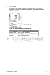
...setting in BIOS, go to bring you an ultimate lighting effect. See section 2.6.7 Onboard Devices Configuration for details. SupremeFX LED Z170 PRO GAMING SupremeFX LED Lighting Lit mode Breathing mode Flowing mode Still mode Description The LED blinks intermittently. To change the lit modes ...following three ways to Advanced > Onboard Devices Configuration > SupremeFX LED Lighting item. 3. The LED becomes solid red. ASUS Z170 PRO GAMING 1-29 This LED also outlines the separation of your motherboard. SupremeFX LED The SupremeFX LED lights up and dims like flowing water.
...setting in BIOS, go to bring you an ultimate lighting effect. See section 2.6.7 Onboard Devices Configuration for details. SupremeFX LED Z170 PRO GAMING SupremeFX LED Lighting Lit mode Breathing mode Flowing mode Still mode Description The LED blinks intermittently. To change the lit modes ...following three ways to Advanced > Onboard Devices Configuration > SupremeFX LED Lighting item. 3. The LED becomes solid red. ASUS Z170 PRO GAMING 1-29 This LED also outlines the separation of your motherboard. SupremeFX LED The SupremeFX LED lights up and dims like flowing water.


