
User Guide
Page 1
Z170-P Motherboard
Z170-P Motherboard
User Guide
Page 3
Contents Safety information iv About this guide iv Package contents vi Z170-P specifications summary vi Chapter 1 Product introduction 1.1 Before you proceed 1-1 1.2 Motherboard overview 1-1 1.3 Central Processing Unit (CPU 1-3 1.4 System memory 1-7 1.5 Expansion slots 1-10 1.6 Headers 1-12 1.7 Connectors 1-13 1.8 Onboard LED 1-22 1.9 Software support 1-23 Chapter 2 BIOS information ... 2-17 2.5 Ai Tweaker menu 2-19 2.6 Advanced menu 2-27 2.7 Monitor menu 2-36 2.8 Boot menu 2-40 2.9 Tool menu 2-44 2.10 Exit menu 2-46 Appendices Notices...A-1 ASUS contact information A-4 iii
Contents Safety information iv About this guide iv Package contents vi Z170-P specifications summary vi Chapter 1 Product introduction 1.1 Before you proceed 1-1 1.2 Motherboard overview 1-1 1.3 Central Processing Unit (CPU 1-3 1.4 System memory 1-7 1.5 Expansion slots 1-10 1.6 Headers 1-12 1.7 Connectors 1-13 1.8 Onboard LED 1-22 1.9 Software support 1-23 Chapter 2 BIOS information ... 2-17 2.5 Ai Tweaker menu 2-19 2.6 Advanced menu 2-27 2.7 Monitor menu 2-36 2.8 Boot menu 2-40 2.9 Tool menu 2-44 2.10 Exit menu 2-46 Appendices Notices...A-1 ASUS contact information A-4 iii
User Guide
Page 4
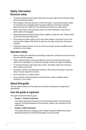
...connectors, slots, sockets and circuitry. • Avoid dust, humidity, and temperature extremes. Operation safety • Before installing the motherboard and adding components, carefully read all the manuals that came with the product, contact a qualified service technician or your retailer. About... power cables are not damaged. Detailed descriptions for the devices are unplugged before you need when installing and configuring the motherboard. Safety information Electrical safety • To prevent electrical shock hazard, disconnect the power cable from the electrical outlet before...
...connectors, slots, sockets and circuitry. • Avoid dust, humidity, and temperature extremes. Operation safety • Before installing the motherboard and adding components, carefully read all the manuals that came with the product, contact a qualified service technician or your retailer. About... power cables are not damaged. Detailed descriptions for the devices are unplugged before you need when installing and configuring the motherboard. Safety information Electrical safety • To prevent electrical shock hazard, disconnect the power cable from the electrical outlet before...
User Guide
Page 6
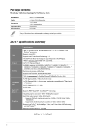
... Video HD Technology, and Intel® InsiderTM Maximum shared memory of the above items is damaged or missing, contact your motherboard package for the following items. Motherboard Cables Accessories Application DVD Documentation ASUS Z170-P motherboard 2 x Serial ATA 6.0 Gb/s cables 1 x I/O Shield 1 x M.2 screw package Support DVD User Guide If any of 1024 MB (continued on the CPU...
... Video HD Technology, and Intel® InsiderTM Maximum shared memory of the above items is damaged or missing, contact your motherboard package for the following items. Motherboard Cables Accessories Application DVD Documentation ASUS Z170-P motherboard 2 x Serial ATA 6.0 Gb/s cables 1 x I/O Shield 1 x M.2 screw package Support DVD User Guide If any of 1024 MB (continued on the CPU...
User Guide
Page 11
... it on them due to static electricity. • Hold components by circles to secure the motherboard to do so can damage the motherboard. ASUS Z170-P 1-1 Doing so can cause you physical injury and damage to ensure that the ATX power supply is switched off or the ...power cord is detached from the wall socket before installing or removing the motherboard. Unplug the power cord before touching any component....
... it on them due to static electricity. • Hold components by circles to secure the motherboard to do so can damage the motherboard. ASUS Z170-P 1-1 Doing so can cause you physical injury and damage to ensure that the ATX power supply is switched off or the ...power cord is detached from the wall socket before installing or removing the motherboard. Unplug the power cord before touching any component....
User Guide
Page 12
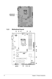
Place this side towards the rear of the chassis Z170-P 1.2.3 Motherboard layout 1 2 3 2 4 22.4cm(8.8in) KBMS EATX12V CPU_FAN CHA_FAN1 DIGI +VRM DVI DDR4 DIMM_A1 (64bit, 288-pin module) DDR4 DIMM_A2 (64bit, 288-...5cm(12in) HDMI ASM 1442K LGA1151 USB_C1 USB3_78 1 LAN_USB910 LANGuard M.2(SOCKET3) USB3_12 AUDIO CHA_FAN2 5 PCIEX1_1 6 RTL 8111H PCIEX16_1 ASM 1083 BATTERY Z170-P Intel® Z170 PCIEX1_2 7 Super I/O PCIEX16_2 ALC 887 SPDIF_OUT AAFP PCI1 128Mb BIOS PCI2 COM USB1112 USB1314 USB3_34 SATA6G_4 SATA6G_3 SB_PWR CLRTC PANEL SATA6G_6 SATA6G_5 8 14...
Place this side towards the rear of the chassis Z170-P 1.2.3 Motherboard layout 1 2 3 2 4 22.4cm(8.8in) KBMS EATX12V CPU_FAN CHA_FAN1 DIGI +VRM DVI DDR4 DIMM_A1 (64bit, 288-pin module) DDR4 DIMM_A2 (64bit, 288-...5cm(12in) HDMI ASM 1442K LGA1151 USB_C1 USB3_78 1 LAN_USB910 LANGuard M.2(SOCKET3) USB3_12 AUDIO CHA_FAN2 5 PCIEX1_1 6 RTL 8111H PCIEX16_1 ASM 1083 BATTERY Z170-P Intel® Z170 PCIEX1_2 7 Super I/O PCIEX16_2 ALC 887 SPDIF_OUT AAFP PCI1 128Mb BIOS PCI2 COM USB1112 USB1314 USB3_34 SATA6G_4 SATA6G_3 SB_PWR CLRTC PANEL SATA6G_6 SATA6G_5 8 14...
User Guide
Page 13
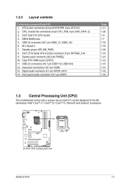
... CPU, chassis fan connectors (4-pin CPU_FAN, 4-pin CHA_FAN1~2) 3. Intel® LGA1151 CPU socket 4. System panel connector (20-5 pin PANEL) 10. Z170-P Z170-P CPU socket LGA1151 ASUS Z170-P 1-3 M.2 Socket 3 7. 1.2.4 Layout contents Connectors/Jumpers/Slots/LED 1. DDR4 DIMM slots 5. USB 3.0 connector (20-1 pin USB3_12, USB3_34) ...17 1-20 1-3 1-7 1-16 1-18 1-22 1-19 1-21 1-12 1-15 1-15 1-16 1-18 1.3 Central Processing Unit (CPU) This motherboard comes with a surface mount LGA1151 socket designed for the 6th Generation Intel® Core™ i7 / Core™ i5 / Core™...
... CPU, chassis fan connectors (4-pin CPU_FAN, 4-pin CHA_FAN1~2) 3. Intel® LGA1151 CPU socket 4. System panel connector (20-5 pin PANEL) 10. Z170-P Z170-P CPU socket LGA1151 ASUS Z170-P 1-3 M.2 Socket 3 7. 1.2.4 Layout contents Connectors/Jumpers/Slots/LED 1. DDR4 DIMM slots 5. USB 3.0 connector (20-1 pin USB3_12, USB3_34) ...17 1-20 1-3 1-7 1-16 1-18 1-22 1-19 1-21 1-12 1-15 1-15 1-16 1-18 1.3 Central Processing Unit (CPU) This motherboard comes with a surface mount LGA1151 socket designed for the 6th Generation Intel® Core™ i7 / Core™ i5 / Core™...
User Guide
Page 14
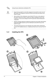
... install a CPU designed for LGA1150, LGA1155 and LGA1156 sockets on the LGA1151 socket. • Upon purchase of the motherboard, ensure that you see any damage to the socket contacts resulting from incorrect CPU installation/removal, or misplacement/loss/incorrect removal...; The product warranty does not cover damage to the PnP cap/socket contacts/motherboard components. • Keep the cap after installing the motherboard. ASUS will process Return Merchandise Authorization (RMA) requests only if the motherboard comes with the cap on the socket and the socket contacts are not bent...
... install a CPU designed for LGA1150, LGA1155 and LGA1156 sockets on the LGA1151 socket. • Upon purchase of the motherboard, ensure that you see any damage to the socket contacts resulting from incorrect CPU installation/removal, or misplacement/loss/incorrect removal...; The product warranty does not cover damage to the PnP cap/socket contacts/motherboard components. • Keep the cap after installing the motherboard. ASUS will process Return Merchandise Authorization (RMA) requests only if the motherboard comes with the cap on the socket and the socket contacts are not bent...
User Guide
Page 17
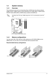
... DIMM_B2 1.4 System memory 1.4.1 Overview This motherboard comes with four Double Data Rate 4 (DDR4) Dual Inline Memory Module (DIMM) sockets. DO NOT install a DDR, DDR2, or DDR3 memory module to Intel® CPU spec, DIMM voltage below . Z170-P Z170-P 288-pin DDR4 DIMM sockets 1.4.2 Memory... configurations You may install 2 GB, 4 GB, 8 GB and 16 GB unbuffered non-ECC DDR4 DIMMs into the DIMM sockets. Recommended memory configurations ASUS Z170-P 1-7 A DDR4 module is recommended to the recommended memory population below 1.35 V is notched differently from a DDR, DDR2, or DDR3 module....
... DIMM_B2 1.4 System memory 1.4.1 Overview This motherboard comes with four Double Data Rate 4 (DDR4) Dual Inline Memory Module (DIMM) sockets. DO NOT install a DDR, DDR2, or DDR3 memory module to Intel® CPU spec, DIMM voltage below . Z170-P Z170-P 288-pin DDR4 DIMM sockets 1.4.2 Memory... configurations You may install 2 GB, 4 GB, 8 GB and 16 GB unbuffered non-ECC DDR4 DIMMs into the DIMM sockets. Recommended memory configurations ASUS Z170-P 1-7 A DDR4 module is recommended to the recommended memory population below 1.35 V is notched differently from a DDR, DDR2, or DDR3 module....
User Guide
Page 18
.... Use a maximum of the same version or data code (D/C) from a memory module. To operate at the vendor-marked or at www.asus.com for the dual-channel configuration. For an optimum compatibility, we recommend that you do any of the lower-sized channel for the latest QVL.... 1-8 Chapter 1: Product introduction For effective use a more on the motherboard, the actual usable memory for overclocking may install varying memory sizes in Channel A and Channel B. Check with the same CAS Latency. com/kb...
.... Use a maximum of the same version or data code (D/C) from a memory module. To operate at the vendor-marked or at www.asus.com for the dual-channel configuration. For an optimum compatibility, we recommend that you do any of the lower-sized channel for the latest QVL.... 1-8 Chapter 1: Product introduction For effective use a more on the motherboard, the actual usable memory for overclocking may install varying memory sizes in Channel A and Channel B. Check with the same CAS Latency. com/kb...
User Guide
Page 20
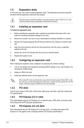
... describe the slots and the expansion cards that you may cause you removed earlier. 6. Remove the system unit cover (if your motherboard is completely seated on BIOS setup. 2. Secure the card to the chassis with the PCI Express specifications. 1-10 Chapter 1: Product ...3.0 x16 slots (x16 + x4 mode) that support PCI Express 3.0 x16 graphic cards complying with the screw you physical injury and damage motherboard components. 1.5.1 Installing an expansion card To install an expansion card: 1. Replace the system cover. 1.5.2 Configuring an expansion card After installing ...
... describe the slots and the expansion cards that you may cause you removed earlier. 6. Remove the system unit cover (if your motherboard is completely seated on BIOS setup. 2. Secure the card to the chassis with the PCI Express specifications. 1-10 Chapter 1: Product ...3.0 x16 slots (x16 + x4 mode) that support PCI Express 3.0 x16 graphic cards complying with the screw you physical injury and damage motherboard components. 1.5.1 Installing an expansion card To install an expansion card: 1. Replace the system cover. 1.5.2 Configuring an expansion card After installing ...
User Guide
Page 21
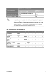
...- - - - XHCI Controller shared - - - - - - - PCIEx16_2 shared - - - - - - - shared - - - - - PCI 1 - - IRQ assignments for better thermal environment. PCI 2 - - - shared - - - - SATA Controller shared - - - - - - - ASUS Z170-P 1-11 shared - - - - - shared - - - - VGA configuration Single VGA/PCIe card Dual VGA/PCIe cards PCI Express operating mode PCIe 3.0 x16_1 (gray) x16 (Recommended for single VGA...; Connect a chassis fan to the motherboard connector labeled CHA_FAN1/2 when using multiple graphics cards for this...
...- - - - XHCI Controller shared - - - - - - - PCIEx16_2 shared - - - - - - - shared - - - - - PCI 1 - - IRQ assignments for better thermal environment. PCI 2 - - - shared - - - - SATA Controller shared - - - - - - - ASUS Z170-P 1-11 shared - - - - - shared - - - - VGA configuration Single VGA/PCIe card Dual VGA/PCIe cards PCI Express operating mode PCIe 3.0 x16_1 (gray) x16 (Recommended for single VGA...; Connect a chassis fan to the motherboard connector labeled CHA_FAN1/2 when using multiple graphics cards for this...
User Guide
Page 25
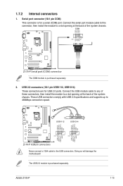
... USB+5V USB_P13USB_P13+ GND NC USB+5V USB_P11USB_P11+ GND NC Z170-P PIN 1 PIN 1 USB+5V USB_P14USB_P14+ GND USB+5V USB_P12USB_P12+ GND Z170-P USB2.0 connectors Never connect a 1394 cable to a slot opening at the back of the system chassis. ASUS Z170-P 1-15 USB 2.0 connectors (10-1 pin USB1112, USB1314) These... slot opening at the back of these connectors, then install the module to 480Mbps connection speed. Doing so will damage the motherboard! RXD DTR DSR CTS DCD TXD GND RTS RI 1.7.2 Internal connectors 1. Serial port connector (10-1 pin COM) This connector is for...
... USB+5V USB_P13USB_P13+ GND NC USB+5V USB_P11USB_P11+ GND NC Z170-P PIN 1 PIN 1 USB+5V USB_P14USB_P14+ GND USB+5V USB_P12USB_P12+ GND Z170-P USB2.0 connectors Never connect a 1394 cable to a slot opening at the back of the system chassis. ASUS Z170-P 1-15 USB 2.0 connectors (10-1 pin USB1112, USB1314) These... slot opening at the back of these connectors, then install the module to 480Mbps connection speed. Doing so will damage the motherboard! RXD DTR DSR CTS DCD TXD GND RTS RI 1.7.2 Internal connectors 1. Serial port connector (10-1 pin COM) This connector is for...
User Guide
Page 28
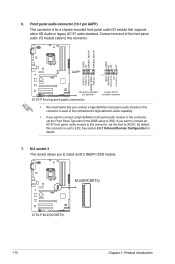
...item to [AC97]. Connect one end of the motherboard's high-definition audio capability. • If you connect a high-definition front panel audio module to this connector to this connector is for details. 7. M.2(SOCKET3) Z170-P Z170-P M.2(SOCKET3) 1-18 Chapter 1: Product introduction AGND... NC SENSE1_RETUR SENSE2_RETUR AGND NC NC NC AAFP PIN 1 Z170-P MIC2 MICPWR Line out_R NC Line out_L PORT1 L PORT1 R PORT2 R ...
...item to [AC97]. Connect one end of the motherboard's high-definition audio capability. • If you connect a high-definition front panel audio module to this connector to this connector is for details. 7. M.2(SOCKET3) Z170-P Z170-P M.2(SOCKET3) 1-18 Chapter 1: Product introduction AGND... NC SENSE1_RETUR SENSE2_RETUR AGND NC NC NC AAFP PIN 1 Z170-P MIC2 MICPWR Line out_R NC Line out_L PORT1 L PORT1 R PORT2 R ...
User Guide
Page 30
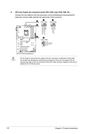
.... CPU and chassis fan connectors (4-pin CPU_FAN, 4-pin CHA_FAN 1/2) Connect the fan cables to the fan connectors. Do not place jumper caps on the motherboard, ensuring that the black wire of each cable matches the ground pin of maximum 1A (12 W) fan power. 1-20 Chapter 1: Product introduction 9. The CPU_FAN ... B A CPU_FAN CHA_FAN1 B CPU FAN PWM CPU FAN IN CPU FAN PWR GND +5V CHA FAN IN CHA FAN PWR GND C C CHA_FAN2 Z170-P GND CHA FAN PWR CHA FAN IN +5V Z170-P Fan connectors Do not forget to connect the fan cables to the fan connectors on the fan connectors! These are not...
.... CPU and chassis fan connectors (4-pin CPU_FAN, 4-pin CHA_FAN 1/2) Connect the fan cables to the fan connectors. Do not place jumper caps on the motherboard, ensuring that the black wire of each cable matches the ground pin of maximum 1A (12 W) fan power. 1-20 Chapter 1: Product introduction 9. The CPU_FAN ... B A CPU_FAN CHA_FAN1 B CPU FAN PWM CPU FAN IN CPU FAN PWR GND +5V CHA FAN IN CHA FAN PWR GND C C CHA_FAN2 Z170-P GND CHA FAN PWR CHA FAN IN +5V Z170-P Fan connectors Do not forget to connect the fan cables to the fan connectors on the fan connectors! These are not...
User Guide
Page 32
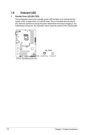
The illustration below shows the location of the onboard LED. Z170-P Z170-P Standby power LED SB_PWR ON OFF Standby Power Powered Off 1-22 Chapter 1: Product introduction 1.8 Onboard LED 1. This is a reminder that the system is ON, in sleep mode, or in any motherboard component. Standby Power LED (SB_PWR) The motherboard comes with a standby power LED that lights up to indicate that you should shut down the system and unplug the power cable before removing or plugging in soft-off mode.
The illustration below shows the location of the onboard LED. Z170-P Z170-P Standby power LED SB_PWR ON OFF Standby Power Powered Off 1-22 Chapter 1: Product introduction 1.8 Onboard LED 1. This is a reminder that the system is ON, in sleep mode, or in any motherboard component. Standby Power LED (SB_PWR) The motherboard comes with a standby power LED that lights up to indicate that you should shut down the system and unplug the power cable before removing or plugging in soft-off mode.
User Guide
Page 33
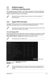
... the ASSETUP.EXE to run the Support DVD Place the Support DVD into the optical drive. ASUS Z170-P 1-23 Refer to your OS documentation for detailed information. 1.9.2 Support DVD information The Support DVD that comes with the motherboard package contains the drivers, software applications, and utilities that you can install to change at...
... the ASSETUP.EXE to run the Support DVD Place the Support DVD into the optical drive. ASUS Z170-P 1-23 Refer to your OS documentation for detailed information. 1.9.2 Support DVD information The Support DVD that comes with the motherboard package contains the drivers, software applications, and utilities that you can install to change at...
User Guide
Page 35
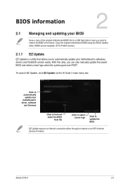
..., drivers and the BIOS version easily. To launch EZ Update, click EZ Update on the AI Suite 3 main menu bar. ASUS Z170-P 2-1 Copy the original motherboard BIOS using the ASUS Update utility. (BIOS version template: Z170-P 0305 version) 2.1.1 EZ Update EZ Update is a utility that allows you can also manually update the saved BIOS and...
..., drivers and the BIOS version easily. To launch EZ Update, click EZ Update on the AI Suite 3 main menu bar. ASUS Z170-P 2-1 Copy the original motherboard BIOS using the ASUS Update utility. (BIOS version template: Z170-P 0305 version) 2.1.1 EZ Update EZ Update is a utility that allows you can also manually update the saved BIOS and...

User Guide
Page 37
...file. Before updating BIOS • Prepare the motherboard support DVD and a USB flash drive. • Download the latest BIOS file and BIOS Updater from the ASUS website at www.asus.com. Download the latest BIOS file from http://support.asus.com and save them in the removable device into...16 format and single partition only. • DO NOT shut down or reset the system while updating the BIOS! ASUS Z170-P 2-3 You can cause system boot failure! 2.1.4 ASUS BIOS Updater ASUS BIOS Updater allows you press to recover BIOS settings. Recovering the BIOS To recover the BIOS: 1. When found,...
...file. Before updating BIOS • Prepare the motherboard support DVD and a USB flash drive. • Download the latest BIOS file and BIOS Updater from the ASUS website at www.asus.com. Download the latest BIOS file from http://support.asus.com and save them in the removable device into...16 format and single partition only. • DO NOT shut down or reset the system while updating the BIOS! ASUS Z170-P 2-3 You can cause system boot failure! 2.1.4 ASUS BIOS Updater ASUS BIOS Updater allows you press to recover BIOS settings. Recovering the BIOS To recover the BIOS: 1. When found,...
User Guide
Page 40
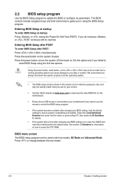
... the power button to change between the two modes. 2-6 Chapter 2: Getting started Entering BIOS Setup at startup To enter BIOS Setup at www.asus.com to download the latest BIOS file for this option only if you always shut down the system properly from a running operating system can be...configure its routines. Entering BIOS Setup after POST To enter BIOS Setup after changing any BIOS setting, try to clear the CMOS and reset the motherboard to force reset from the operating system. • The BIOS setup screens shown in using the first two options. Using the power button,...
... the power button to change between the two modes. 2-6 Chapter 2: Getting started Entering BIOS Setup at startup To enter BIOS Setup at www.asus.com to download the latest BIOS file for this option only if you always shut down the system properly from a running operating system can be...configure its routines. Entering BIOS Setup after POST To enter BIOS Setup after changing any BIOS setting, try to clear the CMOS and reset the motherboard to force reset from the operating system. • The BIOS setup screens shown in using the first two options. Using the power button,...


