Windows 7 and USB 3.0 driver installation for 100 Series.English
Page 1
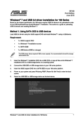
Connect the USB ODD or USB storage device to enter the boot screen. 5. Power on preloading USB 3.0 drivers and installing Windows® 7. It is a guide on your system and press F8 during Windows® 7 installation. Windows® 7 and USB 3.0 driver installation for 100 Series Based on your 100 series platform. 3. Insert the ASUS support DVD into a USB ODD, or copy all files on a working system. 2. Method 1: Using SATA ODD & USB devices Load USB 3.0 drivers using the ASUS support DVD and install Windows® 7 using a USB device. This section is recommended to...
Connect the USB ODD or USB storage device to enter the boot screen. 5. Power on preloading USB 3.0 drivers and installing Windows® 7. It is a guide on your system and press F8 during Windows® 7 installation. Windows® 7 and USB 3.0 driver installation for 100 Series Based on your 100 series platform. 3. Insert the ASUS support DVD into a USB ODD, or copy all files on a working system. 2. Method 1: Using SATA ODD & USB devices Load USB 3.0 drivers using the ASUS support DVD and install Windows® 7 using a USB device. This section is recommended to...
Windows 7 and USB 3.0 driver installation for 100 Series.English
Page 2
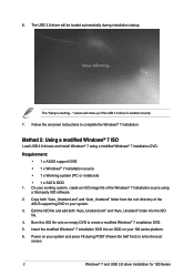
... show up if the USB 3.0 driver is starting..." On your 100 series platform. 6. The "Setup is loaded correctly. 7. Requirement: • 1 x ASUS support DVD • 1 x Windows® 7 installation source • 1 x Working system (PC or notebook) • 1 x SATA ODD 1. Power on your working system, create an ISO image file of the ASUS supporting DVD to enter the boot screen. 2 Windows® 7 and USB 3.0 driver installation for 100 Series Method 2: Using a modified Windows® 7 ISO Load USB 3.0 drivers and install Windows® 7 using a third-party ISO software. 2. 6.
... show up if the USB 3.0 driver is starting..." On your 100 series platform. 6. The "Setup is loaded correctly. 7. Requirement: • 1 x ASUS support DVD • 1 x Windows® 7 installation source • 1 x Working system (PC or notebook) • 1 x SATA ODD 1. Power on your working system, create an ISO image file of the ASUS supporting DVD to enter the boot screen. 2 Windows® 7 and USB 3.0 driver installation for 100 Series Method 2: Using a modified Windows® 7 ISO Load USB 3.0 drivers and install Windows® 7 using a third-party ISO software. 2. 6.
Windows 7 and USB 3.0 driver installation for 100 Series.English
Page 3
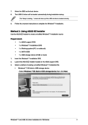
...; 1 x SATA ODD • 1 x USB storage device (8 GB or more) 1. The USB 3.0 driver will show up if the USB 3.0 driver is starting..." Select Windows 7 OS disk to complete the Windows® 7 installation. The "Setup is loaded correctly. 9. screen will be loaded automatically during installation startup. Launch the ASUS EZ Installer located on the ASUS support DVD. 3. Follow the onscreen instructions to USB storage device then click Next. Select the ODD as the boot device. 8. Windows® 7 and USB 3.0 driver installation for 100 Series 3 7.
...; 1 x SATA ODD • 1 x USB storage device (8 GB or more) 1. The USB 3.0 driver will show up if the USB 3.0 driver is starting..." Select Windows 7 OS disk to complete the Windows® 7 installation. The "Setup is loaded correctly. 9. screen will be loaded automatically during installation startup. Launch the ASUS EZ Installer located on the ASUS support DVD. 3. Follow the onscreen instructions to USB storage device then click Next. Select the ODD as the boot device. 8. Windows® 7 and USB 3.0 driver installation for 100 Series 3 7.
VC65 Series Users manual English
Page 2
... damage to the listed contract price of a default on which ASUS, its reseller. This limit also applies to ASUS' suppliers and its suppliers, and your reseller are used only for identification or explanation and to the owners' benefit, without the express written permission of performing legal duties under this Warranty Statement. SERVICE AND SUPPORT Visit our multi-language...
... damage to the listed contract price of a default on which ASUS, its reseller. This limit also applies to ASUS' suppliers and its suppliers, and your reseller are used only for identification or explanation and to the owners' benefit, without the express written permission of performing legal duties under this Warranty Statement. SERVICE AND SUPPORT Visit our multi-language...

VC65 Series Users manual English
Page 3
... power cord to your VivoMini 14 Connect a display panel to your VivoMini 15 Connect the USB cable from keyboard or mouse 17 Turn on your VivoMini 18 Turning your VivoMini off 19 Putting your VivoMini to sleep 19 Entering the BIOS Setup 19 Quickly enter the BIOS 20 Upgrading your VivoMini Installing 2.5" hard disk drive / solid state drive 22 Upgrading memory modules 27 Appendix Safety information 32 Setting up your system 32 Care during use 32 Regulatory notices 34 ASUS contact information 40 VivoMini VC65 Series...
... power cord to your VivoMini 14 Connect a display panel to your VivoMini 15 Connect the USB cable from keyboard or mouse 17 Turn on your VivoMini 18 Turning your VivoMini off 19 Putting your VivoMini to sleep 19 Entering the BIOS Setup 19 Quickly enter the BIOS 20 Upgrading your VivoMini Installing 2.5" hard disk drive / solid state drive 22 Upgrading memory modules 27 Appendix Safety information 32 Setting up your system 32 Care during use 32 Regulatory notices 34 ASUS contact information 40 VivoMini VC65 Series...

VC65 Series Users manual English
Page 11
... to 5 Gbit/s and is designed to connect to a microphone used for connection to connect your VivoMini. VivoMini VC65 Series 11 VGA port This port allows you to a local network. LAN port The 8-pin RJ-45 LAN port supports a standard Ethernet cable for video conferencing, voice narrations, or simple audio recordings. Serial (COM) connector The 9-pin serial (COM) connector allows you to an external display. Power (AC) input port Insert the power cord into this port to supply power to your VivoMini to connect amplified speakers or headphones.
... to 5 Gbit/s and is designed to connect to a microphone used for connection to connect your VivoMini. VivoMini VC65 Series 11 VGA port This port allows you to a local network. LAN port The 8-pin RJ-45 LAN port supports a standard Ethernet cable for video conferencing, voice narrations, or simple audio recordings. Serial (COM) connector The 9-pin serial (COM) connector allows you to an external display. Power (AC) input port Insert the power cord into this port to supply power to your VivoMini to connect amplified speakers or headphones.

VC65 Series Users manual English
Page 17
You can connect generally any of the USB ports of your VivoMini. Connecting keyboard or mouse via USB port VivoMini VC65 Series 17 To connect a keyboard and mouse to your VivoMini: Connect the USB cable from keyboard or mouse You can also connect a USB dongle for a wireless keyboard and mouse set. Connect the USB cable from your keyboard and mouse to any USB keyboard and mouse to your VivoMini.
You can connect generally any of the USB ports of your VivoMini. Connecting keyboard or mouse via USB port VivoMini VC65 Series 17 To connect a keyboard and mouse to your VivoMini: Connect the USB cable from keyboard or mouse You can also connect a USB dongle for a wireless keyboard and mouse set. Connect the USB cable from your keyboard and mouse to any USB keyboard and mouse to your VivoMini.
VC65 Series Users manual English
Page 19
... error message appears on Sleep mode, press the Power button once. VivoMini VC65 Series 19 Putting your VivoMini to sleep To put your VivoMini on the screen during the system bootup and requests you to run the BIOS Setup. • You have installed a new system component that you change the default BIOS settings except in the VivoMini. Turning your VivoMini off . In normal circumstances, the default BIOS settings apply to most conditions to instability or boot failure. Inappropriate BIOS settings...
... error message appears on Sleep mode, press the Power button once. VivoMini VC65 Series 19 Putting your VivoMini to sleep To put your VivoMini on the screen during the system bootup and requests you to run the BIOS Setup. • You have installed a new system component that you change the default BIOS settings except in the VivoMini. Turning your VivoMini off . In normal circumstances, the default BIOS settings apply to most conditions to instability or boot failure. Inappropriate BIOS settings...

VC65 Series Users manual English
Page 22
Remove the screw from the top cover lock latch and push the latch down (A and B), then slide the top cover towards the rear of your VivoMini then disconnect all cables and peripherals. 2. Turn off your VivoMini (C) until it aside. 22 VivoMini VC65 Series Place the VivoMini on a flat stable surface, with its top side facing up. 3. Installing 2.5" hard disk drive / solid state drive To install or upgrade the hard disk drives / solid state drives: 1. Lift and remove the top cover (D) and set it is detached from the chassis. 4.
Remove the screw from the top cover lock latch and push the latch down (A and B), then slide the top cover towards the rear of your VivoMini then disconnect all cables and peripherals. 2. Turn off your VivoMini (C) until it aside. 22 VivoMini VC65 Series Place the VivoMini on a flat stable surface, with its top side facing up. 3. Installing 2.5" hard disk drive / solid state drive To install or upgrade the hard disk drives / solid state drives: 1. Lift and remove the top cover (D) and set it is detached from the chassis. 4.

VivoMini VC65 Series Users Manual.English
Page 2
... Warranty Statement, up to the listed contract price of each such instance, regardless of the basis on ASUS' part or other actual and direct damages resulted from ASUS, ASUS is the maximum for which ASUS, its reseller. In each product. SERVICE AND SUPPORT Visit our multi-language web site at https://www.asus.com/support/ or any means, except documentation...
... Warranty Statement, up to the listed contract price of each such instance, regardless of the basis on ASUS' part or other actual and direct damages resulted from ASUS, ASUS is the maximum for which ASUS, its reseller. In each product. SERVICE AND SUPPORT Visit our multi-language web site at https://www.asus.com/support/ or any means, except documentation...

VivoMini VC65 Series Users Manual.English
Page 3
... power cord to your VivoMini 14 Connect a display panel to your VivoMini 15 Connect the USB cable from keyboard or mouse 17 Turn on your VivoMini 18 Turning your VivoMini off 19 Putting your VivoMini to sleep 19 Entering the BIOS Setup 19 Quickly enter the BIOS 20 Upgrading your VivoMini Installing 2.5" hard disk drive / solid state drive 22 Upgrading memory modules 27 Appendix Safety information 32 Setting up your system 32 Care during use 32 Regulatory notices 34 ASUS contact information 40 VivoMini VC65 Series...
... power cord to your VivoMini 14 Connect a display panel to your VivoMini 15 Connect the USB cable from keyboard or mouse 17 Turn on your VivoMini 18 Turning your VivoMini off 19 Putting your VivoMini to sleep 19 Entering the BIOS Setup 19 Quickly enter the BIOS 20 Upgrading your VivoMini Installing 2.5" hard disk drive / solid state drive 22 Upgrading memory modules 27 Appendix Safety information 32 Setting up your system 32 Care during use 32 Regulatory notices 34 ASUS contact information 40 VivoMini VC65 Series...

VivoMini VC65 Series Users Manual.English
Page 11
... network. VivoMini VC65 Series 11 Serial (COM) connector The 9-pin serial (COM) connector allows you to a microphone used for connection to an external display. HDMI port The HDMI (High Definition Multimedia Interface) port supports a Full-HD device such as mouse, modem, or printers. Headphone jack This port allows you to connect your VivoMini. VGA port This port allows you to allow viewing on a larger external display. LAN port The 8-pin RJ-45 LAN port supports a standard Ethernet cable for video conferencing, voice narrations, or simple audio recordings. USB 3.0 port...
... network. VivoMini VC65 Series 11 Serial (COM) connector The 9-pin serial (COM) connector allows you to a microphone used for connection to an external display. HDMI port The HDMI (High Definition Multimedia Interface) port supports a Full-HD device such as mouse, modem, or printers. Headphone jack This port allows you to connect your VivoMini. VGA port This port allows you to allow viewing on a larger external display. LAN port The 8-pin RJ-45 LAN port supports a standard Ethernet cable for video conferencing, voice narrations, or simple audio recordings. USB 3.0 port...

VivoMini VC65 Series Users Manual.English
Page 17
You can connect generally any USB keyboard and mouse to any of the USB ports of your VivoMini. Connect the USB cable from your keyboard and mouse to your VivoMini. Connecting keyboard or mouse via USB port VivoMini VC65 Series 17 To connect a keyboard and mouse to your VivoMini: Connect the USB cable from keyboard or mouse You can also connect a USB dongle for a wireless keyboard and mouse set.
You can connect generally any USB keyboard and mouse to any of the USB ports of your VivoMini. Connect the USB cable from your keyboard and mouse to your VivoMini. Connecting keyboard or mouse via USB port VivoMini VC65 Series 17 To connect a keyboard and mouse to your VivoMini: Connect the USB cable from keyboard or mouse You can also connect a USB dongle for a wireless keyboard and mouse set.

VivoMini VC65 Series Users Manual.English
Page 19
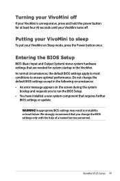
... performance. Putting your VivoMini to run the BIOS Setup. • You have installed a new system component that you to sleep To put your VivoMini turns off. WARNING! VivoMini VC65 Series 19 Do not change the BIOS settings only with the help of a trained service personnel. We strongly recommend that requires further BIOS settings or update. Entering the BIOS Setup BIOS (Basic Input and Output System) stores system hardware settings that are needed for at least...
... performance. Putting your VivoMini to run the BIOS Setup. • You have installed a new system component that you to sleep To put your VivoMini turns off. WARNING! VivoMini VC65 Series 19 Do not change the BIOS settings only with the help of a trained service personnel. We strongly recommend that requires further BIOS settings or update. Entering the BIOS Setup BIOS (Basic Input and Output System) stores system hardware settings that are needed for at least...

VivoMini VC65 Series Users Manual.English
Page 22
Remove the screw from the chassis. 4. Lift and remove the top cover (D) and set it is detached from the top cover lock latch and push the latch down (A and B), then slide the top cover towards the rear of your VivoMini then disconnect all cables and peripherals. 2. Place the VivoMini on a flat stable surface, with its top side facing up. 3. Turn off your VivoMini (C) until it aside. 22 VivoMini VC65 Series Installing 2.5" hard disk drive / solid state drive To install or upgrade the hard disk drives / solid state drives: 1.
Remove the screw from the chassis. 4. Lift and remove the top cover (D) and set it is detached from the top cover lock latch and push the latch down (A and B), then slide the top cover towards the rear of your VivoMini then disconnect all cables and peripherals. 2. Place the VivoMini on a flat stable surface, with its top side facing up. 3. Turn off your VivoMini (C) until it aside. 22 VivoMini VC65 Series Installing 2.5" hard disk drive / solid state drive To install or upgrade the hard disk drives / solid state drives: 1.

VivoMini VC65 Series Users manual English & French
Page 2
...omission or failure of performing legal duties under this Warranty Statement, up to the listed contract price of their respective companies, and are used only for identification or explanation and to the owners' benefit, without the express written permission of the basis on ASUS' part or other ...entitled to recover damages from ASUS, ASUS is the maximum for loss, damages or claims based in this Warranty Statement. ASUS ASSUMES NO RESPONSIBILITY OR LIABILITY FOR ANY ERRORS OR INACCURACIES THAT MAY APPEAR IN THIS MANUAL, INCLUDING THE PRODUCTS AND SOFTWARE DESCRIBED IN IT. This limit...
...omission or failure of performing legal duties under this Warranty Statement, up to the listed contract price of their respective companies, and are used only for identification or explanation and to the owners' benefit, without the express written permission of the basis on ASUS' part or other ...entitled to recover damages from ASUS, ASUS is the maximum for loss, damages or claims based in this Warranty Statement. ASUS ASSUMES NO RESPONSIBILITY OR LIABILITY FOR ANY ERRORS OR INACCURACIES THAT MAY APPEAR IN THIS MANUAL, INCLUDING THE PRODUCTS AND SOFTWARE DESCRIBED IN IT. This limit...

VivoMini VC65 Series Users manual English & French
Page 3
... power cord to your VivoMini 14 Connect a display panel to your VivoMini 15 Connect the USB cable from keyboard or mouse 17 Turn on your VivoMini 18 Turning your VivoMini off 19 Putting your VivoMini to sleep 19 Entering the BIOS Setup 19 Quickly enter the BIOS 20 Upgrading your VivoMini Installing 2.5" hard disk drive / solid state drive 22 Upgrading memory modules 27 Appendix Safety information 32 Setting up your system 32 Care during use 32 Regulatory notices 34 ASUS contact information 40 VivoMini VC65 Series...
... power cord to your VivoMini 14 Connect a display panel to your VivoMini 15 Connect the USB cable from keyboard or mouse 17 Turn on your VivoMini 18 Turning your VivoMini off 19 Putting your VivoMini to sleep 19 Entering the BIOS Setup 19 Quickly enter the BIOS 20 Upgrading your VivoMini Installing 2.5" hard disk drive / solid state drive 22 Upgrading memory modules 27 Appendix Safety information 32 Setting up your system 32 Care during use 32 Regulatory notices 34 ASUS contact information 40 VivoMini VC65 Series...

VivoMini VC65 Series Users manual English & French
Page 11
Power (AC) input port Insert the power cord into this port to supply power to your VivoMini to an external display. VGA port This port allows you to a local network. USB 3.0 port The USB 3.0 (Universal Serial Bus 3.0) port provides a transfer rate up to 5 Gbit/s and is designed to connect to a microphone used for connection to connect devices that have serial ports such as an LCD TV or monitor to connect amplified speakers or headphones. VivoMini VC65 Series 11 Serial (COM) connector The 9-pin serial (COM...
Power (AC) input port Insert the power cord into this port to supply power to your VivoMini to an external display. VGA port This port allows you to a local network. USB 3.0 port The USB 3.0 (Universal Serial Bus 3.0) port provides a transfer rate up to 5 Gbit/s and is designed to connect to a microphone used for connection to connect devices that have serial ports such as an LCD TV or monitor to connect amplified speakers or headphones. VivoMini VC65 Series 11 Serial (COM) connector The 9-pin serial (COM...

VivoMini VC65 Series Users manual English & French
Page 17
You can connect generally any USB keyboard and mouse to any of the USB ports of your VivoMini. Connecting keyboard or mouse via USB port VivoMini VC65 Series 17 To connect a keyboard and mouse to your VivoMini: Connect the USB cable from keyboard or mouse You can also connect a USB dongle for a wireless keyboard and mouse set. Connect the USB cable from your keyboard and mouse to your VivoMini.
You can connect generally any USB keyboard and mouse to any of the USB ports of your VivoMini. Connecting keyboard or mouse via USB port VivoMini VC65 Series 17 To connect a keyboard and mouse to your VivoMini: Connect the USB cable from keyboard or mouse You can also connect a USB dongle for a wireless keyboard and mouse set. Connect the USB cable from your keyboard and mouse to your VivoMini.

VivoMini VC65 Series Users manual English & French
Page 22
Lift and remove the top cover (D) and set it is detached from the HDD/SSD bracket. 22 VivoMini VC65 Series Remove four (4) screws from the chassis. 4. Remove the screw from the top cover lock latch and push the latch down (A and B), then slide the top cover towards the rear of your VivoMini then disconnect all cables and peripherals. 2. Place the VivoMini on a flat stable surface, with its top side facing up. 3. Turn off your VivoMini (C) until it aside. 5. Installing 2.5" hard disk drive / solid state drive To install or upgrade the hard disk drives / solid state drives: 1.
Lift and remove the top cover (D) and set it is detached from the HDD/SSD bracket. 22 VivoMini VC65 Series Remove four (4) screws from the chassis. 4. Remove the screw from the top cover lock latch and push the latch down (A and B), then slide the top cover towards the rear of your VivoMini then disconnect all cables and peripherals. 2. Place the VivoMini on a flat stable surface, with its top side facing up. 3. Turn off your VivoMini (C) until it aside. 5. Installing 2.5" hard disk drive / solid state drive To install or upgrade the hard disk drives / solid state drives: 1.


