UN65U Users ManualEnglish
Page 3
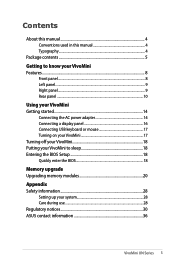
... 14 Connecting a display panel 16 Connecting USB keyboard or mouse 17 Turning on your VivoMini 17 Turning off your VivoMini 18 Putting your VivoMini to sleep 18 Entering the BIOS Setup 18 Quickly enter the BIOS 18 Memory upgrade Upgrading memory modules 20 Appendix Safety information 28 Setting up your system 28 Care during use...
... 14 Connecting a display panel 16 Connecting USB keyboard or mouse 17 Turning on your VivoMini 17 Turning off your VivoMini 18 Putting your VivoMini to sleep 18 Entering the BIOS Setup 18 Quickly enter the BIOS 18 Memory upgrade Upgrading memory modules 20 Appendix Safety information 28 Setting up your system 28 Care during use...
UN65U Users ManualEnglish
Page 4
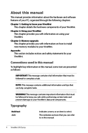
... tasks. This message contains important information that must be followed to your VivoMini's data and components. This indicates sections that can refer to know your VivoMini This chapter details the hardware components of your PC, organized through the ...VivoMini. Appendix This section includes notices and safety statements for your VivoMini. Chapter 2: Using your VivoMini. WARNING! Typography Bold text Italic Indicates a menu or an item to your VivoMini This chapter provides you with information on how to install new memory modules to select. Chapter 3: Memory...
... tasks. This message contains important information that must be followed to your VivoMini's data and components. This indicates sections that can refer to know your VivoMini This chapter details the hardware components of your PC, organized through the ...VivoMini. Appendix This section includes notices and safety statements for your VivoMini. Chapter 2: Using your VivoMini. WARNING! Typography Bold text Italic Indicates a menu or an item to your VivoMini This chapter provides you with information on how to install new memory modules to select. Chapter 3: Memory...
UN65U Users ManualEnglish
Page 9
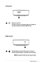
Left panel Memory card slot The built-in memory card reader enables your VivoMini to read and write data to secure your VivoMini using Kensington® compatible security products. VivoMini UN Series 9 Right panel The Kensington security slot allows you to and from MMC/SD cards. NOTE: The position for this slot may vary per model.
Left panel Memory card slot The built-in memory card reader enables your VivoMini to read and write data to secure your VivoMini using Kensington® compatible security products. VivoMini UN Series 9 Right panel The Kensington security slot allows you to and from MMC/SD cards. NOTE: The position for this slot may vary per model.
UN65U Users ManualEnglish
Page 20
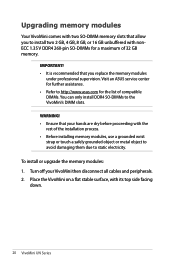
...• Refer to http://www.asus.com for a maximum of the installation process. • Before installing memory modules, use a grounded wrist strap or touch a safely grounded object or metal object to avoid damaging them due to the VivoMini's DIMM slots. Place the VivoMini on a flat stable surface, ... only install DDR4 SO-DIMMs to static electricity. WARNING! • Ensure that your VivoMini then disconnect all cables and peripherals. 2. Turn off your hands are dry before proceeding with the rest of 32 GB memory. IMPORTANT! • It is recommended that you to install two 2 GB, ...
...• Refer to http://www.asus.com for a maximum of the installation process. • Before installing memory modules, use a grounded wrist strap or touch a safely grounded object or metal object to avoid damaging them due to the VivoMini's DIMM slots. Place the VivoMini on a flat stable surface, ... only install DDR4 SO-DIMMs to static electricity. WARNING! • Ensure that your VivoMini then disconnect all cables and peripherals. 2. Turn off your hands are dry before proceeding with the rest of 32 GB memory. IMPORTANT! • It is recommended that you to install two 2 GB, ...

UN65U Users ManualEnglish
Page 24
Remove the screw you previously attached on the bottom cover (A), then align and insert the bottom cover back on your VivoMini (B) 24 VivoMini UN Series IMPORTANT! 7. Align and insert the memory module into the lower slot first. 8. Repeat the same steps to install the other memory module. Always install into the slot (A) and press it down (B) until it is securely seated in place.
Remove the screw you previously attached on the bottom cover (A), then align and insert the bottom cover back on your VivoMini (B) 24 VivoMini UN Series IMPORTANT! 7. Align and insert the memory module into the lower slot first. 8. Repeat the same steps to install the other memory module. Always install into the slot (A) and press it down (B) until it is securely seated in place.

