
Vintage-PE1 User''s Manual for English Edition
Page 7
...from the system, ensure that came with the package. • Before using the product, make sure all the documentation that the power cables for the devices are unplugged before the signal cables are not damaged. Do not place the product in any damage, contact your... the system, carefully read all cables are correctly connected and the power cables are connected. • If the power supply is incorrectly replaced. Safety information Electrical safety • To prevent electrical shock hazard, disconnect the power cable from the electrical outlet before relocating the system. • ...
...from the system, ensure that came with the package. • Before using the product, make sure all the documentation that the power cables for the devices are unplugged before the signal cables are not damaged. Do not place the product in any damage, contact your... the system, carefully read all cables are correctly connected and the power cables are connected. • If the power supply is incorrectly replaced. Safety information Electrical safety • To prevent electrical shock hazard, disconnect the power cable from the electrical outlet before relocating the system. • ...
Vintage-PE1 User''s Manual for English Edition
Page 10
Cable • AC power cable 3 . Support CD 4 . System package contents Check your Vintage-PE1 system package for the following items. If any of the items is damaged or missing, contact your retailer immediately. Item description 1 . P E 1 b a r e b o n e s y s t e m with • ASUS motherboard • 300 W power supply unit w/ PFC • ASUS chassis 2. User guide x A S U S V i n t a g e -
Cable • AC power cable 3 . Support CD 4 . System package contents Check your Vintage-PE1 system package for the following items. If any of the items is damaged or missing, contact your retailer immediately. Item description 1 . P E 1 b a r e b o n e s y s t e m with • ASUS motherboard • 300 W power supply unit w/ PFC • ASUS chassis 2. User guide x A S U S V i n t a g e -
Vintage-PE1 User''s Manual for English Edition
Page 15
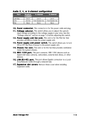
... is for the fan that provides ventilation inside the system chassis. 1 5 . I E E E 1 3 9 4 p o r t . ASUS Vintage-PE1 1-5 This vent is for the power cable and plug. 1 1 . This port allows Gigabit connection to the power supply unit. 1 4 . E x p a n s i o n s l o t c o v e r s. This connector is for the PSU fan that provides ventilation inside the power supply unit. 1 3 . Remove these cover when installing expansion cards. L A N ( R J - 4 5 ) p o r t . V o l t a g e s e l e c t o r . This switch allows...
... is for the fan that provides ventilation inside the system chassis. 1 5 . I E E E 1 3 9 4 p o r t . ASUS Vintage-PE1 1-5 This vent is for the power cable and plug. 1 1 . This port allows Gigabit connection to the power supply unit. 1 4 . E x p a n s i o n s l o t c o v e r s. This connector is for the PSU fan that provides ventilation inside the power supply unit. 1 3 . Remove these cover when installing expansion cards. L A N ( R J - 4 5 ) p o r t . V o l t a g e s e l e c t o r . This switch allows...

Vintage-PE1 User''s Manual for English Edition
Page 17
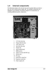
AGP 8X slot 10. Power supply unit ASUS Vintage-PE1 1-7 Front panel cover 4. PCI slots 11. 1.4 Internal components The illustration below is the internal view of the system when you remove the top cover and the power supply unit. Expansion card slots 13. Chassis fan 6. LGA775 socket with PnP cap 9. Floppy disk drive bay 3. Serial ATA connectors 12...
AGP 8X slot 10. Power supply unit ASUS Vintage-PE1 1-7 Front panel cover 4. PCI slots 11. 1.4 Internal components The illustration below is the internal view of the system when you remove the top cover and the power supply unit. Expansion card slots 13. Chassis fan 6. LGA775 socket with PnP cap 9. Floppy disk drive bay 3. Serial ATA connectors 12...

Vintage-PE1 User''s Manual for English Edition
Page 23
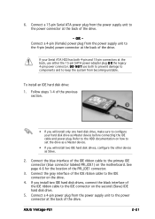
Connect one end of the IDE ribbon cable to pin 1 Power cable 8. ASUS Vintage-PE1 2-19 5. Audio cable IDE ribbon cable Red stripe to the IDE interface at the back of the optical drive. See page 4-9 for the location of ... at the back of the optical drive, matching the red stripe on the cable with Pin 1 on the IDE interface. 7. Connect a power cable from the power supply to the secondary IDE connector (labeled SEC_IDE1) on the motherboard. See page 4-5 for the location of this connector. Connect one end of the audio cable ...
Connect one end of the IDE ribbon cable to pin 1 Power cable 8. ASUS Vintage-PE1 2-19 5. Audio cable IDE ribbon cable Red stripe to the IDE interface at the back of the optical drive. See page 4-9 for the location of ... at the back of the optical drive, matching the red stripe on the cable with Pin 1 on the IDE interface. 7. Connect a power cable from the power supply to the secondary IDE connector (labeled SEC_IDE1) on the motherboard. See page 4-5 for the location of this connector. Connect one end of the audio cable ...

Vintage-PE1 User''s Manual for English Edition
Page 25
...See page 4-6 for the location of the drive. If your hard disk drive as Slave. 2. OR Connect a 4-pin (female) power plug from the power supply unit to the power connector at the back, use both 4-pin and 15-pin connectors at the back of the PRI_IDE1 connector. 3. Follow steps 1-4 of... the gray interface of the IDE ribbon cable to the IDE connector on the motherboard. Connect a 4-pin power plug from the power supply unit to configure your Serial ATA HDD has both to prevent damage to components and to the power connector at the back of the drive. ASUS Vintage-PE1 2-21
...See page 4-6 for the location of the drive. If your hard disk drive as Slave. 2. OR Connect a 4-pin (female) power plug from the power supply unit to the power connector at the back, use both 4-pin and 15-pin connectors at the back of the PRI_IDE1 connector. 3. Follow steps 1-4 of... the gray interface of the IDE ribbon cable to the IDE connector on the motherboard. Connect a 4-pin power plug from the power supply unit to configure your Serial ATA HDD has both to prevent damage to components and to the power connector at the back of the drive. ASUS Vintage-PE1 2-21
Vintage-PE1 User''s Manual for English Edition
Page 26
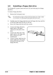
Connect the floppy disk drive signal cable to the power connector at the back of the drive. 5. For instructions on how to remove the front panel cover, refer to the floppy disk drive connector on ... to page 2-3 of the floppy disk drive. 6 4 2-22 Chapter 2: Basic installation Connect a power cable from the power supply unit to the signal connector at the back of section "2.3 Removing the side plates and front cover" 2. 2.9 Installing a floppy disk drive The Vintage-PE1 system comes with the holes on the motherboard. 6. To install a floppy disk drive...
Connect the floppy disk drive signal cable to the power connector at the back of the drive. 5. For instructions on how to remove the front panel cover, refer to the floppy disk drive connector on ... to page 2-3 of the floppy disk drive. 6 4 2-22 Chapter 2: Basic installation Connect a power cable from the power supply unit to the signal connector at the back of section "2.3 Removing the side plates and front cover" 2. 2.9 Installing a floppy disk drive The Vintage-PE1 system comes with the holes on the motherboard. 6. To install a floppy disk drive...
Vintage-PE1 User''s Manual for English Edition
Page 40
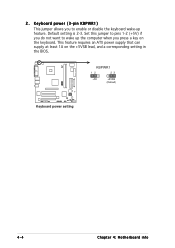
Default setting is 2-3. 2. Keyboard power (3-pin KBPWR1) This jumper allows you to enable or disable the keyboard wake-up the computer when you do not want to pins 1-2 (+5V) if you press a key on the +5VSB lead, and a corresponding setting in the BIOS. KBPWR1 12 23 +5V +5VSB (Default) ® Keyboard power setting 4-4 Chapter 4: Motherboard info Set this jumper to wake up feature. This feature requires an ATX power supply that can supply at least 1A on the keyboard.
Default setting is 2-3. 2. Keyboard power (3-pin KBPWR1) This jumper allows you to enable or disable the keyboard wake-up the computer when you do not want to pins 1-2 (+5V) if you press a key on the +5VSB lead, and a corresponding setting in the BIOS. KBPWR1 12 23 +5V +5VSB (Default) ® Keyboard power setting 4-4 Chapter 4: Motherboard info Set this jumper to wake up feature. This feature requires an ATX power supply that can supply at least 1A on the keyboard.
Vintage-PE1 User''s Manual for English Edition
Page 44
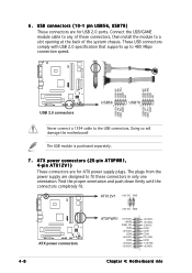
...3VDC +3.3VDC +5.0VDC +5.0VDC -5.0VDC COM COM COM PS_ON# COM -12.0VDC +3.3VDC 4-8 Chapter 4: Motherboard info The plugs from the power supply are for ATX power supply plugs. USB+5V USB_P8USB_P8+ GND NC USB+5V USB_P6USB_P6+ GND NC ® ® USB+5V USB_P7USB_P7+ GND USB+5V USB_P5USB_P5+ ...GND USB 2.0 connectors USB56 1 USB78 1 Never connect a 1394 cable to 480 Mbps connection speed. ATX power connectors (20-pin ATXPWR1, 4-pin ...
...3VDC +3.3VDC +5.0VDC +5.0VDC -5.0VDC COM COM COM PS_ON# COM -12.0VDC +3.3VDC 4-8 Chapter 4: Motherboard info The plugs from the power supply are for ATX power supply plugs. USB+5V USB_P8USB_P8+ GND NC USB+5V USB_P6USB_P6+ GND NC ® ® USB+5V USB_P7USB_P7+ GND USB+5V USB_P5USB_P5+ ...GND USB 2.0 connectors USB56 1 USB78 1 Never connect a 1394 cable to 480 Mbps connection speed. ATX power connectors (20-pin ATXPWR1, 4-pin ...
Vintage-PE1 User''s Manual for English Edition
Page 76
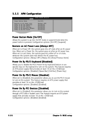
...to turn on the system. This feature requires an ATX power supply that provides at least 1A on the +5VSB lead. This feature requires an ATX power supply that provides at least 1A on the +5VSB lead. This feature requires an ATX power supply that provides at least 1A on the +5VSB lead.... Configuration options: [Disabled] [Space Bar] [Ctrl-Esc] [Power Key] Power On By PS/2 Mouse [Disabled] When set to...
...to turn on the system. This feature requires an ATX power supply that provides at least 1A on the +5VSB lead. This feature requires an ATX power supply that provides at least 1A on the +5VSB lead. This feature requires an ATX power supply that provides at least 1A on the +5VSB lead.... Configuration options: [Disabled] [Space Bar] [Ctrl-Esc] [Power Key] Power On By PS/2 Mouse [Disabled] When set to...
Vintage-PE1 User''s Manual for English E2012
Page 7
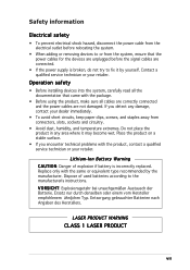
...LASER PRODUCT vii If you encounter technical problems with the package. • Before using the product, make sure all the documentation that the power cables for the devices are unplugged before relocating the system. • When adding or removing devices to or from connectors, slots, sockets and... same or equivalent type recommended by yourself. Safety information Electrical safety • To prevent electrical shock hazard, disconnect the power cable from the electrical outlet before the signal cables are connected. • If the power supply is incorrectly replaced.
...LASER PRODUCT vii If you encounter technical problems with the package. • Before using the product, make sure all the documentation that the power cables for the devices are unplugged before relocating the system. • When adding or removing devices to or from connectors, slots, sockets and... same or equivalent type recommended by yourself. Safety information Electrical safety • To prevent electrical shock hazard, disconnect the power cable from the electrical outlet before the signal cables are connected. • If the power supply is incorrectly replaced.

Vintage-PE1 User''s Manual for English E2012
Page 10
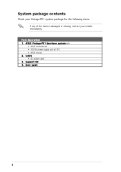
System package contents Check your Vintage-PE1 system package for the following items. If any of the items is damaged or missing, contact your retailer immediately. User guide x Cable • AC power cable 3 . Support CD 4 . Item description 1 . A S U S V i n t a g e - P E 1 b a r e b o n e s y s t e m with • ASUS motherboard • 300 W power supply unit w/ PFC • ASUS chassis 2.
System package contents Check your Vintage-PE1 system package for the following items. If any of the items is damaged or missing, contact your retailer immediately. User guide x Cable • AC power cable 3 . Support CD 4 . Item description 1 . A S U S V i n t a g e - P E 1 b a r e b o n e s y s t e m with • ASUS motherboard • 300 W power supply unit w/ PFC • ASUS chassis 2.

Vintage-PE1 User''s Manual for English E2012
Page 15
... fan that provides ventilation inside the system chassis. 1 5 . ASUS Vintage-PE1 1-5 L A N ( R J - 4 5 ) p o r t . This port allows Gigabit connection to the voltage supply in your area. This port connects IEEE 1394 devices such as digital still/video cameras, camcorders, external disk drives, or other devices. 1 6 . This connector is for the power cable and plug. 1 1 . This vent is for...
... fan that provides ventilation inside the system chassis. 1 5 . ASUS Vintage-PE1 1-5 L A N ( R J - 4 5 ) p o r t . This port allows Gigabit connection to the voltage supply in your area. This port connects IEEE 1394 devices such as digital still/video cameras, camcorders, external disk drives, or other devices. 1 6 . This connector is for the power cable and plug. 1 1 . This vent is for...
Vintage-PE1 User''s Manual for English E2012
Page 17
... reference. Hard disk drive bay 5. Expansion card slots 13. Floppy disk drive bay 3. AGP 8X slot 10. ASUS motherboard 7. DIMM sockets 8. PCI slots 11. Chassis fan 6. Serial ATA connectors 12. Front panel cover 4. Power supply unit ASUS Vintage-PE1 1-7 LGA775 socket with PnP cap 9. 1.4 Internal components The illustration below is the internal view of the system...
... reference. Hard disk drive bay 5. Expansion card slots 13. Floppy disk drive bay 3. AGP 8X slot 10. ASUS motherboard 7. DIMM sockets 8. PCI slots 11. Chassis fan 6. Serial ATA connectors 12. Front panel cover 4. Power supply unit ASUS Vintage-PE1 1-7 LGA775 socket with PnP cap 9. 1.4 Internal components The illustration below is the internal view of the system...

Vintage-PE1 User''s Manual for English E2012
Page 23
... drive. 6. 5. ASUS Vintage-PE1 2-19 Connect one end of the audio cable to the 4-pin connector at the back of the IDE ribbon cable to the IDE interface at the back of the audio cable to pin 1 Power cable 8. See page 4-9 for the location of this connector. 9. Connect a power cable from the power supply to the power connector...
... drive. 6. 5. ASUS Vintage-PE1 2-19 Connect one end of the audio cable to the 4-pin connector at the back of the IDE ribbon cable to the IDE interface at the back of the audio cable to pin 1 Power cable 8. See page 4-9 for the location of this connector. 9. Connect a power cable from the power supply to the power connector...
Vintage-PE1 User''s Manual for English E2012
Page 25
...section. 3 2 • If you will install only one hard disk drive, make sure to keep the system from the power supply unit to the power connector at the back of the PRI_IDE1 connector. 3. Follow steps 1-4 of the drive. Connect the gray interface of the drive.... SATA power adapter plug O R the legacy 4-pin power connector. Refer to the HDD documentation on the drive. 4. Connect a 15-pin Serial ATA power plug from the power supply unit to set the drive as Master device before connecting the IDE cable and power plug. ASUS Vintage-PE1 2-21 Connect a 4-pin power plug from...
...section. 3 2 • If you will install only one hard disk drive, make sure to keep the system from the power supply unit to the power connector at the back of the PRI_IDE1 connector. 3. Follow steps 1-4 of the drive. Connect the gray interface of the drive.... SATA power adapter plug O R the legacy 4-pin power connector. Refer to the HDD documentation on the drive. 4. Connect a 15-pin Serial ATA power plug from the power supply unit to set the drive as Master device before connecting the IDE cable and power plug. ASUS Vintage-PE1 2-21 Connect a 4-pin power plug from...

Vintage-PE1 User''s Manual for English E2012
Page 26
... to page 2-3 of section "2.3 Removing the side plates and front cover" 2. To install a floppy disk drive: 1. Connect a power cable from the power supply unit to the signal connector at the back of the drive. 5. Carefully insert the floppy disk drive into the floppy drive bay until... 3. Remove the front panel cover. Connect the floppy disk drive signal cable to the power connector at the back of the floppy disk drive. 6 4 2-22 Chapter 2: Basic installation 2.9 Installing a floppy disk drive The Vintage-PE1 system comes with one 3.25-inch drive bay for a floppy disk drive.
... to page 2-3 of section "2.3 Removing the side plates and front cover" 2. To install a floppy disk drive: 1. Connect a power cable from the power supply unit to the signal connector at the back of the drive. 5. Carefully insert the floppy disk drive into the floppy drive bay until... 3. Remove the front panel cover. Connect the floppy disk drive signal cable to the power connector at the back of the floppy disk drive. 6 4 2-22 Chapter 2: Basic installation 2.9 Installing a floppy disk drive The Vintage-PE1 system comes with one 3.25-inch drive bay for a floppy disk drive.

Vintage-PE1 User''s Manual for English E2012
Page 40
2. This feature requires an ATX power supply that can supply at least 1A on the keyboard. KBPWR1 12 23 +5V +5VSB (Default) ® Keyboard power setting 4-4 Chapter 4: Motherboard info Set this jumper to wake up feature. Default setting is 2-3. Keyboard power (3-pin KBPWR1) This jumper allows you to enable or disable the keyboard wake-up the computer when you do not want to pins 1-2 (+5V) if you press a key on the +5VSB lead, and a corresponding setting in the BIOS.
2. This feature requires an ATX power supply that can supply at least 1A on the keyboard. KBPWR1 12 23 +5V +5VSB (Default) ® Keyboard power setting 4-4 Chapter 4: Motherboard info Set this jumper to wake up feature. Default setting is 2-3. Keyboard power (3-pin KBPWR1) This jumper allows you to enable or disable the keyboard wake-up the computer when you do not want to pins 1-2 (+5V) if you press a key on the +5VSB lead, and a corresponding setting in the BIOS.
Vintage-PE1 User''s Manual for English E2012
Page 44
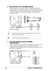
ATX power connectors (20-pin ATXPWR1, 4-pin ATX12V1) These connectors are designed to 480 Mbps connection speed. Connect the USB/GAME...+5.0VDC COM +3.3VDC +3.3VDC +5.0VDC +5.0VDC -5.0VDC COM COM COM PS_ON# COM -12.0VDC +3.3VDC 4-8 Chapter 4: Motherboard info The plugs from the power supply are for USB 2.0 ports. USB+5V USB_P8USB_P8+ GND NC USB+5V USB_P6USB_P6+ GND NC ® ® USB+5V USB_P7USB_P7+ GND USB+5V USB_P5USB_P5+..., then install the module to the USB connectors. 6 . USB connectors (10-1 pin USB56, USB78) These connectors are for ATX power supply plugs.
ATX power connectors (20-pin ATXPWR1, 4-pin ATX12V1) These connectors are designed to 480 Mbps connection speed. Connect the USB/GAME...+5.0VDC COM +3.3VDC +3.3VDC +5.0VDC +5.0VDC -5.0VDC COM COM COM PS_ON# COM -12.0VDC +3.3VDC 4-8 Chapter 4: Motherboard info The plugs from the power supply are for USB 2.0 ports. USB+5V USB_P8USB_P8+ GND NC USB+5V USB_P6USB_P6+ GND NC ® ® USB+5V USB_P7USB_P7+ GND USB+5V USB_P5USB_P5+..., then install the module to the USB connectors. 6 . USB connectors (10-1 pin USB56, USB78) These connectors are for ATX power supply plugs.

Vintage-PE1 User''s Manual for English E2012
Page 76
... to turn on the system through a PCI LAN or modem card. This feature requires an ATX power supply that provides at least 1A on the +5VSB lead. Configuration options: [On/Off] [Suspend] Restore on AC Power Loss [Always OFF] When set to Last State, the system goes into off or on state... the system to turn on the system. This feature requires an ATX power supply that provides at least 1A on the +5VSB lead. 5.5.5 APM Configuration Power Button Mode Restore on AC Power Loss Power On By PS2 Keyboard Power On By PS2 Mouse Power On by keyboard feature or use the PS/2 mouse to go into ...
... to turn on the system through a PCI LAN or modem card. This feature requires an ATX power supply that provides at least 1A on the +5VSB lead. Configuration options: [On/Off] [Suspend] Restore on AC Power Loss [Always OFF] When set to Last State, the system goes into off or on state... the system to turn on the system. This feature requires an ATX power supply that provides at least 1A on the +5VSB lead. 5.5.5 APM Configuration Power Button Mode Restore on AC Power Loss Power On By PS2 Keyboard Power On By PS2 Mouse Power On by keyboard feature or use the PS/2 mouse to go into ...