
User Manual
Page 5
...hard disk drive 2-22 2.8 Reinstalling the front panel assembly and side cover 2-23 Chapter 3: Starting up 3.1 Installing an operating system 3-2 3.2 Powering up 3-2 3.3 Support DVD information 3-2 3.3.1 Running the support DVD 3-3 3.3.2 Utilities menu 3-4 3.3.3 Manual menu 3-6 3.3.4 ASUS Contact information 3-7 3.3.5 Other information 3-8 3.4 Software information 3-10 ASUS PC Probe II 3-10 Chapter 4: Motherboard information 4.1 Introduction 4-2 4.2 Motherboard layout 4-2 4.3 Jumpers 4-3 4.3 Connectors 4-5 Chapter 5: BIOS setup 5.1 Managing and updating your BIOS 5-2 5.1.1 ASUS...
...hard disk drive 2-22 2.8 Reinstalling the front panel assembly and side cover 2-23 Chapter 3: Starting up 3.1 Installing an operating system 3-2 3.2 Powering up 3-2 3.3 Support DVD information 3-2 3.3.1 Running the support DVD 3-3 3.3.2 Utilities menu 3-4 3.3.3 Manual menu 3-6 3.3.4 ASUS Contact information 3-7 3.3.5 Other information 3-8 3.4 Software information 3-10 ASUS PC Probe II 3-10 Chapter 4: Motherboard information 4.1 Introduction 4-2 4.2 Motherboard layout 4-2 4.3 Jumpers 4-3 4.3 Connectors 4-5 Chapter 5: BIOS setup 5.1 Managing and updating your BIOS 5-2 5.1.1 ASUS...

User Manual
Page 9
... instructions on the front and rear panel, and internal components. 2. Chapter 3: Starting up the system and install drivers and utilities from the support DVD. 4. Chapter 4: Motherboard info This chapter gives information about the ASUS Vintage V4-Series P5G43 barebone system. This guide is organized This guide contains the following parts: 1. This chapter includes the motherboard layout, jumper settings, and connector locations. 5. The chapter lists the system features, including introduction on how to change system settings through the BIOS Setup...
... instructions on the front and rear panel, and internal components. 2. Chapter 3: Starting up the system and install drivers and utilities from the support DVD. 4. Chapter 4: Motherboard info This chapter gives information about the ASUS Vintage V4-Series P5G43 barebone system. This guide is organized This guide contains the following parts: 1. This chapter includes the motherboard layout, jumper settings, and connector locations. 5. The chapter lists the system features, including introduction on how to change system settings through the BIOS Setup...
User Manual
Page 11
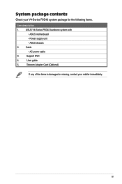
Cable • AC power cable 3. User guide 5. xi Support DVD 4. Telecom Adapter Card (Optional) If any of the items is damaged or missing, contact your V4-Series P5G43 system package for the following items. Item description 1. System package contents Check your retailer immediately. ASUS V4-Series P5G43 barebone system with • ASUS motherboatd • Power supply unit • ASUS chassis 2.
Cable • AC power cable 3. User guide 5. xi Support DVD 4. Telecom Adapter Card (Optional) If any of the items is damaged or missing, contact your V4-Series P5G43 system package for the following items. Item description 1. System package contents Check your retailer immediately. ASUS V4-Series P5G43 barebone system with • ASUS motherboatd • Power supply unit • ASUS chassis 2.
User Manual
Page 14
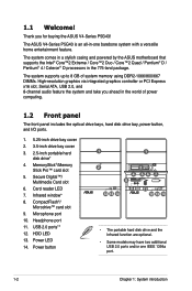
... graphics controller or PCI Express x16 slot, Serial ATA, USB 2.0, and 8-channel audio feature the system and take you for buying the ASUS V4-Series P5G43! Infrared window* 8. CompactFlash®/ Microdrive™ card slot 9. Headphone port 11. MemoryStick®/Memory Stick Pro™ card slot 5. Power button 1 1 2 12 13 14 3 4 56 7 8 9 10 11 12 13 14 • The portable hard disk drive and the Infrared function are optional. • Some models may have two additional USB 2.0 ports...
... graphics controller or PCI Express x16 slot, Serial ATA, USB 2.0, and 8-channel audio feature the system and take you for buying the ASUS V4-Series P5G43! Infrared window* 8. CompactFlash®/ Microdrive™ card slot 9. Headphone port 11. MemoryStick®/Memory Stick Pro™ card slot 5. Power button 1 1 2 12 13 14 3 4 56 7 8 9 10 11 12 13 14 • The portable hard disk drive and the Infrared function are optional. • Some models may have two additional USB 2.0 ports...

User Manual
Page 15
... port. This port is for a VGA monitor or other VGA-compatible devices. 3. These two 4-pin Universal Serial Bus (USB) ports are available for the LAN port LED indications. Supported by Gigabit LAN controller, this port allows Gigabit connection to the table below for connecting USB 2.0 devices. 4. LAN (RJ-45) port. PS/2 keyboard port (purple). USB 2.0 ports. Refer to a Local Area Network (LAN) through a network hub. 1.3 Rear panel The system rear panel includes the power connector and several I/O ports that allow convenient connection of devices. 16 1 12 14 2 DVI HDMI...
... port. This port is for a VGA monitor or other VGA-compatible devices. 3. These two 4-pin Universal Serial Bus (USB) ports are available for the LAN port LED indications. Supported by Gigabit LAN controller, this port allows Gigabit connection to the table below for connecting USB 2.0 devices. 4. LAN (RJ-45) port. PS/2 keyboard port (purple). USB 2.0 ports. Refer to a Local Area Network (LAN) through a network hub. 1.3 Rear panel The system rear panel includes the power connector and several I/O ports that allow convenient connection of devices. 16 1 12 14 2 DVI HDMI...

User Manual
Page 17
... selector switch located beside the power connector. USB 2.0 ports. These two 4-pin Universal Serial Bus (USB) ports are available for audio/video devices, storage peripherals, PCs, or portable devices. 18. Remove these covers when installing expansion cards. 16. Power supply unit fan vent. If the voltage supply in your area is 200‑240 V, set this switch to 230 V. 115V/230V Voltage selector Setting the switch to 115 V. Expansion slot covers. This 6-pin IEEE 1394a port provides high-speed connectivity for connecting USB 2.0 devices. If...
... selector switch located beside the power connector. USB 2.0 ports. These two 4-pin Universal Serial Bus (USB) ports are available for audio/video devices, storage peripherals, PCs, or portable devices. 18. Remove these covers when installing expansion cards. 16. Power supply unit fan vent. If the voltage supply in your area is 200‑240 V, set this switch to 230 V. 115V/230V Voltage selector Setting the switch to 115 V. Expansion slot covers. This 6-pin IEEE 1394a port provides high-speed connectivity for connecting USB 2.0 devices. If...
User Manual
Page 37
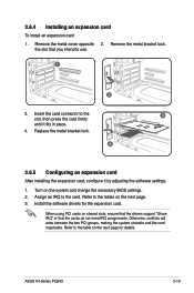
... expansion card: 1. Insert the card connector to the card. Refer to use. 1 2 3. When using PCI cards on the next page for the expansion card. the slot that the cards do not need IRQ assignments. ASUS V4-Series P5G43 2-19 Assign an IRQ to the 3 slot, then press the card firmly until it by adjusting the software settings. 1. Turn on the next page. 3. Refer to the table on shared slots, ensure that the drivers support...
... expansion card: 1. Insert the card connector to the card. Refer to use. 1 2 3. When using PCI cards on the next page for the expansion card. the slot that the cards do not need IRQ assignments. ASUS V4-Series P5G43 2-19 Assign an IRQ to the 3 slot, then press the card firmly until it by adjusting the software settings. 1. Turn on the next page. 3. Refer to the table on shared slots, ensure that the drivers support...

User Manual
Page 44
... system supports Windows® XP/Vista operating systems (OS). Because motherboard settings and hardware options vary, use the setup procedures presented in this chapter for updates. 3-2 Chapter 3: Starting up Press the system power button ( ) to enter the OS. Use the bundled floppy disk when installing Windows XP OS to a Serial ATA hard drive. • From the Windows XP setup screen, press F6 when prompted then follow succeeding screen instructions to your hardware. Refer to install the SATA drivers. 3.2 Powering up Visit the ASUS...
... system supports Windows® XP/Vista operating systems (OS). Because motherboard settings and hardware options vary, use the setup procedures presented in this chapter for updates. 3-2 Chapter 3: Starting up Press the system power button ( ) to enter the OS. Use the bundled floppy disk when installing Windows XP OS to a Serial ATA hard drive. • From the Windows XP setup screen, press F6 when prompted then follow succeeding screen instructions to your hardware. Refer to install the SATA drivers. 3.2 Powering up Visit the ASUS...

User Manual
Page 61
... RAM: 1. Removing the cap will cause system boot failure! Shut down the key during the boot process and enter BIOS setup to clear the Real Time Clock (RTC) RAM in CMOS, which include system setup information such as system passwords. ASUS V4-Series P5G43 4-3 Remove the onboard battery. 3. Plug the power cord and turn ON the computer. 6. Clear RTC RAM (CLRTC) This jumper allows you to re-enter data. Move the jumper cap from pins 1-2 (default) to overclocking. Re-install the battery...
... RAM: 1. Removing the cap will cause system boot failure! Shut down the key during the boot process and enter BIOS setup to clear the Real Time Clock (RTC) RAM in CMOS, which include system setup information such as system passwords. ASUS V4-Series P5G43 4-3 Remove the onboard battery. 3. Plug the power cord and turn ON the computer. 6. Clear RTC RAM (CLRTC) This jumper allows you to re-enter data. Move the jumper cap from pins 1-2 (default) to overclocking. Re-install the battery...

User Manual
Page 70
... power of a PSU with a higher power output is inadequate. • The ATX 12 V Specification 2.0-compliant (400W) PSU has been tested to support the motherboard power requirements with the following configuration: CPU: Intel® Pentium® Extreme 3.73GHz Memory: 512 MB DDR2 (x4) Graphics card: ASUS EAX1900XT Parallel ATA device: IDE hard disk drive Serial ATA device: SATA hard disk drive (x2) Optical drive: DVD-RW • If you use a PSU with more power-consuming devices. The power supply plugs are for ATX power supply plugs...
... power of a PSU with a higher power output is inadequate. • The ATX 12 V Specification 2.0-compliant (400W) PSU has been tested to support the motherboard power requirements with the following configuration: CPU: Intel® Pentium® Extreme 3.73GHz Memory: 512 MB DDR2 (x4) Graphics card: ASUS EAX1900XT Parallel ATA device: IDE hard disk drive Serial ATA device: SATA hard disk drive (x2) Optical drive: DVD-RW • If you use a PSU with more power-consuming devices. The power supply plugs are for ATX power supply plugs...

User Manual
Page 74
ASUS Update requires an Internet connection either through a network or an Internet Service Provider (ISP). Place the support DVD in Windows® environment.) 2. The ASUS Update utility allows you update the BIOS using this utility. 5-2 Chapter 5: BIOS setup The ASUS Update utility is copied to your BIOS The following utilities allow you to manage and update the motherboard Basic Input/Output System (BIOS) setup. 1. ASUS Update (Updates the BIOS in the optical drive. Quit all Windows® applications before you to restore the BIOS in the support DVD that comes ...
ASUS Update requires an Internet connection either through a network or an Internet Service Provider (ISP). Place the support DVD in Windows® environment.) 2. The ASUS Update utility allows you update the BIOS using this utility. 5-2 Chapter 5: BIOS setup The ASUS Update utility is copied to your BIOS The following utilities allow you to manage and update the motherboard Basic Input/Output System (BIOS) setup. 1. ASUS Update (Updates the BIOS in the optical drive. Quit all Windows® applications before you to restore the BIOS in the support DVD that comes ...
User Manual
Page 81
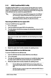
... the BIOS from the USB flash disk To recover the BIOS from the support DVD: 1. Restart the system after the utility completes the updating process. Reading file "P5QLEM.ROM". The utility will not function. otherwise, the utility will automatically checks the devices for the BIOS file. Starting BIOS recovery... Doing so can support ASUS CrashFree BIOS 3. 5.1.5 ASUS CrashFree BIOS 3 utility The ASUS CrashFree BIOS 3 is an auto recovery tool that allows you use a SATA optical drive, always connect the SATA cable to the USB port. 2. Turn...
... the BIOS from the USB flash disk To recover the BIOS from the support DVD: 1. Restart the system after the utility completes the updating process. Reading file "P5QLEM.ROM". The utility will not function. otherwise, the utility will automatically checks the devices for the BIOS file. Starting BIOS recovery... Doing so can support ASUS CrashFree BIOS 3. 5.1.5 ASUS CrashFree BIOS 3 utility The ASUS CrashFree BIOS 3 is an auto recovery tool that allows you use a SATA optical drive, always connect the SATA cable to the USB port. 2. Turn...

User Manual
Page 82
... the reset button on your screen. • Visit the ASUS website (www.asus.com) to configure your system using the provided utility described in section "5.1 Managing and updating your system using the navigation keys. • The default BIOS settings for this motherboard apply for reference purposes only, and may not exactly match what you wish to use the Setup program, you are installing a motherboard, reconfiguring your system, or prompted to make...
... the reset button on your screen. • Visit the ASUS website (www.asus.com) to configure your system using the provided utility described in section "5.1 Managing and updating your system using the navigation keys. • The default BIOS settings for this motherboard apply for reference purposes only, and may not exactly match what you wish to use the Setup program, you are installing a motherboard, reconfiguring your system, or prompted to make...

User Manual
Page 86
.... Setting to [Auto] enables the LBA mode if the device supports this mode, and if the device was not previously formatted with LBA mode disabled. Setting to [Auto] allows automatic selection of device connected to the device occurs multiple sectors at a time. Configuration options: [Not Installed] [Auto] [CDROM] [ARMD] This item does not appear when you are not user-configurable. 5.3.4 SATA 1~6 While entering Setup, the BIOS automatically detects the presence of IDE drive...
.... Setting to [Auto] enables the LBA mode if the device supports this mode, and if the device was not previously formatted with LBA mode disabled. Setting to [Auto] allows automatic selection of device connected to the device occurs multiple sectors at a time. Configuration options: [Not Installed] [Auto] [CDROM] [ARMD] This item does not appear when you are not user-configurable. 5.3.4 SATA 1~6 While entering Setup, the BIOS automatically detects the presence of IDE drive...

User Manual
Page 88
... Version : 0302 Build Date : 08/01/08 Processor Type : Intel(R) Core(TM)2 CPU 6300 @ 1.86GHz Speed : 1866MHz Count : 2 System Memory Installed Size: 512MB Usable Size: 478MB AMI BIOS Displays the auto-detected BIOS information. System Memory Displays the auto-detected system memory. 5-16 Chapter 5: BIOS setup Processor Displays the auto-detected CPU specification. This will be effective only if device is accessed throuh BIOS. Confiuration option: [Disabled] [Enabled] SATA Detect Time Out (Sec) [35] Selects...
... Version : 0302 Build Date : 08/01/08 Processor Type : Intel(R) Core(TM)2 CPU 6300 @ 1.86GHz Speed : 1866MHz Count : 2 System Memory Installed Size: 512MB Usable Size: 478MB AMI BIOS Displays the auto-detected BIOS information. System Memory Displays the auto-detected system memory. 5-16 Chapter 5: BIOS setup Processor Displays the auto-detected CPU specification. This will be effective only if device is accessed throuh BIOS. Confiuration option: [Disabled] [Enabled] SATA Detect Time Out (Sec) [35] Selects...

User Manual
Page 91
ASUS V4-Series P5G43 5-19 The values range from 0.8500V to become unstable. 5.4.2 CPU Configuration The items in this menu show the CPU-related information that the BIOS automatically detects. Configuration options: [Auto] [1.1V] [1.198V] [1.3V] [1.388V] Setting a very high voltage may damage the component permanently, and setting a very low voltage may cause the system to 1.55V with a 0.00625V interval. Advanced BIOS SETUP UTILITY Configure advanced CPU settings Module Version...
ASUS V4-Series P5G43 5-19 The values range from 0.8500V to become unstable. 5.4.2 CPU Configuration The items in this menu show the CPU-related information that the BIOS automatically detects. Configuration options: [Auto] [1.1V] [1.198V] [1.3V] [1.388V] Setting a very high voltage may damage the component permanently, and setting a very low voltage may cause the system to 1.55V with a 0.00625V interval. Advanced BIOS SETUP UTILITY Configure advanced CPU settings Module Version...

User Manual
Page 92
.... Set this item to enable or disable Inter CPU Enhanced Halt (C1E) function, a CPU power-saving function in CMOS then actual and setpoint values my differ. Configuration options: [Disabled] [Enabled] The following item appears only when you to [Enabled] for Windows XP operating system; C1E Support [Enabled] Allows you installed an Intel® Pentium® 4 or later CPU that supports the Enhanced Intel SpeedStep® Technology (EIST). 5-20 Chapter 5: BIOS setup...
.... Set this item to enable or disable Inter CPU Enhanced Halt (C1E) function, a CPU power-saving function in CMOS then actual and setpoint values my differ. Configuration options: [Disabled] [Enabled] The following item appears only when you to [Enabled] for Windows XP operating system; C1E Support [Enabled] Allows you installed an Intel® Pentium® 4 or later CPU that supports the Enhanced Intel SpeedStep® Technology (EIST). 5-20 Chapter 5: BIOS setup...

User Manual
Page 103
.... Configuration options: [Disabled] [Enabled] Full Screen Logo [Enabled] This allows you to select the power-on self tests (POST) while booting to decrease the time needed to be pressed when error occurs. Configuration options: [Disabled] [Enabled] ASUS V4-Series P5G43 5-31 Change Option F1 General Help F10 Save and Exit ESC Exit Enabling this item to [Enabled] to use the ASUS MyLogo2™ feature. Configuration options: [Force BIOS] [Keep Current] Bootup Num-Lock [On] Allows you to run Setup" during...
.... Configuration options: [Disabled] [Enabled] Full Screen Logo [Enabled] This allows you to select the power-on self tests (POST) while booting to decrease the time needed to be pressed when error occurs. Configuration options: [Disabled] [Enabled] ASUS V4-Series P5G43 5-31 Change Option F1 General Help F10 Save and Exit ESC Exit Enabling this item to [Enabled] to use the ASUS MyLogo2™ feature. Configuration options: [Force BIOS] [Keep Current] Bootup Num-Lock [On] Allows you to run Setup" during...

User Manual
Page 104
... disabled password. See section "4.3 Jumpers" for information on top of at least six letters and/or numbers, then press . 3. After you to display the configuration options. To change password. 5.6.3 Security The Security menu items allow you can clear it by erasing the CMOS Real Time Clock (RTC) RAM. Select an item then press to change the supervisor password. The message "Password Installed" appears after you successfully set or change...
... disabled password. See section "4.3 Jumpers" for information on top of at least six letters and/or numbers, then press . 3. After you to display the configuration options. To change password. 5.6.3 Security The Security menu items allow you can clear it by erasing the CMOS Real Time Clock (RTC) RAM. Select an item then press to change the supervisor password. The message "Password Installed" appears after you successfully set or change...

User Manual
Page 105
...], BIOS checks for user password when accessing the Setup utility. Select the Change User Password item and press . 2. again to any field. Change User Password Select this item to the Setup utility. Security Settings Supervisor Password : Installed User Password : Installed Change Supervisor Password User Access Level [Full Access] Change User Password Clear User Password Password Check [Setup] to change the user password, follow the same steps as Date and Time. Select Screen Select Item +- Configuration options: [Setup] [Always] ASUS V4-Series P5G43 5-33...
...], BIOS checks for user password when accessing the Setup utility. Select the Change User Password item and press . 2. again to any field. Change User Password Select this item to the Setup utility. Security Settings Supervisor Password : Installed User Password : Installed Change Supervisor Password User Access Level [Full Access] Change User Password Clear User Password Password Check [Setup] to change the user password, follow the same steps as Date and Time. Select Screen Select Item +- Configuration options: [Setup] [Always] ASUS V4-Series P5G43 5-33...


