
V2-PE3 English Edition User's Manual
Page 4
... system 3-2 3.2 Powering up 3-2 3.3 Support CD information 3-2 3.3.1 Running the support CD 3-3 3.3.2 Utilities menu 3-4 3.3.3 Make disk 3-5 3.3.4 ASUS contact information 3-5 3.4 Software information 3-6 Chapter 4: Motherboard Info 4.1 Introduction 4-2 4.2 Motherboard layout 4-2 4.3 Jumpers 4-3 4.4 Connectors 4-5 Chapter 5: BIOS setup 5.1 Managing and updating your BIOS 5-2 5.1.1 Creating a bootable floppy disk 5-2 5.1.2 ASUS EZ Flash utility 5-3 5.1.3 Award BIOS Flash Uuility 5-3 5.1.4 Saving the current BIOS file...
... system 3-2 3.2 Powering up 3-2 3.3 Support CD information 3-2 3.3.1 Running the support CD 3-3 3.3.2 Utilities menu 3-4 3.3.3 Make disk 3-5 3.3.4 ASUS contact information 3-5 3.4 Software information 3-6 Chapter 4: Motherboard Info 4.1 Introduction 4-2 4.2 Motherboard layout 4-2 4.3 Jumpers 4-3 4.4 Connectors 4-5 Chapter 5: BIOS setup 5.1 Managing and updating your BIOS 5-2 5.1.1 Creating a bootable floppy disk 5-2 5.1.2 ASUS EZ Flash utility 5-3 5.1.3 Award BIOS Flash Uuility 5-3 5.1.4 Saving the current BIOS file...
V2-PE3 English Edition User's Manual
Page 7
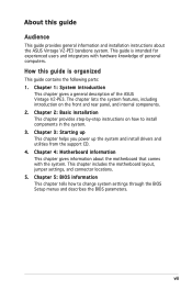
...parts: 1. How this guide Audience This guide provides general information and installation instructions about the motherboard that comes with hardware knowledge of the ASUS Vintage V2-PE3. Chapter 2: Basic installation This chapter provides step-by-step instructions on the front and ...rear panel, and internal components. 2. Chapter 4: Motherboard information This chapter gives information about the ASUS Vintage V2-PE3 barebone system. Chapter 1: System introduction This chapter gives a general description of personal computers. Chapter ...
...parts: 1. How this guide Audience This guide provides general information and installation instructions about the motherboard that comes with hardware knowledge of the ASUS Vintage V2-PE3. Chapter 2: Basic installation This chapter provides step-by-step instructions on the front and ...rear panel, and internal components. 2. Chapter 4: Motherboard information This chapter gives information about the ASUS Vintage V2-PE3 barebone system. Chapter 1: System introduction This chapter gives a general description of personal computers. Chapter ...
V2-PE3 English Edition User's Manual
Page 8
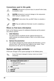
... for product and software updates. 1. User guide viii Item description 1. ASUS Vintage V2-PE3 barebone system with • ASUS motherboard • 300 W PFC power supply unit • ASUS chassis 2. NOTE: Tips and additional information to the ASUS contact information. 2. ASUS Websites The ASUS websites worldwide provide updated information on ASUS hardware and software products. Support CD 4. CAUTION: Information to prevent...
... for product and software updates. 1. User guide viii Item description 1. ASUS Vintage V2-PE3 barebone system with • ASUS motherboard • 300 W PFC power supply unit • ASUS chassis 2. NOTE: Tips and additional information to the ASUS contact information. 2. ASUS Websites The ASUS websites worldwide provide updated information on ASUS hardware and software products. Support CD 4. CAUTION: Information to prevent...
V2-PE3 English Edition User's Manual
Page 10
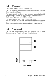
... graphics via integrated graphics controller or AGP slot, Serial ATA, USB 2.0, and 6-channel audio features the system takes you for choosing the ASUS Vintage V2-PE3! The system supports up to 2 GB of power computing. 1.2 Front panel The front panel includes the optical drive bays, floppy... at the front panel. 1 2 8 7 3 6 54 1-2 Chapter 1: System introduction The system comes in a stylish mini-tower casing and powered by the ASUS motherboard that supports the Intel® Pentium® D, Intel® Pentium® 4 or Intel® Celeron® processor in the 775-land package.
... graphics via integrated graphics controller or AGP slot, Serial ATA, USB 2.0, and 6-channel audio features the system takes you for choosing the ASUS Vintage V2-PE3! The system supports up to 2 GB of power computing. 1.2 Front panel The front panel includes the optical drive bays, floppy... at the front panel. 1 2 8 7 3 6 54 1-2 Chapter 1: System introduction The system comes in a stylish mini-tower casing and powered by the ASUS motherboard that supports the Intel® Pentium® D, Intel® Pentium® 4 or Intel® Celeron® processor in the 775-land package.
V2-PE3 English Edition User's Manual
Page 15
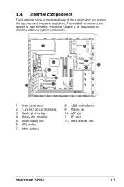
... is the internal view of the system when you remove the top cover and the power supply unit. Floppy disk drive bay 5. Metal bracket lock ASUS Vintage V2-PE3 1-7 Power supply unit 6. PCI slots 12. Chassis fan 10. CPU socket 7. DIMM sockets 8. Hard disk drive bay 4. AGP slot 11. The installed components are... Plus SATA2 SATA1 IR_CON USB78 4Mb BIOS FWP CLRTC1 F_PANEL FLOPPY 2 3 1 4 1. Proceed to Chapter 2 for your reference. Front panel cover 2. 5.25-inch optical drive bays 3. ASUS motherboard 9.
... is the internal view of the system when you remove the top cover and the power supply unit. Floppy disk drive bay 5. Metal bracket lock ASUS Vintage V2-PE3 1-7 Power supply unit 6. PCI slots 12. Chassis fan 10. CPU socket 7. DIMM sockets 8. Hard disk drive bay 4. AGP slot 11. The installed components are... Plus SATA2 SATA1 IR_CON USB78 4Mb BIOS FWP CLRTC1 F_PANEL FLOPPY 2 3 1 4 1. Proceed to Chapter 2 for your reference. Front panel cover 2. 5.25-inch optical drive bays 3. ASUS motherboard 9.
V2-PE3 English Edition User's Manual
Page 18
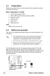
... a grounded antistatic pad or in the system. Basic components to install in the bag that came with an onboard standby power LED. Expansion card(s) 4. The motherboard comes with the component. DDR or DDR2 Dual Inline Memory Module (DIMM) 3. Hard disk drive 5. Unplug the power cable from the power outlet and make...
... a grounded antistatic pad or in the system. Basic components to install in the bag that came with an onboard standby power LED. Expansion card(s) 4. The motherboard comes with the component. DDR or DDR2 Dual Inline Memory Module (DIMM) 3. Hard disk drive 5. Unplug the power cable from the power outlet and make...

V2-PE3 English Edition User's Manual
Page 20
... released from incorrect CPU installation/removal, or misplacement/loss/incorrect removal of repair only if the damage is on the motherboard. ASUS will process Return Merchandise Authorization (RMA) requests only if the motherboard comes with the cap on your left (B) until it to the left . 2. To prevent damage to the socket pins, do...
... released from incorrect CPU installation/removal, or misplacement/loss/incorrect removal of repair only if the damage is on the motherboard. ASUS will process Return Merchandise Authorization (RMA) requests only if the motherboard comes with the cap on your left (B) until it to the left . 2. To prevent damage to the socket pins, do...
V2-PE3 English Edition User's Manual
Page 23
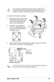
... heatsink and fan: 1. CPU_FAN GND CPU FAN PWR CPU FAN IN CPU FAN PWM ® CPU FAN Connector Do not forget to plug this connector. ASUS Vintage V2-PE3 2-7 Push down two fasteners at a time in a diagonal sequence to secure the heatsink and fan assembly in place, connect the CPU fan cable to... CPU, making sure that the Thermal Interface Material is in place. When the fan and heatsink assembly is properly applied to the connector on the motherboard. If you purchased a separate CPU heatsink and fan assembly, make sure that B the four fasteners match the holes on the...
... heatsink and fan: 1. CPU_FAN GND CPU FAN PWR CPU FAN IN CPU FAN PWM ® CPU FAN Connector Do not forget to plug this connector. ASUS Vintage V2-PE3 2-7 Push down two fasteners at a time in a diagonal sequence to secure the heatsink and fan assembly in place, connect the CPU fan cable to... CPU, making sure that the Thermal Interface Material is in place. When the fan and heatsink assembly is properly applied to the connector on the motherboard. If you purchased a separate CPU heatsink and fan assembly, make sure that B the four fasteners match the holes on the...

V2-PE3 English Edition User's Manual
Page 24
The following figure illustrates the location of the sockets: ® DDR and DDR2 DIMM Sockets To prevent damage to the motherboard, do not use DDR and DDR2 memory simultaneously. 2.5.1 Memory configurations You may detect less than 2 GB system memory when you obtain memory ...pin Double Data Rate 2 (DDR2) and two 184-pin DDR Dual Inline Memory Modules (DIMM) sockets. DDR2_A1 DDR2_B1 DDR_A1 DDR_B1 2.5 Installing a DIMM The motherboard comes with the same CAS latency. DDR2 DIMMS are notched differently to chipset resource allocation, the system may install 256 MB, 512 MB and 1 GB...
The following figure illustrates the location of the sockets: ® DDR and DDR2 DIMM Sockets To prevent damage to the motherboard, do not use DDR and DDR2 memory simultaneously. 2.5.1 Memory configurations You may detect less than 2 GB system memory when you obtain memory ...pin Double Data Rate 2 (DDR2) and two 184-pin DDR Dual Inline Memory Modules (DIMM) sockets. DDR2_A1 DDR2_B1 DDR_A1 DDR_B1 2.5 Installing a DIMM The motherboard comes with the same CAS latency. DDR2 DIMMS are notched differently to chipset resource allocation, the system may install 256 MB, 512 MB and 1 GB...
V2-PE3 English Edition User's Manual
Page 27
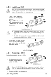
... or other system components. Failure to do not support DDR DIMMs. DO not install DDR DIMMs to both the motherboard and the components. 1. Unlock a DIMM socket by pressing the retaining clips outward. 2. ASUS Vintage V2-PE3 2-11 Firmly insert the DIMM into a socket to avoid damaging the DIMM. • The DDR2 DIMM sockets do...
... or other system components. Failure to do not support DDR DIMMs. DO not install DDR DIMMs to both the motherboard and the components. 1. Unlock a DIMM socket by pressing the retaining clips outward. 2. ASUS Vintage V2-PE3 2-11 Firmly insert the DIMM into a socket to avoid damaging the DIMM. • The DDR2 DIMM sockets do...
V2-PE3 English Edition User's Manual
Page 28
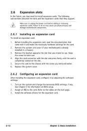
... software drivers for later use . Make sure to the tables on the slot. 5. See Chapter 5 for the card. 2. Remove the system unit cover (if your motherboard is completely seated on the next page. 3. Replace the system cover. 2.6.2 Configuring an expansion card After installing the expansion card, configure it and... for the expansion card. 2-12 Chapter 2: Basic installation The following sub-sections describe the slots and the expansion cards that you physical injury and damage motherboard components. 2.6.1 Installing an expansion card To install an expansion card: 1.
... software drivers for later use . Make sure to the tables on the slot. 5. See Chapter 5 for the card. 2. Remove the system unit cover (if your motherboard is completely seated on the next page. 3. Replace the system cover. 2.6.2 Configuring an expansion card After installing the expansion card, configure it and... for the expansion card. 2-12 Chapter 2: Basic installation The following sub-sections describe the slots and the expansion cards that you physical injury and damage motherboard components. 2.6.1 Installing an expansion card To install an expansion card: 1.
V2-PE3 English Edition User's Manual
Page 29
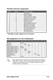
...* IRQ holder for PCI steering* PS/2 Compatible Mouse Port* Numeric Data Processor Primary IDE Channel Secondary IDE Channel * These IRQs are usually available for this motherboard A B C D E F G H PCI slot 1 shared - - - - - - - IRQ assignments for ISA or PCI devices. Onboard USB controller 2-3 shared - - - - - - - ASUS Vintage V2-PE3 2-13
...* IRQ holder for PCI steering* PS/2 Compatible Mouse Port* Numeric Data Processor Primary IDE Channel Secondary IDE Channel * These IRQs are usually available for this motherboard A B C D E F G H PCI slot 1 shared - - - - - - - IRQ assignments for ISA or PCI devices. Onboard USB controller 2-3 shared - - - - - - - ASUS Vintage V2-PE3 2-13

V2-PE3 English Edition User's Manual
Page 30
... or 0.8 V AGP cards on a AGP slot. Note the notches on the card golden fingers to be installed on this motherboard! 3.3V AGP cards are not supported in this motherboard. 2.6.4 PCI slots The PCI slots support cards such as a LAN card, SCSI card, USB card, and other cards that you buy...2.6.3 AGP slot The Accelerated Graphics Port (AGP) slot supports AGP8X/4X cards. The below figure shows a graphic card to be installed on your motherboard. When you ask for one with PCI specifications. The figure shows a LAN card to ensure that they fit the AGP slot...
... or 0.8 V AGP cards on a AGP slot. Note the notches on the card golden fingers to be installed on this motherboard! 3.3V AGP cards are not supported in this motherboard. 2.6.4 PCI slots The PCI slots support cards such as a LAN card, SCSI card, USB card, and other cards that you buy...2.6.3 AGP slot The Accelerated Graphics Port (AGP) slot supports AGP8X/4X cards. The below figure shows a graphic card to be installed on your motherboard. When you ask for one with PCI specifications. The figure shows a LAN card to ensure that they fit the AGP slot...

V2-PE3 English Edition User's Manual
Page 32
Connect the other end of the IDE ribbon cable to the secondary IDE connector (labeled SEC_IDE) on the motherboard. 8. Replace the front panel. 2-16 Chapter 2: Basic installation Remove the dummy drive slot cover from the front panel. 9. 7.
Connect the other end of the IDE ribbon cable to the secondary IDE connector (labeled SEC_IDE) on the motherboard. 8. Replace the front panel. 2-16 Chapter 2: Basic installation Remove the dummy drive slot cover from the front panel. 9. 7.

V2-PE3 English Edition User's Manual
Page 34
... power adapter plug OR the legacy 4-pin power connector. Connect a 4-pin (female) power plug from the power supply unit to a Serial ATA connector on the motherboard. 6. OR -
... power adapter plug OR the legacy 4-pin power connector. Connect a 4-pin (female) power plug from the power supply unit to a Serial ATA connector on the motherboard. 6. OR -
V2-PE3 English Edition User's Manual
Page 35
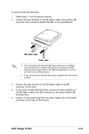
.... To install an IDE hard disk drive: 1. Follow steps 1-4 of the drive(s). Refer to the HDD documentation on how to the IDE connector on the motherboard. Connect the gray interface of the IDE ribbon cable to configure your hard disk drive as Slave. 3. Connect a 4-pin power plug from the... labeled PRI_IDE) on the drive. 4. Connect the blue interface of the IDE ribbon cable to the power connector at the back of the previous section. 2. ASUS Vintage V2-PE3 2-19
.... To install an IDE hard disk drive: 1. Follow steps 1-4 of the drive(s). Refer to the HDD documentation on how to the IDE connector on the motherboard. Connect the gray interface of the IDE ribbon cable to configure your hard disk drive as Slave. 3. Connect a 4-pin power plug from the... labeled PRI_IDE) on the drive. 4. Connect the blue interface of the IDE ribbon cable to the power connector at the back of the previous section. 2. ASUS Vintage V2-PE3 2-19
V2-PE3 English Edition User's Manual
Page 36
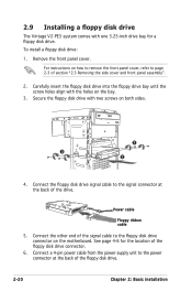
... side cover and front panel assembly". 2. 2.9 Installing a floppy disk drive The Vintage V2-PE3 system comes with one 3.25-inch drive bay for the location of the signal cable to the floppy disk drive connector on the motherboard. For instructions on how to remove the front panel cover, refer to page...
... side cover and front panel assembly". 2. 2.9 Installing a floppy disk drive The Vintage V2-PE3 system comes with one 3.25-inch drive bay for the location of the signal cable to the floppy disk drive connector on the motherboard. For instructions on how to remove the front panel cover, refer to page...
V2-PE3 English Edition User's Manual
Page 37
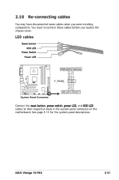
ASUS Vintage V2-PE3 2-21 You must re-connect these cables before you were installing components. See page 4-12 for the system panel descriptions. LED cables Reset button HDD LED Power Switch Power LED PWRLED PWRSW PWR_LED+ PWR_LEDPWR GND F_PANEL ® IDE_LED+ IDE_LED- 2.10 Re-connecting cables You may have disconnected some cables when you replace the chassis cover. Ground Reset System Panel Connector IDELED RESET Connect the reset button, power switch, power LED, and HDD LED cables to their respective leads in the system panel connector on the motherboard.
ASUS Vintage V2-PE3 2-21 You must re-connect these cables before you were installing components. See page 4-12 for the system panel descriptions. LED cables Reset button HDD LED Power Switch Power LED PWRLED PWRSW PWR_LED+ PWR_LEDPWR GND F_PANEL ® IDE_LED+ IDE_LED- 2.10 Re-connecting cables You may have disconnected some cables when you replace the chassis cover. Ground Reset System Panel Connector IDELED RESET Connect the reset button, power switch, power LED, and HDD LED cables to their respective leads in the system panel connector on the motherboard.
V2-PE3 English Edition User's Manual
Page 40
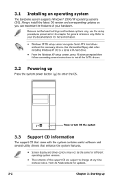
... maximize the features of your OS documentation for different operating system versions. • The contents of the support CD are subject to your hardware. Because motherboard settings and hardware options vary, use the setup procedures presented in this chapter for updates. 3-2 Chapter 3: Starting up Press the system power button ( ) to enter.... • From the Windows XP setup screen, press F6 when prompted then follow succeeding screen instructions to install the SATA drivers. 3.2 Powering up Visit the ASUS website for general reference only.
... maximize the features of your OS documentation for different operating system versions. • The contents of the support CD are subject to your hardware. Because motherboard settings and hardware options vary, use the setup procedures presented in this chapter for updates. 3-2 Chapter 3: Starting up Press the system power button ( ) to enter.... • From the Windows XP setup screen, press F6 when prompted then follow succeeding screen instructions to install the SATA drivers. 3.2 Powering up Visit the ASUS website for general reference only.
V2-PE3 English Edition User's Manual
Page 41
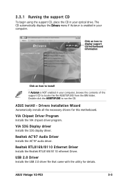
Click an icon to display support CD/motherboard information Click an item to install If Autorun is enabled in your computer. VIA Chipset Driver Program Installs the VIA chipset driver program. ASUS InstAll - Double-click the ASSETUP.EXE to run the CD. Realtek ACʼ...Installs the S3G diaplay driver. USB 2.0 Driver Installs the USB 2.0 driver file that came with the utility for this motherboard. ASUS Vintage V2-PE3 3-3 The CD automatically displays the Drivers menu if Autorun is NOT enabled in your optical drive. Drivers Installation Wizard Automatically installs all...
Click an icon to display support CD/motherboard information Click an item to install If Autorun is enabled in your computer. VIA Chipset Driver Program Installs the VIA chipset driver program. ASUS InstAll - Double-click the ASSETUP.EXE to run the CD. Realtek ACʼ...Installs the S3G diaplay driver. USB 2.0 Driver Installs the USB 2.0 driver file that came with the utility for this motherboard. ASUS Vintage V2-PE3 3-3 The CD automatically displays the Drivers menu if Autorun is NOT enabled in your optical drive. Drivers Installation Wizard Automatically installs all...


