
User Guide
Page 3
... panel 1-3 1.3 Rear panel 1-4 1.4 Internal components 1-6 Chapter 2: Basic installation 2.1 Preparation 2-2 2.2 Before you proceed 2-2 2.3 Removing the side cover and front panel assembly 2-3 2.4 Central Processing Unit (CPU 2-4 2.4.1 Overview 2-4 2.4.2 Installling the CPU 2-4 2.4.3 Installing the CPU fan and heatsink assembly ........ 2-6 2.5 Installing a DIMM 2-8 2.5.1 Memory configurations 2-8 2.5.3 Removing a DIMM 2-11 2.5.2 Installing a DIMM 2-11 2.6 Expansion slots 2-12 2.6.1 Installing an expansion card 2-12...
... panel 1-3 1.3 Rear panel 1-4 1.4 Internal components 1-6 Chapter 2: Basic installation 2.1 Preparation 2-2 2.2 Before you proceed 2-2 2.3 Removing the side cover and front panel assembly 2-3 2.4 Central Processing Unit (CPU 2-4 2.4.1 Overview 2-4 2.4.2 Installling the CPU 2-4 2.4.3 Installing the CPU fan and heatsink assembly ........ 2-6 2.5 Installing a DIMM 2-8 2.5.1 Memory configurations 2-8 2.5.3 Removing a DIMM 2-11 2.5.2 Installing a DIMM 2-11 2.6 Expansion slots 2-12 2.6.1 Installing an expansion card 2-12...

User Guide
Page 5
... 5-11 5.3.3 Legacy Diskette A 5-11 5.3.4 Primary, Secondary, Third, and Fourth IDE Master/Slave 5-12 5.3.5 System Information 5-13 5.4 Advanced menu 5-14 5.4.1 JumperFree Configuration 5-14 5.4.2 USB Configuration 5-15 5.4.3 CPU Configuration 5-16 5.4.4 Chipset 5-17 5.4.5 Onboard Devices Configuration 5-24 5.4.6 PCI PnP 5-25 5.5 Power menu 5-26 5.5.1 Suspend Mode 5-26 5.5.2 Repost Video on S3 Resume 5-26 5.5.3 ACPI 2.0 Support...
... 5-11 5.3.3 Legacy Diskette A 5-11 5.3.4 Primary, Secondary, Third, and Fourth IDE Master/Slave 5-12 5.3.5 System Information 5-13 5.4 Advanced menu 5-14 5.4.1 JumperFree Configuration 5-14 5.4.2 USB Configuration 5-15 5.4.3 CPU Configuration 5-16 5.4.4 Chipset 5-17 5.4.5 Onboard Devices Configuration 5-24 5.4.6 PCI PnP 5-25 5.5 Power menu 5-26 5.5.1 Suspend Mode 5-26 5.5.2 Repost Video on S3 Resume 5-26 5.5.3 ACPI 2.0 Support...

User Guide
Page 16
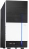
Front panel cover 2. 5.25-inch optical drive bays 3. Power supply unit 6. ASUS motherboard 9. PCI slots 13. AGP slot 11. The installed components are labeled for instructions on installing additional system components. 5 13 Super I/O PS/2KBMS T:...DDR DIMM_A1 (64 bit,184-pin module) DDR DIMM_B1 (64 bit,184-pin module) EATXPWR FLOPPY PRI_IDE SEC_IDE 2 3 1 4 1. Hard disk drive bay 4. CPU socket 7. Metal bracket lock 1-6 Chapter 1: System introduction DIMM sockets 8. Chassis fan 10. 1.4 Internal components The illustration below is the internal view of the system when...
Front panel cover 2. 5.25-inch optical drive bays 3. Power supply unit 6. ASUS motherboard 9. PCI slots 13. AGP slot 11. The installed components are labeled for instructions on installing additional system components. 5 13 Super I/O PS/2KBMS T:...DDR DIMM_A1 (64 bit,184-pin module) DDR DIMM_B1 (64 bit,184-pin module) EATXPWR FLOPPY PRI_IDE SEC_IDE 2 3 1 4 1. Hard disk drive bay 4. CPU socket 7. Metal bracket lock 1-6 Chapter 1: System introduction DIMM sockets 8. Chassis fan 10. 1.4 Internal components The illustration below is the internal view of the system when...

User Guide
Page 18
... a metal object, such as the power supply case, before installing any component, place it on a grounded antistatic pad or in the system. Central processing unit (CPU) 2. Expansion card(s) 4.
... a metal object, such as the power supply case, before installing any component, place it on a grounded antistatic pad or in the system. Central processing unit (CPU) 2. Expansion card(s) 4.

User Guide
Page 20
... The motherboard comes with gold triangle) on the CPU. Vintage2-AE1 does not support dual-core processors. 2.4.2 Installling the CPU To install a CPU: 1. Unlock the socket by pressing the lever sideways, then lift it up to 90°-100° angle, otherwise the CPU does not fit in completely. 2-4 Chapter 2: Basic installation ...Take note of these processors can run applications faster than processors with only 32-bit or 64-bit wide data paths. Locate the CPU socket on the socket to a 90°-100° angle. This mark should match a specific corner on the motherboard. ®...
... The motherboard comes with gold triangle) on the CPU. Vintage2-AE1 does not support dual-core processors. 2.4.2 Installling the CPU To install a CPU: 1. Unlock the socket by pressing the lever sideways, then lift it up to 90°-100° angle, otherwise the CPU does not fit in completely. 2-4 Chapter 2: Basic installation ...Take note of these processors can run applications faster than processors with only 32-bit or 64-bit wide data paths. Locate the CPU socket on the socket to a 90°-100° angle. This mark should match a specific corner on the motherboard. ®...

User Guide
Page 21
Carefully insert the CPU into the socket to prevent bending the pins and damaging the CPU! 5. DO NOT force the CPU into the socket until it is in place, push down the socket lever to indicate that the CPU corner with the gold triangle matches the socket corner with a small triangle. 4. 3. ASUS Vintage2-AE1 2-5 The lever clicks on the side tab to secure the CPU. When the CPU is locked. Position the CPU above the socket such that it fits in one correct orientation. The CPU fits only in place.
Carefully insert the CPU into the socket to prevent bending the pins and damaging the CPU! 5. DO NOT force the CPU into the socket until it is in place, push down the socket lever to indicate that the CPU corner with the gold triangle matches the socket corner with a small triangle. 4. 3. ASUS Vintage2-AE1 2-5 The lever clicks on the side tab to secure the CPU. When the CPU is locked. Position the CPU above the socket such that it fits in one correct orientation. The CPU fits only in place.

User Guide
Page 22
... have to remove the retention module base when installing the CPU or installing other motherboard components. • If you install the CPU fan and heatsink assembly. You do not match the CPU documentation, follow the latter. • The retention module ...properly applied to ensure optimum thermal condition and performance. • Your boxed CPU heatsink and fan assembly should come with installation instructions for the CPU, heatsink, and the retention mechanism. CPU fan CPU heatsink Retention bracket Retention bracket lock Retention module base 2-6 Chapter 2: Basic installation...
... have to remove the retention module base when installing the CPU or installing other motherboard components. • If you install the CPU fan and heatsink assembly. You do not match the CPU documentation, follow the latter. • The retention module ...properly applied to ensure optimum thermal condition and performance. • Your boxed CPU heatsink and fan assembly should come with installation instructions for the CPU, heatsink, and the retention mechanism. CPU fan CPU heatsink Retention bracket Retention bracket lock Retention module base 2-6 Chapter 2: Basic installation...

User Guide
Page 23
...lock) to the connector labeled CPU_FAN on top of the installed CPU. Connect the CPU fan cable to the retention module base until it clicks in place. 4. CPU_FAN GND +12V Rotation ® CPU fan connector ASUS Vintage2-AE1 2-7 Hardware monitoring error can not lock the retention bracket. 2.... Do not forget to plug this connector. To install the CPU fan and heatsink assembly: 1. Make sure that the fan and ...
...lock) to the connector labeled CPU_FAN on top of the installed CPU. Connect the CPU fan cable to the retention module base until it clicks in place. 4. CPU_FAN GND +12V Rotation ® CPU fan connector ASUS Vintage2-AE1 2-7 Hardware monitoring error can not lock the retention bracket. 2.... Do not forget to plug this connector. To install the CPU fan and heatsink assembly: 1. Make sure that the fan and ...

User Guide
Page 24
...) DDR DIMM pairs for each channel. • Always install DIMMs with two Double Data Rate (DDR) Dual Inline Memory Module (DIMM) sockets. Recommended memory configurations CPU Mode Single-core Dual-core Single-channel Dual-channel Single-channel Single-channel Dual-channel Sockets DIMM_A1 (black) DIMM_B1 (black) - Populated Populated 2-8 Chapter 2: Basic installation...
...) DDR DIMM pairs for each channel. • Always install DIMMs with two Double Data Rate (DDR) Dual Inline Memory Module (DIMM) sockets. Recommended memory configurations CPU Mode Single-core Dual-core Single-channel Dual-channel Single-channel Single-channel Dual-channel Sockets DIMM_A1 (black) DIMM_B1 (black) - Populated Populated 2-8 Chapter 2: Basic installation...

User Guide
Page 40
...DirectX The Microsoft® DirectX® 9.0c is for opening, viewing, and printing documents in a Windows® environment. ASUS Screen Saver Installs the ASUS screen saver. 3.3.2 Utilities menu The Utilities menu shows the applications and other software that enhances computer graphics and sounds.... ASUS PC Probe II This smart utility monitors the fan speed, CPU temperature, and system voltages, and alerts you of your computer so you keep your computer. 3-4 Chapter 3: Starting up ASUS Update The ASUS Update utility allows you to update the...
...DirectX The Microsoft® DirectX® 9.0c is for opening, viewing, and printing documents in a Windows® environment. ASUS Screen Saver Installs the ASUS screen saver. 3.3.2 Utilities menu The Utilities menu shows the applications and other software that enhances computer graphics and sounds.... ASUS PC Probe II This smart utility monitors the fan speed, CPU temperature, and system voltages, and alerts you of your computer so you keep your computer. 3-4 Chapter 3: Starting up ASUS Update The ASUS Update utility allows you to update the...

User Guide
Page 45
PC Probe II senses fan rotations, CPU temperature, and system voltages, among others. The D r i v e r s installation tab appears if your computer has an enabled Autorun feature. Follow the screen instructions... this utility, you through the installation. View the online help or readme file that came with these components. Place the support CD to complete installation. ASUS Vintage2-AE1 3-9 Click the U t i l i t i e s tab, then click A S U S P C P r o b e I I V 1 . 0 0 . 4 3. After launching the application, the PC Probe II icon appears in the Windows® taskbar. ...
PC Probe II senses fan rotations, CPU temperature, and system voltages, among others. The D r i v e r s installation tab appears if your computer has an enabled Autorun feature. Follow the screen instructions... this utility, you through the installation. View the online help or readme file that came with these components. Place the support CD to complete installation. ASUS Vintage2-AE1 3-9 Click the U t i l i t i e s tab, then click A S U S P C P r o b e I I V 1 . 0 0 . 4 3. After launching the application, the PC Probe II icon appears in the Windows® taskbar. ...

User Guide
Page 46
... turns red. Button Function Opens the C o n f i g u r a t i o n window Opens the R e p o r t window Opens the D e s k t o p M a n a g e m e n t I n t e r f a c e window Opens the P e r i p h e r a l C o m p o n e n t I n t e r c o n n e c t window Opens the W i n d o w s M a n a g e m e n t I n s t r u m e n t a t i o n window Opens the hard disk drive, memory, CPU usage window Shows/Hides the P r e f e r e n c e section Minimizes the application Closes the application Sensor alert When a system sensor detects a problem, the main window right handle turns...
... turns red. Button Function Opens the C o n f i g u r a t i o n window Opens the R e p o r t window Opens the D e s k t o p M a n a g e m e n t I n t e r f a c e window Opens the P e r i p h e r a l C o m p o n e n t I n t e r c o n n e c t window Opens the W i n d o w s M a n a g e m e n t I n s t r u m e n t a t i o n window Opens the hard disk drive, memory, CPU usage window Shows/Hides the P r e f e r e n c e section Minimizes the application Closes the application Sensor alert When a system sensor detects a problem, the main window right handle turns...

User Guide
Page 47
... list box. Click to increase value Click to detach a monitor panel from the group, click the horseshoe magnet icon. When you want to decrease value ASUS Vintage2-AE1 3-11 Click O K when finished. Adjusting the sensor threshold value You can adjust the sensor threshold value in a small monitoring panel. Hardware monitor panels ... on your computer's desktop. Large display Small display Changing the monitor panels position To change the position of a system sensor such as fan rotation, CPU temperature, and voltages. You can now move together using the C o n f i g window.
... list box. Click to increase value Click to detach a monitor panel from the group, click the horseshoe magnet icon. When you want to decrease value ASUS Vintage2-AE1 3-11 Click O K when finished. Adjusting the sensor threshold value You can adjust the sensor threshold value in a small monitoring panel. Hardware monitor panels ... on your computer's desktop. Large display Small display Changing the monitor panels position To change the position of a system sensor such as fan rotation, CPU temperature, and voltages. You can now move together using the C o n f i g window.

User Guide
Page 50
Click to display the Usage browser. If the CPU has an enabled Hyper-Threading*, two separate line graphs display the operation of the two logical processors. * O n I n t e l® C P U s o n l y . 3-14 Chapter 3: Starting up CPU usage The C P U tab displays real-time CPU usage in line graph representation. Usage The U s a g e browser displays real-time information on the CPU, hard disk drive space, and memory usage.
Click to display the Usage browser. If the CPU has an enabled Hyper-Threading*, two separate line graphs display the operation of the two logical processors. * O n I n t e l® C P U s o n l y . 3-14 Chapter 3: Starting up CPU usage The C P U tab displays real-time CPU usage in line graph representation. Usage The U s a g e browser displays real-time information on the CPU, hard disk drive space, and memory usage.

User Guide
Page 52
Enabling Cool 'n' Quiet!™ Technology To enable Cool 'n' Quiet!™ Technology: 1. Set the P o w e r O p t i o n P r o p e r t i e s depending on the CPU loading. The system motherboard supports the AMD Cool 'n' Quiet!™ Technology that dynamically and automatically change the CPU speed, voltage, and amount of power depending on the operating system. See section "5.4 Advanced Menu" for details. 4. Setting...
Enabling Cool 'n' Quiet!™ Technology To enable Cool 'n' Quiet!™ Technology: 1. Set the P o w e r O p t i o n P r o p e r t i e s depending on the CPU loading. The system motherboard supports the AMD Cool 'n' Quiet!™ Technology that dynamically and automatically change the CPU speed, voltage, and amount of power depending on the operating system. See section "5.4 Advanced Menu" for details. 4. Setting...

User Guide
Page 53
... Cool 'n' Quiet!™ software application that enables you to section "3.3.2 Utilities menu", for details. The Cool 'n' Quiet!™ application window appears and displays the current CPU frequency and core voltage. ASUS Vintage2-AE1 3-17 Refer to view your system's real-time CPU frequency and core voltage. Click the S t a r t button. 2.
... Cool 'n' Quiet!™ software application that enables you to section "3.3.2 Utilities menu", for details. The Cool 'n' Quiet!™ application window appears and displays the current CPU frequency and core voltage. ASUS Vintage2-AE1 3-17 Refer to view your system's real-time CPU frequency and core voltage. Click the S t a r t button. 2.

User Guide
Page 67
... current consumed must NOT exceed the power supply capability (+5VSB) whether under normal condition or in sleep mode. ASUS Vintage2-AE1 4-5 The USBPWR12 and USBPWR34 jumpers are for each USB port; Set to +5VSB to CPU, DRAM in slow refresh, power supply in low power mode) using the connected USB devices. 3 . The USBPWR56...) Set these jumpers to +5V to wake up from S3 and S4 sleep modes (no power to wake up the computer from S1 sleep mode (CPU stopped, DRAM refreshed, system running in reduced power mode).
... current consumed must NOT exceed the power supply capability (+5VSB) whether under normal condition or in sleep mode. ASUS Vintage2-AE1 4-5 The USBPWR12 and USBPWR34 jumpers are for each USB port; Set to +5VSB to CPU, DRAM in slow refresh, power supply in low power mode) using the connected USB devices. 3 . The USBPWR56...) Set these jumpers to +5V to wake up from S3 and S4 sleep modes (no power to wake up the computer from S1 sleep mode (CPU stopped, DRAM refreshed, system running in reduced power mode).

User Guide
Page 70
... Ground -5 Volts +5 Volts +5 Volts +5 Volts Ground +3 Volts +3 Volts Ground +5 Volts Ground +5 Volts Ground Power OK +5V Standby +12 Volts +12 Volts +3 Volts 4-8 Chapter 4: Motherboard info CPU and chassis fan connectors (3-pin CPU_FAN, CHA_FAN) The fan connectors support cooling fans of 350 mA~740 mA (8.88 W max.) or a total of the connector...
... Ground -5 Volts +5 Volts +5 Volts +5 Volts Ground +3 Volts +3 Volts Ground +5 Volts Ground +5 Volts Ground Power OK +5V Standby +12 Volts +12 Volts +3 Volts 4-8 Chapter 4: Motherboard info CPU and chassis fan connectors (3-pin CPU_FAN, CHA_FAN) The fan connectors support cooling fans of 350 mA~740 mA (8.88 W max.) or a total of the connector...

User Guide
Page 87
Processor Displays the auto-detected CPU specification. Configuration options: [Disabled] [Enabled] 5.3.5 System Information This menu gives you an overview of the general system specifications. The BIOS ..., Inc. AMI BIOS Displays the auto-detected BIOS information. Configuration options: [Auto] [Disabled] [Enabled] 32Bit Data Transfer [Enabled] Enables or disables 32-bit data transfer. ASUS Vintage2-AE1 5-13 Configuration options: [Auto] [0] [1] [2] [3] [4] DMA Mode [Auto] Selects the DMA mode. PIO Mode [Auto] Selects the PIO mode. Configuration options: [Auto] [...
Processor Displays the auto-detected CPU specification. Configuration options: [Disabled] [Enabled] 5.3.5 System Information This menu gives you an overview of the general system specifications. The BIOS ..., Inc. AMI BIOS Displays the auto-detected BIOS information. Configuration options: [Auto] [Disabled] [Enabled] 32Bit Data Transfer [Enabled] Enables or disables 32-bit data transfer. ASUS Vintage2-AE1 5-13 Configuration options: [Auto] [0] [1] [2] [3] [4] DMA Mode [Auto] Selects the DMA mode. PIO Mode [Auto] Selects the PIO mode. Configuration options: [Auto] [...

User Guide
Page 88
...Frequency (MHz) [Auto] Sets the PCI Express frequency. CPU FSB Frequency [200 MHz] Allows you to change the settings for the CPU and other system devices. JumperFree Configuration Advanced BIOS SETUP UTILITY Config System Frequency/Voltage CPU FSB Frequency AGP/PCI Frequency (MHz) PCIE Frequency (MHz)... [200 MHz] [Auto] [Auto] Adjust CPU FSB frequency. 5.4 Advanced menu The Advanced menu items allow you to adjust the CPU FSB frequency. Select Screen Select Item ...
...Frequency (MHz) [Auto] Sets the PCI Express frequency. CPU FSB Frequency [200 MHz] Allows you to change the settings for the CPU and other system devices. JumperFree Configuration Advanced BIOS SETUP UTILITY Config System Frequency/Voltage CPU FSB Frequency AGP/PCI Frequency (MHz) PCIE Frequency (MHz)... [200 MHz] [Auto] [Auto] Adjust CPU FSB frequency. 5.4 Advanced menu The Advanced menu items allow you to adjust the CPU FSB frequency. Select Screen Select Item ...

