User Guide
Page 8
... guide provides general information and installation instructions about the motherboard that comes with hardware knowledge of the barebone system. This guide is organized This guide contains the following parts: 1. Chapter 3: Starting up This chapter helps you power up the system and install drivers and utilities from the support CD. 4 . Chapter 2: Basic installation This chapter provides step-by-step instructions on the front and rear panel...
... guide provides general information and installation instructions about the motherboard that comes with hardware knowledge of the barebone system. This guide is organized This guide contains the following parts: 1. Chapter 3: Starting up This chapter helps you power up the system and install drivers and utilities from the support CD. 4 . Chapter 2: Basic installation This chapter provides step-by-step instructions on the front and rear panel...
User Guide
Page 10
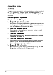
System package contents Check your Vintage2-AE1 system package for the following items. If any of the items is damaged or missing, contact your retailer immediately. 1 . Cable • AC power cable 3. User guide x A S U S V i n t a g e 2 - A E 1 b a r e b o n e s y s t e m with • ASUS motherboard • 300 W PFC power supply unit • ASUS chassis • Front panel I/O board • Wireless module (optional) 2. Support CD 4.
System package contents Check your Vintage2-AE1 system package for the following items. If any of the items is damaged or missing, contact your retailer immediately. 1 . Cable • AC power cable 3. User guide x A S U S V i n t a g e 2 - A E 1 b a r e b o n e s y s t e m with • ASUS motherboard • 300 W PFC power supply unit • ASUS chassis • Front panel I/O board • Wireless module (optional) 2. Support CD 4.

User Guide
Page 13
... Mic (pink) +port connects a microphone. 5 . Hard disk drive activity LED. 7 . M i c r o p h o n e p o r t. Press this button to reboot the system without turning off the power. These Universal Serial Bus 2.0 (USB 2.0) ports are located at the front panel. 1 2 3 6 4 5 7 8 1 . 5 . 2 5 - H e a d p h o n e p o r t. Press this button to turn the system on. 8 . 1.2 Front panel The front panel includes the optical drive bays, floppy disk drive slot, power button, and several I/O ports are...
... Mic (pink) +port connects a microphone. 5 . Hard disk drive activity LED. 7 . M i c r o p h o n e p o r t. Press this button to reboot the system without turning off the power. These Universal Serial Bus 2.0 (USB 2.0) ports are located at the front panel. 1 2 3 6 4 5 7 8 1 . 5 . 2 5 - H e a d p h o n e p o r t. Press this button to turn the system on. 8 . 1.2 Front panel The front panel includes the optical drive bays, floppy disk drive slot, power button, and several I/O ports are...

User Guide
Page 16
... optical drive bays 3. CPU socket 7. DIMM sockets 8. PCI Express x1 slot 12. Hard disk drive bay 4. Floppy disk drive bay 5. PCI slots 13. ASUS motherboard 9. 1.4 Internal components The illustration below is the internal view of the system when you remove the top cover and the power supply unit. Power supply unit 6. Metal bracket lock 1-6 Chapter 1: System introduction AGP slot 11. Chassis fan 10. The installed components are labeled for instructions on installing...
... optical drive bays 3. CPU socket 7. DIMM sockets 8. PCI Express x1 slot 12. Hard disk drive bay 4. Floppy disk drive bay 5. PCI slots 13. ASUS motherboard 9. 1.4 Internal components The illustration below is the internal view of the system when you remove the top cover and the power supply unit. Power supply unit 6. Metal bracket lock 1-6 Chapter 1: System introduction AGP slot 11. Chassis fan 10. The installed components are labeled for instructions on installing...

User Guide
Page 18
Expansion card(s) 4. Optical drive 6. Central processing unit (CPU) 2. The motherboard comes with the component. Hard disk drive 5. This LED lights up to avoid touching the ICs on them due to static ...LED 2-2 SB_PWR ON Standby Power OFF Powered Off Chapter 2: Basic installation Floppy disk drive Tool Phillips (cross) screw driver 2.2 Before you proceed Take note of the following precautions before you install components into the system. • Use a grounded wrist strap or touch a safely grounded object or a metal object, such as the power supply case, before installing...
Expansion card(s) 4. Optical drive 6. Central processing unit (CPU) 2. The motherboard comes with the component. Hard disk drive 5. This LED lights up to avoid touching the ICs on them due to static ...LED 2-2 SB_PWR ON Standby Power OFF Powered Off Chapter 2: Basic installation Floppy disk drive Tool Phillips (cross) screw driver 2.2 Before you proceed Take note of the following precautions before you install components into the system. • Use a grounded wrist strap or touch a safely grounded object or a metal object, such as the power supply case, before installing...

User Guide
Page 20
Vintage2-AE1 does not support dual-core processors. 2.4.2 Installling the CPU To install a CPU: 1. Locate the CPU socket on the socket to G o l d t r i a n g l e ensure correct installation. Unlock the socket by pressing the lever sideways, then lift it up to a 90°-100° angle. This mark should match a specific corner on the motherboard. ® CPU Socket 939 2. The 128-bit-wide data...
Vintage2-AE1 does not support dual-core processors. 2.4.2 Installling the CPU To install a CPU: 1. Locate the CPU socket on the socket to G o l d t r i a n g l e ensure correct installation. Unlock the socket by pressing the lever sideways, then lift it up to a 90°-100° angle. This mark should match a specific corner on the motherboard. ® CPU Socket 939 2. The 128-bit-wide data...

User Guide
Page 22
CPU fan CPU heatsink Retention bracket Retention bracket lock Retention module base 2-6 Chapter 2: Basic installation If the instructions in this section do not have to remove the retention module base when installing the CPU or installing other motherboard components. • If you install the CPU fan and heatsink assembly. You do not match the CPU documentation, follow the latter. • The retention module base is properly applied to...
CPU fan CPU heatsink Retention bracket Retention bracket lock Retention module base 2-6 Chapter 2: Basic installation If the instructions in this section do not have to remove the retention module base when installing the CPU or installing other motherboard components. • If you install the CPU fan and heatsink assembly. You do not match the CPU documentation, follow the latter. • The retention module base is properly applied to...

User Guide
Page 29
... expansion card. shared - - - - - - When using PCI cards on BIOS setup. 2. Turn on the system and change the necessary BIOS settings, if any. Refer to the card. shared - - -- - - - IRQ assignments for information on shared slots, ensure that the drivers support "Share IRQ" or that the cards do not need IRQ assignments; shared - - - - - shared - - - - - - - shared - - -- - - - ASUS Vintage2-AE1 2-13 2.6.2 Configuring an expansion card After installing the expansion card, configure it...
... expansion card. shared - - - - - - When using PCI cards on BIOS setup. 2. Turn on the system and change the necessary BIOS settings, if any. Refer to the card. shared - - -- - - - IRQ assignments for information on shared slots, ensure that the drivers support "Share IRQ" or that the cards do not need IRQ assignments; shared - - - - - shared - - - - - - - shared - - -- - - - ASUS Vintage2-AE1 2-13 2.6.2 Configuring an expansion card After installing the expansion card, configure it...
User Guide
Page 31
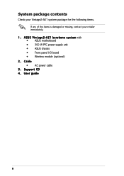
...CON1 connector on the wireless LAN module to the USB connector on the motherboard. ASUS Vintage2-AE1 2-15 Connect the omni-directional dual-band antenna to this module. 4-pin interface for information on the rear panel. 3. Secure the bracket with ... module" for the motherboard USB connector Omni-directional dual-band antenna Wireless LAN port Card bracket To install the optional wireless LAN module: 1. Follow steps 1 ~ 3 of section "2.6.1 Installing an expansion card." 2. 2.6.6 Wireless LAN module (optional) This motherboard supports an optional LAN module that allows you to set up...
...CON1 connector on the wireless LAN module to the USB connector on the motherboard. ASUS Vintage2-AE1 2-15 Connect the omni-directional dual-band antenna to this module. 4-pin interface for information on the rear panel. 3. Secure the bracket with ... module" for the motherboard USB connector Omni-directional dual-band antenna Wireless LAN port Card bracket To install the optional wireless LAN module: 1. Follow steps 1 ~ 3 of section "2.6.1 Installing an expansion card." 2. 2.6.6 Wireless LAN module (optional) This motherboard supports an optional LAN module that allows you to set up...
User Guide
Page 38
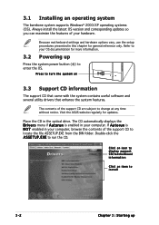
... utility drivers that enhance the system features. Place the CD in this chapter for general reference only. Refer to locate the file ASSETUP.EXE from the BIN folder. 3.1 Installing an operating system The barebone system supports Windows® 2000/XP operating systems (OS). Because motherboard settings and hardware options vary, use the setup procedures presented in the optical drive.
... utility drivers that enhance the system features. Place the CD in this chapter for general reference only. Refer to locate the file ASSETUP.EXE from the BIN folder. 3.1 Installing an operating system The barebone system supports Windows® 2000/XP operating systems (OS). Because motherboard settings and hardware options vary, use the setup procedures presented in the optical drive.

User Guide
Page 45
...configuration. By default, the main window displays the P r e f e r e n c e section. ASUS Vintage2-AE1 3-9 With this icon to view the current status of your computer is always at a healthy operating condition. Follow the screen instructions to the optical drive. You can start installation. 2. Because PC Probe II is software-based, you can close the Preference panel Main window... information Most of the applications in the support CD have wizards that will conveniently guide you of any problem with the software for more information. 3.4.1 ASUS PC Probe II PC Probe II is ...
...configuration. By default, the main window displays the P r e f e r e n c e section. ASUS Vintage2-AE1 3-9 With this icon to view the current status of your computer is always at a healthy operating condition. Follow the screen instructions to the optical drive. You can start installation. 2. Because PC Probe II is software-based, you can close the Preference panel Main window... information Most of the applications in the support CD have wizards that will conveniently guide you of any problem with the software for more information. 3.4.1 ASUS PC Probe II PC Probe II is ...
User Guide
Page 54
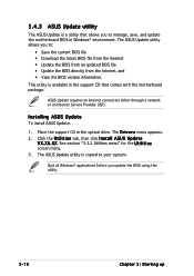
.... 3. Installing ASUS Update To install ASUS Update: 1. The ASUS Update utility is copied to : • Save the current BIOS file • Download the latest BIOS file from the Internet • Update the BIOS from an updated BIOS file • Update the BIOS directly from the Internet, and • View the BIOS version information. 3.4.3 ASUS Update utility The ASUS Update is a utility that comes with the motherboard package. This utility is available in the support...
.... 3. Installing ASUS Update To install ASUS Update: 1. The ASUS Update utility is copied to : • Save the current BIOS file • Download the latest BIOS file from the Internet • Update the BIOS from an updated BIOS file • Update the BIOS directly from the Internet, and • View the BIOS version information. 3.4.3 ASUS Update utility The ASUS Update is a utility that comes with the motherboard package. This utility is available in the support...

User Guide
Page 57
... image that the BIOS item F u l l S c r e e n L o g o is automatically installed when you customize the boot logo. The ASUS MyLogo™ is set to [Enabled] if you intend to use as your own boot logo image in GIF, JPG, or BMP file formats. Select U p d a t e B I O S, then click N e x t. 4. To launch the ASUS MyLogo™: 1. Launch the ASUS Update utility. From the left window pane, select...
... image that the BIOS item F u l l S c r e e n L o g o is automatically installed when you customize the boot logo. The ASUS MyLogo™ is set to [Enabled] if you intend to use as your own boot logo image in GIF, JPG, or BMP file formats. Select U p d a t e B I O S, then click N e x t. 4. To launch the ASUS MyLogo™: 1. Launch the ASUS Update utility. From the left window pane, select...

User Guide
Page 60
... the wireless LAN module during start-up Click R e a l t e k R T L 8 1 8 7 Wireless Ethernet Driver. 4. Place the WiFi-TV card support CD into the optical drive. 2. Click N e x t. 4. To install the wireless LAN driver: 1. The CD automatically displays the Drivers menu. 3. The R e a l t e k R T L 8 1 8 7 Wireless Network Driver a n d U t i l i t y installation window appears. Follow succeeding screen instructions to complete installation. 6. Click C a n c e l then proceed with the following instructions. Driver installation If you are using a Windows® operating system...
... the wireless LAN module during start-up Click R e a l t e k R T L 8 1 8 7 Wireless Ethernet Driver. 4. Place the WiFi-TV card support CD into the optical drive. 2. Click N e x t. 4. To install the wireless LAN driver: 1. The CD automatically displays the Drivers menu. 3. The R e a l t e k R T L 8 1 8 7 Wireless Network Driver a n d U t i l i t y installation window appears. Follow succeeding screen instructions to complete installation. 6. Click C a n c e l then proceed with the following instructions. Driver installation If you are using a Windows® operating system...

User Guide
Page 82
... enable the security password feature or change the configuration of the firmware hub. Being a menu-driven program, it lets you can change the power management settings. For example, you scroll through the various sub-menus and make it as possible. Press during the Power-On-Self-Test (POST) to run this motherboard and . 5-8 Chapter 5: BIOS setup Select the L o a d D e f a u l t S e t t i n g s item...
... enable the security password feature or change the configuration of the firmware hub. Being a menu-driven program, it lets you can change the power management settings. For example, you scroll through the various sub-menus and make it as possible. Press during the Power-On-Self-Test (POST) to run this motherboard and . 5-8 Chapter 5: BIOS setup Select the L o a d D e f a u l t S e t t i n g s item...

User Guide
Page 88
... Chapter 5: BIOS setup Main Advanced BIOS SETUP UTILITY Power Boot Exit Jumperfree Configuration USB Configuration CPU Configuration Chipset Onboard Devices Configuration PCI PnP Adjust system Frequency/Voltage,etc. 5.4 Advanced menu The Advanced menu items allow you to adjust the CPU FSB frequency. Select Screen Select Item +- Configuration options: [Auto] [66.66/33.33] [75.4/37.7] [80/40] PCIE Frequency (MHz) [Auto] Sets the PCI Express frequency. CPU FSB...
... Chapter 5: BIOS setup Main Advanced BIOS SETUP UTILITY Power Boot Exit Jumperfree Configuration USB Configuration CPU Configuration Chipset Onboard Devices Configuration PCI PnP Adjust system Frequency/Voltage,etc. 5.4 Advanced menu The Advanced menu items allow you to adjust the CPU FSB frequency. Select Screen Select Item +- Configuration options: [Auto] [66.66/33.33] [75.4/37.7] [80/40] PCIE Frequency (MHz) [Auto] Sets the PCI Express frequency. CPU FSB...
User Guide
Page 92
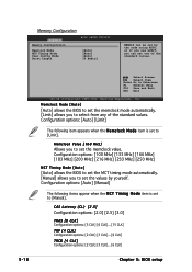
..., Inc. CAS Latency (CL) [2.5] Configuration options: [2.0] [2.5] [3.0] TRAS [8 CLK] Configuration options: [5 CLK] [6 CLK]... [15 CLK] TRP [4 CLK] Configuration options: [2 CLK] [3 CLK]... [6 CLK] TRCD [4 CLK] Configuration options: [2 CLK] [3 CLK]... [6 CLK] Chapter 5: BIOS setup Memory Configuration Advanced Memory Configuration Memclock Mode MCT Timing Mode User Config Mode Burst Length BIOS SETUP UTILITY [Auto] [Auto] [Auto] [4 Beats] MEMCLK can be set by yourself. Configuration options: [Auto] [Limit] The following...
..., Inc. CAS Latency (CL) [2.5] Configuration options: [2.0] [2.5] [3.0] TRAS [8 CLK] Configuration options: [5 CLK] [6 CLK]... [15 CLK] TRP [4 CLK] Configuration options: [2 CLK] [3 CLK]... [6 CLK] TRCD [4 CLK] Configuration options: [2 CLK] [3 CLK]... [6 CLK] Chapter 5: BIOS setup Memory Configuration Advanced Memory Configuration Memclock Mode MCT Timing Mode User Config Mode Burst Length BIOS SETUP UTILITY [Auto] [Auto] [Auto] [4 Beats] MEMCLK can be set by yourself. Configuration options: [Auto] [Limit] The following...
User Guide
Page 107
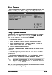
... Megatrends, Inc. To change password. The message "Password Uninstalled" appears. ASUS Vintage2-AE1 5-33 again to change the supervisor password. From the password box, type a password composed of the screen shows the default N o t I n s t a l l e d. 5.6.3 Security The Security menu items allow you set or change the system security settings. Security Settings BIOS SETUP UTILITY Boot Supervisor Password : Not Installed User Password : Not Installed Change Supervisor Password Change User Password to change other items...
... Megatrends, Inc. To change password. The message "Password Uninstalled" appears. ASUS Vintage2-AE1 5-33 again to change the supervisor password. From the password box, type a password composed of the screen shows the default N o t I n s t a l l e d. 5.6.3 Security The Security menu items allow you set or change the system security settings. Security Settings BIOS SETUP UTILITY Boot Supervisor Password : Not Installed User Password : Not Installed Change Supervisor Password Change User Password to change other items...
User Guide
Page 108
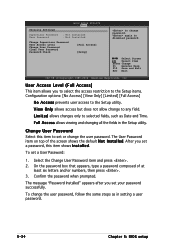
BIOS SETUP UTILITY Boot Security Settings Supervisor Password : Not Installed User Password : Not Installed Change Supervisor Password User Access Level Change User Password Clear User Password Password Check [Full Access] [Setup] to change the user password. On the password box that appears, type a password composed of the screen shows the default N o t I n s t a l l e d. User Access Level (Full Access] This item allows you set a password, this item to set or change password. Change User Password Select this item shows I n s t a l l e d. The User Password item on...
BIOS SETUP UTILITY Boot Security Settings Supervisor Password : Not Installed User Password : Not Installed Change Supervisor Password User Access Level Change User Password Clear User Password Password Check [Full Access] [Setup] to change the user password. On the password box that appears, type a password composed of the screen shows the default N o t I n s t a l l e d. User Access Level (Full Access] This item allows you set a password, this item to set or change password. Change User Password Select this item shows I n s t a l l e d. The User Password item on...

User Guide
Page 109
... RAM so it stays on even when the PC is turned off. ASUS Vintage2-AE1 5-35 Clear User Password Select this operation. F10 key can be used for the BIOS items, and save your changes before exiting. Select [ O k ...Configuration options: [Setup] [Always] 5.7 Exit menu The Exit menu items allow you selected are finished making your selections, choose this menu. Exit & Save Changes Once you are saved to [Always], BIOS checks for user password when accessing the Setup utility. Press to [Setup], BIOS checks for user password both when accessing Setup and booting the system. When set...
... RAM so it stays on even when the PC is turned off. ASUS Vintage2-AE1 5-35 Clear User Password Select this operation. F10 key can be used for the BIOS items, and save your changes before exiting. Select [ O k ...Configuration options: [Setup] [Always] 5.7 Exit menu The Exit menu items allow you selected are finished making your selections, choose this menu. Exit & Save Changes Once you are saved to [Always], BIOS checks for user password when accessing the Setup utility. Press to [Setup], BIOS checks for user password both when accessing Setup and booting the system. When set...


