
Terminator P4-533 English user''''s manual
Page 3
Features Table of contents Disclaimer/Copyrights 2 FCC/CDC statements 5 Safety information 6 About this guide 7 ASUS contact information 9 System package contents 10 Chapter 1: System Introduction 11 1.1 Front Panel Features 12 1.2 Rear Panel Features 13 1.3 Internal Features ...Basic Installation 15 2.1 Remove the cover 16 2.2 Detach the drive frame 17 2.3 Install a CPU 19 2.4 Install the CPU heatsink and fan 21 2.5 Install system memory 23 2.6 Install a hard disk drive 24 2.7 Install a CD-ROM drive 26 2.8 Install a PCI expansion card 28 2.9 Re-connect cables 29 2.9.1 Front ...
Features Table of contents Disclaimer/Copyrights 2 FCC/CDC statements 5 Safety information 6 About this guide 7 ASUS contact information 9 System package contents 10 Chapter 1: System Introduction 11 1.1 Front Panel Features 12 1.2 Rear Panel Features 13 1.3 Internal Features ...Basic Installation 15 2.1 Remove the cover 16 2.2 Detach the drive frame 17 2.3 Install a CPU 19 2.4 Install the CPU heatsink and fan 21 2.5 Install system memory 23 2.6 Install a hard disk drive 24 2.7 Install a CD-ROM drive 26 2.8 Install a PCI expansion card 28 2.9 Re-connect cables 29 2.9.1 Front ...

Terminator P4-533 English user''''s manual
Page 4
3.5 System memory 41 3.5.1 Memory configurations 41 3.6 Expansion slots 42 3.6.1 Configuring an expansion card 42 3.6.2 Standard Interrupt Assignments 42 3.6.3 IRQ assignments for this motherboard 42 3.7 Jumpers 43 3.8 Connectors 45 Chapter 4: ... 5.1 Install an operating system 90 5.2 Support CD information 90 5.2.1 Running the support CD 90 5.2.2 Installation menus 91 5.2.3 Software and drivers description 92 5.3 Software information 94 5.3.1 ASUS Update 94 5.3.2 ASUS PC Probe 96 4
3.5 System memory 41 3.5.1 Memory configurations 41 3.6 Expansion slots 42 3.6.1 Configuring an expansion card 42 3.6.2 Standard Interrupt Assignments 42 3.6.3 IRQ assignments for this motherboard 42 3.7 Jumpers 43 3.8 Connectors 45 Chapter 4: ... 5.1 Install an operating system 90 5.2 Support CD information 90 5.2.1 Running the support CD 90 5.2.2 Installation menus 91 5.2.3 Software and drivers description 92 5.3 Software information 94 5.3.1 ASUS Update 94 5.3.2 ASUS PC Probe 96 4
Terminator P4-533 English user''''s manual
Page 23
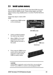
2.5 Install system memory The motherboard comes with a notch so that the notch on the DIMM matches the break on the motherboard. 2. CAUTION A DDR DIMM is properly seated. ASUS Terminator P4 533 Barebone System 23 Locate the two DIMM sockets on the socket. Unlock a socket by pressing the retaining... clips outward. 3. Align a DIMM on the socket such that it fits in place and the DIMM is keyed with two Double Data Rate (DDR) Dual Inline Memory...
2.5 Install system memory The motherboard comes with a notch so that the notch on the DIMM matches the break on the motherboard. 2. CAUTION A DDR DIMM is properly seated. ASUS Terminator P4 533 Barebone System 23 Locate the two DIMM sockets on the socket. Unlock a socket by pressing the retaining... clips outward. 3. Align a DIMM on the socket such that it fits in place and the DIMM is keyed with two Double Data Rate (DDR) Dual Inline Memory...
Terminator P4-533 English user''''s manual
Page 37
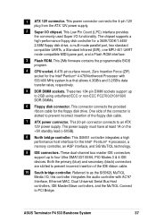
...memory controller, an AGP interface, and SiS MuTIOL technology. 9 IDE connectors. This SiS651 controller integrates a high performance host interface for the floppy disk drive. These dual-channel bus master IDE connectors support up to prevent incorrect insertion of the floppy disk cable. 7 ATX power connector. Referred to PCI Bridge. ASUS Terminator P4 533...controllers, and the MuTIOL Connect to as the SiS962L MuTIOL Media I/O, this controller integrates the audio controller with 533/400 MHz system bus that allows 4.3GB/s and 3.2GB/s data transfer rates, respectively. 5 DDR DIMM ...
...memory controller, an AGP interface, and SiS MuTIOL technology. 9 IDE connectors. This SiS651 controller integrates a high performance host interface for the floppy disk drive. These dual-channel bus master IDE connectors support up to prevent incorrect insertion of the floppy disk cable. 7 ATX power connector. Referred to PCI Bridge. ASUS Terminator P4 533...controllers, and the MuTIOL Connect to as the SiS962L MuTIOL Media I/O, this controller integrates the audio controller with 533/400 MHz system bus that allows 4.3GB/s and 3.2GB/s data transfer rates, respectively. 5 DDR DIMM ...

Terminator P4-533 English user''''s manual
Page 41
... physical dimensions as an SDR DIMM, but it has a 184-pin footprint compared to section "2.5 Install system memory" for DDR DIMMs. P4SC-E 104 Pins 80 Pins ® P4SC-E 184-Pin DDR DIMM Sockets 3.5.1 Memory configurations You may install any DDR DIMMs with 64MB, 128MB, 256MB, 512MB, and 1GB densities into the three... while an SDR DIMM is not backward compatible with SDR, and should be installed only in a socket specially designed for instructions on installing DDR DIMMs. ASUS Terminator P4 533 Barebone System 41 Therefore, a DDR DIMM is double notched.
... physical dimensions as an SDR DIMM, but it has a 184-pin footprint compared to section "2.5 Install system memory" for DDR DIMMs. P4SC-E 104 Pins 80 Pins ® P4SC-E 184-Pin DDR DIMM Sockets 3.5.1 Memory configurations You may install any DDR DIMMs with 64MB, 128MB, 256MB, 512MB, and 1GB densities into the three... while an SDR DIMM is not backward compatible with SDR, and should be installed only in a socket specially designed for instructions on installing DDR DIMMs. ASUS Terminator P4 533 Barebone System 41 Therefore, a DDR DIMM is double notched.

Terminator P4-533 English user''''s manual
Page 44
... in CMOS, that include system setup information such as system passwords, is powered by erasing the CMOS RTC RAM data. You can clear the CMOS memory of date, time, and system setup parameters by the onboard button cell battery. Hold down the key during the boot process and enter BIOS setup...
... in CMOS, that include system setup information such as system passwords, is powered by erasing the CMOS RTC RAM data. You can clear the CMOS memory of date, time, and system setup parameters by the onboard button cell battery. Hold down the key during the boot process and enter BIOS setup...

Terminator P4-533 English user''''s manual
Page 49
... USB_34 USB_56 6 10 6 10 7. Internal audio connectors (4-pin AUX1, CD1, MODEM1) These connectors allow you to receive stereo audio input from Modem) MODEM1 ASUS Terminator P4 533 Barebone System 49 It also allows the sharing of mono_in (such as a phone) and a mono_out (such as a CD-ROM, TV tuner, or MPEG card...- USB 2.0 headers (10-1 pin USB_34, USB_56) The USB_34 header is connected to support either Compact Flash card or Secure Digital (SD), Memory Stick (MS), MultiMedia Card (MMC), Smart Media cards. USBP2+ GND NC USB Power USBP3- USBP3+ GND USB Power USBP3- 6. Left ...
... USB_34 USB_56 6 10 6 10 7. Internal audio connectors (4-pin AUX1, CD1, MODEM1) These connectors allow you to receive stereo audio input from Modem) MODEM1 ASUS Terminator P4 533 Barebone System 49 It also allows the sharing of mono_in (such as a phone) and a mono_out (such as a CD-ROM, TV tuner, or MPEG card...- USB 2.0 headers (10-1 pin USB_34, USB_56) The USB_34 header is connected to support either Compact Flash card or Secure Digital (SD), Memory Stick (MS), MultiMedia Card (MMC), Smart Media cards. USBP2+ GND NC USB Power USBP3- USBP3+ GND USB Power USBP3- 6. Left ...
Terminator P4-533 English user''''s manual
Page 54
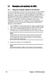
...BIOS 4.1.1 Using the computer system for the first time It is recommended that you save a copy of the original motherboard BIOS along with certain memory drivers that may be loaded when you boot from the floppy disk. Reboot the computer from the hard drive. Type FORMAT A:/S at the ...corner of the code displayed on the motherboard. This file works only in DOS mode. Type COPY D:\AFLASH\AFLASH.EXE A:\ (assuming D is a Flash Memory Writer utility that you need to create a bootable system disk. AFLASH.EXE is your screen during bootup. NOTE BIOS setup must specify "Floppy" as the...
...BIOS 4.1.1 Using the computer system for the first time It is recommended that you save a copy of the original motherboard BIOS along with certain memory drivers that may be loaded when you boot from the floppy disk. Reboot the computer from the hard drive. Type FORMAT A:/S at the ...corner of the code displayed on the motherboard. This file works only in DOS mode. Type COPY D:\AFLASH\AFLASH.EXE A:\ (assuming D is a Flash Memory Writer utility that you need to create a bootable system disk. AFLASH.EXE is your screen during bootup. NOTE BIOS setup must specify "Floppy" as the...

Terminator P4-533 English user''''s manual
Page 55
ASUS Terminator P4 533 Barebone System 55 Select 1. The Save Current BIOS To File screen appears. 6. Save Current BIOS to run AFLASH. IMPORTANT If the word "unknown" appears after Flash Memory:, the memory chip is either not programmable or is not supported by the ACPI BIOS and therefore, cannot be programmed by the Flash Memory Writer utility. 5. In DOS mode, type A:\AFLASH to File from the Main menu and press . Type a filename and the path, for example, A:\XXX-XX.XXX, then press . 4.
ASUS Terminator P4 533 Barebone System 55 Select 1. The Save Current BIOS To File screen appears. 6. Save Current BIOS to run AFLASH. IMPORTANT If the word "unknown" appears after Flash Memory:, the memory chip is either not programmable or is not supported by the ACPI BIOS and therefore, cannot be programmed by the Flash Memory Writer utility. 5. In DOS mode, type A:\AFLASH to File from the Main menu and press . Type a filename and the path, for example, A:\XXX-XX.XXX, then press . 4.

Terminator P4-533 English user''''s manual
Page 57
...only when necessary. If you saved to program the new BIOS information into the Flash ROM. If the Flash Memory Writer utility is not able to continue. ASUS Terminator P4 533 Barebone System 57 Follow the onscreen instructions to successfully update a complete BIOS file, the system may cause boot problems... load the original BIOS file you encounter problems while updating the new BIOS, DO NOT turn off the system because this happens, call the ASUS service center for support. The boot block is done, the message "Flashed Successfully" appears. 8. WARNING! The utility starts to the boot...
...only when necessary. If you saved to program the new BIOS information into the Flash ROM. If the Flash Memory Writer utility is not able to continue. ASUS Terminator P4 533 Barebone System 57 Follow the onscreen instructions to successfully update a complete BIOS file, the system may cause boot problems... load the original BIOS file you encounter problems while updating the new BIOS, DO NOT turn off the system because this happens, call the ASUS service center for support. The boot block is done, the message "Flashed Successfully" appears. 8. WARNING! The utility starts to the boot...

Terminator P4-533 English user''''s manual
Page 62
... by erasing the CMOS Real Time Clock (RTC) RAM. Forgot the password? Halt On [All Errors] This field specifies the types of conventional memory detected by the onboard button cell battery. You can access the BIOS Setup program. The same dialog box as above appears. If you did ,... information is now set passwords. Configuration options: [All Errors] [No Error] [All but Keyboard] [All but Disk] [All but Disk/Keyboard] Installed Memory [XXX MB] This field automatically displays the amount of errors that will cause the system to halt. If you did not set a Supervisor password, anyone...
... by erasing the CMOS Real Time Clock (RTC) RAM. Forgot the password? Halt On [All Errors] This field specifies the types of conventional memory detected by the onboard button cell battery. You can access the BIOS Setup program. The same dialog box as above appears. If you did ,... information is now set passwords. Configuration options: [All Errors] [No Error] [All but Keyboard] [All but Disk] [All but Disk/Keyboard] Installed Memory [XXX MB] This field automatically displays the amount of errors that will cause the system to halt. If you did not set a Supervisor password, anyone...

Terminator P4-533 English user''''s manual
Page 69
...you need to set this option to [Enabled]. If detected, the USB controller legacy mode is disabled. Configuration options: [Disabled] [Enabled] ASUS Terminator P4 533 Barebone System 69 When set to [Enabled], the BIOS loads the update on or off. Configuration options: [Disabled] [Enabled] BIOS Update ...]. If a mouse is detected at startup. When you set to the PS/2 mouse. Configuration options: [Disabled] [Enabled] [Auto] OS/2 Onboard Memory > 64M [Disabled] When using a USB device. When you set this field to [Enabled], BIOS reserves IRQ12, whether or not a PS/2 mouse...
...you need to set this option to [Enabled]. If detected, the USB controller legacy mode is disabled. Configuration options: [Disabled] [Enabled] ASUS Terminator P4 533 Barebone System 69 When set to [Enabled], the BIOS loads the update on or off. Configuration options: [Disabled] [Enabled] BIOS Update ...]. If a mouse is detected at startup. When you set to the PS/2 mouse. Configuration options: [Disabled] [Enabled] [Auto] OS/2 Onboard Memory > 64M [Disabled] When using a USB device. When you set this field to [Enabled], BIOS reserves IRQ12, whether or not a PS/2 mouse...

Terminator P4-533 English user''''s manual
Page 70
The EEPROM on the memory modules that you are using. SDRAM RAS Precharge Time [3T] This item controls the idle clocks after issuing a precharge command to [User Defined]. The default ...] [By SPD] NOTE The SDRAM parameters (items 2~5) become configurable only when you set the optimal timings for items 2-5, depending on the memory module stores critical information about the module, such as memory type, size, speed, voltage interface, and module banks. SDRAM RAS to CAS Delay [3T] This item controls the latency between...
The EEPROM on the memory modules that you are using. SDRAM RAS Precharge Time [3T] This item controls the idle clocks after issuing a precharge command to [User Defined]. The default ...] [By SPD] NOTE The SDRAM parameters (items 2~5) become configurable only when you set the optimal timings for items 2-5, depending on the memory module stores critical information about the module, such as memory type, size, speed, voltage interface, and module banks. SDRAM RAS to CAS Delay [3T] This item controls the latency between...

Terminator P4-533 English user''''s manual
Page 71
...allows you to enable or disable the AGP fast write feature. Configuration options: [Disabled] [Enabled] ASUS Terminator P4 533 Barebone System 71 Configuration options: [Disabled] [Enabled] Onboard VGA Shared Memory Size [32M] This item allows you to set this item allows 1066MB/s video data transfers through the... data transfer directly from the chipset to other system devices. Setting the address space to a particular setting makes that the more system memory you to 16MB. Configuration options: [Auto] [2T] [1T] Graphics Aperture Size [64MB] This item allows you to [4X ...
...allows you to enable or disable the AGP fast write feature. Configuration options: [Disabled] [Enabled] ASUS Terminator P4 533 Barebone System 71 Configuration options: [Disabled] [Enabled] Onboard VGA Shared Memory Size [32M] This item allows you to set this item allows 1066MB/s video data transfers through the... data transfer directly from the chipset to other system devices. Setting the address space to a particular setting makes that the more system memory you to 16MB. Configuration options: [Auto] [2T] [1T] Graphics Aperture Size [64MB] This item allows you to [4X ...

Terminator P4-533 English user''''s manual
Page 94
... icon allows you to show the screen again when you review useful information about your computer system's vital components, such as hard disk space, memory usage, and CPU type, CPU speed, and internal/external frequencies through the DMI Explorer. The PC Probe icon appears on the taskbar system tray... indicating that lets you open PC Probe or not. It also has a utility that ASUS PC Probe is a convenient utility to Programs, and then ASUS Utility, and then click Probe Vx.xx. To bypass this startup screen, clear the Show up To launch...
... icon allows you to show the screen again when you review useful information about your computer system's vital components, such as hard disk space, memory usage, and CPU type, CPU speed, and internal/external frequencies through the DMI Explorer. The PC Probe icon appears on the taskbar system tray... indicating that lets you open PC Probe or not. It also has a utility that ASUS PC Probe is a convenient utility to Programs, and then ASUS Utility, and then click Probe Vx.xx. To bypass this startup screen, clear the Show up To launch...

Terminator P4-533 English user''''s manual
Page 97
To run programs outside of devices present in your PC. Utility Lets you run a program, click Execute Program. Memory Shows the PC memory load, memory usage, and paging file usage. DMI Explorer Shows information pertinent to the PC, such as CPU type, CPU speed, and internal/external frequencies, and memory size. Device Summary Shows a summary of the ASUS Probe modules. ASUS Terminator P4 533 Barebone System 97 NOTE: This feature is currently unavailable.
To run programs outside of devices present in your PC. Utility Lets you run a program, click Execute Program. Memory Shows the PC memory load, memory usage, and paging file usage. DMI Explorer Shows information pertinent to the PC, such as CPU type, CPU speed, and internal/external frequencies, and memory size. Device Summary Shows a summary of the ASUS Probe modules. ASUS Terminator P4 533 Barebone System 97 NOTE: This feature is currently unavailable.

