

Terminator A7VT User Manual
Page 3
... you proceed 18 2.3 Removing the cover 19 2.4 Detaching the drive frame 20 2.5 Installing a CPU 22 2.6 Installing the fan and heatsink assembly 24 2.7 Installing system memory 26 2.7.1 Memory configurations 26 2.7.2 DIMM installation 27 2.8 Installing an expansion card 28 2.8.1 Expansion slots 28 2.8.2 Expansion card installation 29 2.8.3 Configuring an expansion card 29 2.8.4 Standard interrupt assignments...
... you proceed 18 2.3 Removing the cover 19 2.4 Detaching the drive frame 20 2.5 Installing a CPU 22 2.6 Installing the fan and heatsink assembly 24 2.7 Installing system memory 26 2.7.1 Memory configurations 26 2.7.2 DIMM installation 27 2.8 Installing an expansion card 28 2.8.1 Expansion slots 28 2.8.2 Expansion card installation 29 2.8.3 Configuring an expansion card 29 2.8.4 Standard interrupt assignments...

Terminator A7VT User Manual
Page 5
Table of contents 5.3.5 Installed Memory 74 5.3.6 Primary and Secondary Master/Slave 75 5.4 Advanced Menu 76 5.4.1 CPU configuration 77 5.4.2 Memory configuration 78 5.4.3 Chipset configuration 79 5.4.4 PCIPnP 81 5.4.5 Onboard device configuration 82 5.4.6 USB configuration 84 5.5 Power Menu 85 5.5.1 APM configuration 86 5.5.2 Hardware monitor 89 5.6 Boot Menu 91 5.6.1 Boot Device Priority 91 5.6.2 Removable drives 92 5.6.3 Hard Disk Drives 92 5.6.4 CD-ROM drives 93 5.6.5 Boot settings configuration 93 5.6.6 Security 95 5.7 Exit menu 96 5
Table of contents 5.3.5 Installed Memory 74 5.3.6 Primary and Secondary Master/Slave 75 5.4 Advanced Menu 76 5.4.1 CPU configuration 77 5.4.2 Memory configuration 78 5.4.3 Chipset configuration 79 5.4.4 PCIPnP 81 5.4.5 Onboard device configuration 82 5.4.6 USB configuration 84 5.5 Power Menu 85 5.5.1 APM configuration 86 5.5.2 Hardware monitor 89 5.6 Boot Menu 91 5.6.1 Boot Device Priority 91 5.6.2 Removable drives 92 5.6.3 Hard Disk Drives 92 5.6.4 CD-ROM drives 93 5.6.5 Boot settings configuration 93 5.6.6 Security 95 5.7 Exit menu 96 5
Terminator A7VT User Manual
Page 18
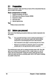
DDR Dual Inline Memory Module (DIMM) 3. Expansion card(s) 4. Central processing unit (CPU) 2. Unplug the power cable from the power outlet and make sure that you have all the components ...
DDR Dual Inline Memory Module (DIMM) 3. Expansion card(s) 4. Central processing unit (CPU) 2. Unplug the power cable from the power outlet and make sure that you have all the components ...

Terminator A7VT User Manual
Page 26
... 333/266/200 MHz • When using 100 MHz CPU FSB, any DDR DIMMs with two Double Data Rate (DDR) Dual Inline Memory Module (DIMM) sockets. 2.7 Installing system memory The motherboard comes with 64 MB, 128 MB, 256 MB, 512 MB, and 1 GB densities into the DIMM sockets. These sockets...; If you installed may install any DDR DIMM you are using unbuffered ECC or non-ECC PC2700/2100 DIMMs. 104 Pins 80 Pins A7VT ® DIMM2 DIMM1 A7VT 184-Pin DDR DIMM sockets 2.7.1 Memory configurations You may run only at a maximum of 266 MHz due to 333 MHz. 26 Chapter 2: Basic Installation
... 333/266/200 MHz • When using 100 MHz CPU FSB, any DDR DIMMs with two Double Data Rate (DDR) Dual Inline Memory Module (DIMM) sockets. 2.7 Installing system memory The motherboard comes with 64 MB, 128 MB, 256 MB, 512 MB, and 1 GB densities into the DIMM sockets. These sockets...; If you installed may install any DDR DIMM you are using unbuffered ECC or non-ECC PC2700/2100 DIMMs. 104 Pins 80 Pins A7VT ® DIMM2 DIMM1 A7VT 184-Pin DDR DIMM sockets 2.7.1 Memory configurations You may run only at a maximum of 266 MHz due to 333 MHz. 26 Chapter 2: Basic Installation
Terminator A7VT User Manual
Page 47
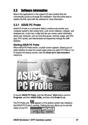
View the online help or readme file that lets you through the DMI Explorer. ASUS Terminator 1 A7VT barebone system 47 To launch ASUS PC Probe, click the Windows® Start button, point to see the status of the applications in next execution check box. It ...you review useful information about your computer system's vital components, such as hard disk space, memory usage, and CPU type, CPU speed, and internal/external frequencies through the installation. Starting ASUS PC Probe When ASUS PC Probe starts, a splash screen appears, allowing you to select whether to show the ...
View the online help or readme file that lets you through the DMI Explorer. ASUS Terminator 1 A7VT barebone system 47 To launch ASUS PC Probe, click the Windows® Start button, point to see the status of the applications in next execution check box. It ...you review useful information about your computer system's vital components, such as hard disk space, memory usage, and CPU type, CPU speed, and internal/external frequencies through the installation. Starting ASUS PC Probe When ASUS PC Probe starts, a splash screen appears, allowing you to select whether to show the ...

Terminator A7VT User Manual
Page 50
Memory Shows the PC memory load, memory usage, and paging file usage. Utility Lets you run a program, click Execute Program. This feature is currently unavailable. 50 Chapter3: Starting up To run programs outside of devices present in your PC. DMI Explorer Shows information pertinent to the PC, such as CPU type, CPU speed, and internal/external frequencies, and memory size. Device Summary Shows a summary of the ASUS Probe modules.
Memory Shows the PC memory load, memory usage, and paging file usage. Utility Lets you run a program, click Execute Program. This feature is currently unavailable. 50 Chapter3: Starting up To run programs outside of devices present in your PC. DMI Explorer Shows information pertinent to the PC, such as CPU type, CPU speed, and internal/external frequencies, and memory size. Device Summary Shows a summary of the ASUS Probe modules.
Terminator A7VT User Manual
Page 56
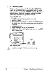
...jumper allows you to pins 1-2. Hold down the key during the boot process and enter BIOS setup to pins 2-3. 4. You can clear the CMOS memory of date, time, and system setup parameters by erasing the CMOS RTC RAM data. Keep the cap on pins 1-2 for about 5~10 seconds, then... to clear the Real Time Clock (RTC) RAM in CMOS, which include system setup information such as system passwords. Re-install the battery. 5. A7VT ® A7VT Clear RTC RAM CLRTC 12 23 Clear CMOS Normal (Default) Except when clearing the RTC RAM, never remove the cap. 56 Chapter 4: Motherboard information ...
...jumper allows you to pins 1-2. Hold down the key during the boot process and enter BIOS setup to pins 2-3. 4. You can clear the CMOS memory of date, time, and system setup parameters by erasing the CMOS RTC RAM data. Keep the cap on pins 1-2 for about 5~10 seconds, then... to clear the Real Time Clock (RTC) RAM in CMOS, which include system setup information such as system passwords. Re-install the battery. 5. A7VT ® A7VT Clear RTC RAM CLRTC 12 23 Clear CMOS Normal (Default) Except when clearing the RTC RAM, never remove the cap. 56 Chapter 4: Motherboard information ...

Terminator A7VT User Manual
Page 67
...Save only the updated BIOS file in Flash Memory Writer utility or using this utility. Rename the file to *.BIN and save it to avoid loading a wrong BIOS file. ASUS Terminator 1 A7VT barebone system 67 From your screen. 1. Click File from the ASUS website. (www.asus.com). A Format 3 1/2 Floppy Disk...reference only. Copy the original (or the latest) motherboard BIOS to update the BIOS using a bootable floppy disk with the executable Flash Memory Writer Utility (AWDFLASH.EXE). Insert the disk that contains the new BIOS file into the floppy disk drive. b. Select the 3 ...
...Save only the updated BIOS file in Flash Memory Writer utility or using this utility. Rename the file to *.BIN and save it to avoid loading a wrong BIOS file. ASUS Terminator 1 A7VT barebone system 67 From your screen. 1. Click File from the ASUS website. (www.asus.com). A Format 3 1/2 Floppy Disk...reference only. Copy the original (or the latest) motherboard BIOS to update the BIOS using a bootable floppy disk with the executable Flash Memory Writer Utility (AWDFLASH.EXE). Insert the disk that contains the new BIOS file into the floppy disk drive. b. Select the 3 ...

Terminator A7VT User Manual
Page 74
...xxxx] Sets the system to move between the month, day, and year fields. 5.3.3 Legacy Diskette A [1.44M, 3.5 in.] Sets the type of conventional memory detected by the system during the boot process. 74 Chapter 5: BIOS information Configuration options: [Disabled] [360K, 5.25 in.] [1.2M , 5.25 in... 3.5 in .] IDE Primary Master [Auto] IDE Primary Slave [Pioneer CD-ROM A] IDE Secondary Master [None] IDE Secondary Slave [None] Installed Memory [256 MB] Select Menu Item Specific Help Change the internal clock. 5.3.1 System Time [xx:xx:xx] Sets the system to 59). System Time ...
...xxxx] Sets the system to move between the month, day, and year fields. 5.3.3 Legacy Diskette A [1.44M, 3.5 in.] Sets the type of conventional memory detected by the system during the boot process. 74 Chapter 5: BIOS information Configuration options: [Disabled] [360K, 5.25 in.] [1.2M , 5.25 in... 3.5 in .] IDE Primary Master [Auto] IDE Primary Slave [Pioneer CD-ROM A] IDE Secondary Master [None] IDE Secondary Slave [None] Installed Memory [256 MB] Select Menu Item Specific Help Change the internal clock. 5.3.1 System Time [xx:xx:xx] Sets the system to 59). System Time ...

Terminator A7VT User Manual
Page 76
CPU Configuration Memory Configuration Chipset PCIPnP Onboard Device Configuration USB Configuration Select Menu Item Specific Help Press [Enter] to malfunction. Set to [Disabled] to suppress Ultra DMA capability. 5.4 ...
CPU Configuration Memory Configuration Chipset PCIPnP Onboard Device Configuration USB Configuration Select Menu Item Specific Help Press [Enter] to malfunction. Set to [Disabled] to suppress Ultra DMA capability. 5.4 ...

Terminator A7VT User Manual
Page 78
... options: [2T] [3T] tWTR [2T] Sets the tWTR time. Configuration options: [1T Command] [2T Command] Write Recovery Time [3T] Sets the DRAM write recovery time. Memory Configuration Current DRAM Frequency 133 MHz DRAM Clock [By SPD] DRAM Timing [Auto by SPD] for automatic DRAM clock detection. Configuration options: [4] [8] DRAM Command Rate...
... options: [2T] [3T] tWTR [2T] Sets the tWTR time. Configuration options: [1T Command] [2T Command] Write Recovery Time [3T] Sets the DRAM write recovery time. Memory Configuration Current DRAM Frequency 133 MHz DRAM Clock [By SPD] DRAM Timing [Auto by SPD] for automatic DRAM clock detection. Configuration options: [4] [8] DRAM Command Rate...

Terminator A7VT User Manual
Page 79
When set which graphics controller to boot from the AGP card first. Configuration options: [1X] [2X] [4X] ASUS Terminator 1 A7VT barebone system 79 Select [Onchip AGP] to use as the primary boot device. Chipset AGP Display Switch [Auto] Init Display First [PCI slot] AGP ...Configuration options: [Auto] [Onchip AGP] Init Display First [Auto] Allows you to set to [1X], the AGP interface only provides a peak data throughput of mapped memory for the following items: Graphics Aperture Size [64MB] Allows you to boot from the Onboard VGA even if there is an AGP card. Select an...
When set which graphics controller to boot from the AGP card first. Configuration options: [1X] [2X] [4X] ASUS Terminator 1 A7VT barebone system 79 Select [Onchip AGP] to use as the primary boot device. Chipset AGP Display Switch [Auto] Init Display First [PCI slot] AGP ...Configuration options: [Auto] [Onchip AGP] Init Display First [Auto] Allows you to set to [1X], the AGP interface only provides a peak data throughput of mapped memory for the following items: Graphics Aperture Size [64MB] Allows you to boot from the Onboard VGA even if there is an AGP card. Select an...

Terminator A7VT User Manual
Page 80
... chipset to set the memory space reserved for other system devices. Configuration options: [Disabled] [Enabled] Onboard Video Memory [32M] This item allows you share with VGA, the less memory space is left for the VGA frame buffer (display memory) within the system main memory. The AGP fast write... is a data transfer protocol that the more system memory you to the AGP. AGP...
... chipset to set the memory space reserved for other system devices. Configuration options: [Disabled] [Enabled] Onboard Video Memory [32M] This item allows you share with VGA, the less memory space is left for the VGA frame buffer (display memory) within the system main memory. The AGP fast write... is a data transfer protocol that the more system memory you to the AGP. AGP...

