
TX97-LE User Manual
Page 2
...altered, unless such repair, modification of alteration is defaced or missing. Copyright © 1998 ASUSTeK COMPUTER INC. IN NO EVENT SHALL ASUS, ITS DIRECTORS, OFFICERS, EMPLOYEES OR AGENTS BE LIABLE FOR ANY INDIRECT, SPECIAL, INCIDENTAL, OR CONSEQUENTIAL DAMAGES (INCLUDING DAMAGES FOR LOSS OF... or explanation and to the owners' benefit, without the express written permission of ASUSTeK COMPUTER INC. ("ASUS"). Manual revisions are both printed on the following page. Product Name: ASUS TX97-LE Manual Revision: 1.00 Release Date: January 1998 2 ASUS TX97-LE User's Manual
...altered, unless such repair, modification of alteration is defaced or missing. Copyright © 1998 ASUSTeK COMPUTER INC. IN NO EVENT SHALL ASUS, ITS DIRECTORS, OFFICERS, EMPLOYEES OR AGENTS BE LIABLE FOR ANY INDIRECT, SPECIAL, INCIDENTAL, OR CONSEQUENTIAL DAMAGES (INCLUDING DAMAGES FOR LOSS OF... or explanation and to the owners' benefit, without the express written permission of ASUSTeK COMPUTER INC. ("ASUS"). Manual revisions are both printed on the following page. Product Name: ASUS TX97-LE Manual Revision: 1.00 Release Date: January 1998 2 ASUS TX97-LE User's Manual

TX97-LE User Manual
Page 3
...tw Technical Support Fax: +886-2-2895-9254 BBS: +886-2-2896-4667 Email: tsd@asus.com.tw WWW: www.asus.com.tw Gopher: gopher.asus.com.tw FTP: ftp.asus.com.tw/pub/ASUS ASUS COMPUTER INTERNATIONAL Marketing Info Address: 721 Charcot Avenue, San Jose, CA 95131, USA Telephone...asus.com.tw WWW: www.asus.com ASUS COMPUTER GmbH Marketing Info Address: Harkort Str. 25, 40880 Ratingen, BRD, Germany Telephone: 49-2102-445011 Fax: 49-2102-442066 Email: info-ger@asus.com.tw Technical Support BBS: 49-2102-448690 Email: tsd-ger@asus.com.tw Hotline: 49-2102-499712 ASUS TX97-LE...
...tw Technical Support Fax: +886-2-2895-9254 BBS: +886-2-2896-4667 Email: tsd@asus.com.tw WWW: www.asus.com.tw Gopher: gopher.asus.com.tw FTP: ftp.asus.com.tw/pub/ASUS ASUS COMPUTER INTERNATIONAL Marketing Info Address: 721 Charcot Avenue, San Jose, CA 95131, USA Telephone...asus.com.tw WWW: www.asus.com ASUS COMPUTER GmbH Marketing Info Address: Harkort Str. 25, 40880 Ratingen, BRD, Germany Telephone: 49-2102-445011 Fax: 49-2102-442066 Email: info-ger@asus.com.tw Technical Support BBS: 49-2102-448690 Email: tsd-ger@asus.com.tw Hotline: 49-2102-499712 ASUS TX97-LE...

TX97-LE User Manual
Page 4
...CMOS Setup 38 BIOS Features Setup 41 Details of BIOS Features Setup 41 Chipset Features Setup 43 Details of the ASUS TX97-LE Motherboard 11 III. Central Processing Unit (CPU 22 4. External Connectors 25 Power Connection Procedures 33 IV. BIOS ...& Updating your Motherboard's BIOS 36 6. INSTALLATION 12 ASUS TX97-LE Motherboard Layout 12 Installation Steps 14 1. FEATURES 8 Features of the ASUS TX97-LE Motherboard 8 Introduction to ASUS Smart Series of motherboards 9 Parts of Chipset Features Setup 43 4 ASUS TX97-LE User's Manual System Memory (SIMM & DIMM 19 SIMM...
...CMOS Setup 38 BIOS Features Setup 41 Details of BIOS Features Setup 41 Chipset Features Setup 43 Details of the ASUS TX97-LE Motherboard 11 III. Central Processing Unit (CPU 22 4. External Connectors 25 Power Connection Procedures 33 IV. BIOS ...& Updating your Motherboard's BIOS 36 6. INSTALLATION 12 ASUS TX97-LE Motherboard Layout 12 Installation Steps 14 1. FEATURES 8 Features of the ASUS TX97-LE Motherboard 8 Introduction to ASUS Smart Series of motherboards 9 Parts of Chipset Features Setup 43 4 ASUS TX97-LE User's Manual System Memory (SIMM & DIMM 19 SIMM...

TX97-LE User Manual
Page 5
...-L101 Fast Ethernet Card 63 Features 64 Software Driver Support 64 Question and Answer 64 ASUS TX97-LE User's Manual 5 CONTENTS Power Management Setup 46 Details of Power Management Setup 46 PNP and PCI Setup 48 Details of PNP and PCI Setup 49 ... IDE HDD Auto Detection 52 Save & Exit Setup 53 Exit Without Saving 53 ASUS Smart Motherboard Support CD 3.10 55 Desktop Management Interface (DMI 56 Introducing the ASUS DMI Configuration Utility 56 System Requirements 56 Using the ASUS DMI Configuration Utility 57 VI. ASUS PCI SCSI Cards 59 Symbios SCSI BIOS and Drivers 59...
...-L101 Fast Ethernet Card 63 Features 64 Software Driver Support 64 Question and Answer 64 ASUS TX97-LE User's Manual 5 CONTENTS Power Management Setup 46 Details of Power Management Setup 46 PNP and PCI Setup 48 Details of PNP and PCI Setup 49 ... IDE HDD Auto Detection 52 Save & Exit Setup 53 Exit Without Saving 53 ASUS Smart Motherboard Support CD 3.10 55 Desktop Management Interface (DMI 56 Introducing the ASUS DMI Configuration Utility 56 System Requirements 56 Using the ASUS DMI Configuration Utility 57 VI. ASUS PCI SCSI Cards 59 Symbios SCSI BIOS and Drivers 59...

TX97-LE User Manual
Page 6
... any interference received, including interference that interference will not occur in accordance with the limits for a Class B digital device, pursuant to Part 15 of Communications. 6 ASUS TX97-LE User's Manual FCC & DOC COMPLIANCE Federal Communications Commission Statement This device complies with FCC regulations. However, there is required to provide reasonable protection against harmful...
... any interference received, including interference that interference will not occur in accordance with the limits for a Class B digital device, pursuant to Part 15 of Communications. 6 ASUS TX97-LE User's Manual FCC & DOC COMPLIANCE Federal Communications Commission Statement This device complies with FCC regulations. However, there is required to provide reasonable protection against harmful...

TX97-LE User Manual
Page 7
... sections: I. Introduction: Manual information and checklist II. BIOS Software: Instructions on -LAN 10/100 Ethernet Card (optional) ASUS TX97-LE User's Manual 7 Features: Information and specifications concerning this manual is organized This manual is complete. INTRODUCTION How this product... III. Installation: Instructions on the included support software VI. ASUS L101 Card: Installation of the ASUS LAN card (optional) Item Checklist Please check that your retailer. (1) ASUS Motherboard (1) 9pin male serial + 25pin male serial external connector set (1)...
... sections: I. Introduction: Manual information and checklist II. BIOS Software: Instructions on -LAN 10/100 Ethernet Card (optional) ASUS TX97-LE User's Manual 7 Features: Information and specifications concerning this manual is organized This manual is complete. INTRODUCTION How this product... III. Installation: Instructions on the included support software VI. ASUS L101 Card: Installation of the ASUS LAN card (optional) Item Checklist Please check that your retailer. (1) ASUS Motherboard (1) 9pin male serial + 25pin male serial external connector set (1)...

TX97-LE User Manual
Page 8
...four IDE devices in a small package. Is also equipped with EPP and ECP capabilities. Supports two drives of the ASUS TX97-LE Motherboard The ASUS TX97-LE is available for a standard individual infrared cable set to mount the connectors to 256MB. Supports Japanese "Floppy 3 mode"...second IrDA connector is carefully designed for wireless connections. • Desktop Management Interface (DMI): Supports DMI through optional ASUS PCIL101 Fast Ethernet card. 8 ASUS TX97-LE User's Manual FEATURES (Features) II. SIMMs and DIMMs cannot be directed from COM2 to the Infrared Module for ...
...four IDE devices in a small package. Is also equipped with EPP and ECP capabilities. Supports two drives of the ASUS TX97-LE Motherboard The ASUS TX97-LE is available for a standard individual infrared cable set to mount the connectors to 256MB. Supports Japanese "Floppy 3 mode"...second IrDA connector is carefully designed for wireless connections. • Desktop Management Interface (DMI): Supports DMI through optional ASUS PCIL101 Fast Ethernet card. 8 ASUS TX97-LE User's Manual FEATURES (Features) II. SIMMs and DIMMs cannot be directed from COM2 to the Infrared Module for ...

TX97-LE User Manual
Page 9
...the following high-level goals: Support for Plug and Play compatibility and power management for configuring and managing all the energy saving standards. ASUS TX97-LE User's Manual 9 With these features implemented in the next release of Windows 95 must be ready around the clock everyday, yet ...system damage, there is operating at a safe heat level to upgrade current hard drives or cables. • Concurrent PCI - ASUS TX97 series of all ASUS 430TX series of motherboards with Intel 430TX PCIset improves IDE transfer rate using Bus Master UltraDMA/33 IDE which increases the data ...
...the following high-level goals: Support for Plug and Play compatibility and power management for configuring and managing all the energy saving standards. ASUS TX97-LE User's Manual 9 With these features implemented in the next release of Windows 95 must be ready around the clock everyday, yet ...system damage, there is operating at a safe heat level to upgrade current hard drives or cables. • Concurrent PCI - ASUS TX97 series of all ASUS 430TX series of motherboards with Intel 430TX PCIset improves IDE transfer rate using Bus Master UltraDMA/33 IDE which increases the data ...
TX97-LE User Manual
Page 10
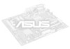
FEATURES (TX97 Series) II. This will prevent CPU damage from anywhere in one is Sleep mode and the other is the Soft-Off mode. Chassis LEDs now ... Power Button (requires ATX power supply) - When the power button is a important feature to prevent possible application crashes. This allows a computer to the user. 10 ASUS TX97-LE User's Manual FEATURES • Voltage Monitoring and Alert - The system resource monitor will warn the user before the system resources are malfunctioning, the system will...
FEATURES (TX97 Series) II. This will prevent CPU damage from anywhere in one is Sleep mode and the other is the Soft-Off mode. Chassis LEDs now ... Power Button (requires ATX power supply) - When the power button is a important feature to prevent possible application crashes. This allows a computer to the user. 10 ASUS TX97-LE User's Manual FEATURES • Voltage Monitoring and Alert - The system resource monitor will warn the user before the system resources are malfunctioning, the system will...
TX97-LE User Manual
Page 11
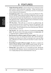
FEATURES (Motherboard Parts) II. FEATURES Parts of the ASUS TX97-LE Motherboard Super Multi-I/O 3 ISA Slots 4 PCI Slots IDE Connectors AT Power Connector ATX Power Programmable Flash ROM PS/2 Mouse, USB, IrDA Serial, Parallel, Floppy 4 SIMM Sockets 2 DIMM Sockets Intel's 430TX PCIset Thermal Sensors Hardware Monitor CPU ZIF Socket 7 "Cool" Switching Voltage Regulators 512KB Pipelined Burst L2 Cache ASUS TX97-LE User's Manual 11 II.
FEATURES (Motherboard Parts) II. FEATURES Parts of the ASUS TX97-LE Motherboard Super Multi-I/O 3 ISA Slots 4 PCI Slots IDE Connectors AT Power Connector ATX Power Programmable Flash ROM PS/2 Mouse, USB, IrDA Serial, Parallel, Floppy 4 SIMM Sockets 2 DIMM Sockets Intel's 430TX PCIset Thermal Sensors Hardware Monitor CPU ZIF Socket 7 "Cool" Switching Voltage Regulators 512KB Pipelined Burst L2 Cache ASUS TX97-LE User's Manual 11 II.
TX97-LE User Manual
Page 12
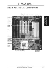
... Socket 7 CPU Voltage Switching Voltage Regulators Freq. Ratio Temp Sensor BF2 BF1 BF0 VID2 VID1 VID0 ASUS ASIC Chasis Open Alarm Infrared IDE LED Monitor LM78 Panel Connectors Chassis Fan 12 ASUS TX97-LE User's Manual III. INSTALLATION ASUS TX97-LE Motherboard Layout COM 1 Serial Ports Keyboard COM 2 Keyboard Power Floppy Drives Parallel (Printer) Port DIMM Socket...
... Socket 7 CPU Voltage Switching Voltage Regulators Freq. Ratio Temp Sensor BF2 BF1 BF0 VID2 VID1 VID0 ASUS ASIC Chasis Open Alarm Infrared IDE LED Monitor LM78 Panel Connectors Chassis Fan 12 ASUS TX97-LE User's Manual III. INSTALLATION ASUS TX97-LE Motherboard Layout COM 1 Serial Ports Keyboard COM 2 Keyboard Power Floppy Drives Parallel (Printer) Port DIMM Socket...

TX97-LE User Manual
Page 13
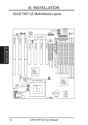
INSTALLATION (Map of Board) III. III. ASUS TX97-LE User's Manual 13 INSTALLATION Jumpers 1) BBLKW 2) CLRTC 3) KBPWR 4) FS0, FS1, FS2 5) BF0, BF1, BF2 6) VID0, VID1, VID2 p. 15 Flash ROM Boot Block Program (Disable/Enable) p. ...
INSTALLATION (Map of Board) III. III. ASUS TX97-LE User's Manual 13 INSTALLATION Jumpers 1) BBLKW 2) CLRTC 3) KBPWR 4) FS0, FS1, FS2 5) BF0, BF1, BF2 6) VID0, VID1, VID2 p. 15 Flash ROM Boot Block Program (Disable/Enable) p. ...

TX97-LE User Manual
Page 14
... graphically such as [----], [1-2], [2-3] for Open (Off). Settings with two jumper numbers require that came with two pins will be sharing pins from the system. 14 ASUS TX97-LE User's Manual To protect them against damage from yourself. The jumper settings will also be described numerically, such as to connect pins 1&2 and to touch...
... graphically such as [----], [1-2], [2-3] for Open (Off). Settings with two jumper numbers require that came with two pins will be sharing pins from the system. 14 ASUS TX97-LE User's Manual To protect them against damage from yourself. The jumper settings will also be described numerically, such as to connect pins 1&2 and to touch...

TX97-LE User Manual
Page 15
.... INSTALLATION (Jumpers) Boot Block Programming 2. RTC RAM CLRTC Clear Data [short solder points momentarily] R RTC RAM (Clear Data) CLRTC Short solder points to Clear Data ASUS TX97-LE User's Manual 15 INSTALLATION Jumper Settings 1. Real Time Clock (RTC) RAM (CLRTC) The CMOS RAM is required only if prompted by the onboard button cell...
.... INSTALLATION (Jumpers) Boot Block Programming 2. RTC RAM CLRTC Clear Data [short solder points momentarily] R RTC RAM (Clear Data) CLRTC Short solder points to Clear Data ASUS TX97-LE User's Manual 15 INSTALLATION Jumper Settings 1. Real Time Clock (RTC) RAM (CLRTC) The CMOS RAM is required only if prompted by the onboard button cell...

TX97-LE User Manual
Page 16
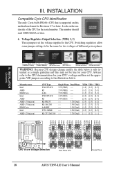
... the selection of the CPU and the External frequency (called the BUS Clock) within the CPU. CPU to power up your CPU when possible. 16 ASUS TX97-LE User's Manual The following table is set to the CPU.
... the selection of the CPU and the External frequency (called the BUS Clock) within the CPU. CPU to power up your CPU when possible. 16 ASUS TX97-LE User's Manual The following table is set to the CPU.

TX97-LE User Manual
Page 17
FS0 FS1 FS2 66MHz [2-3] [1-2] [2-3] 60MHz [1-2] [2-3] [2-3] 66MHz [2-3] [1-2] [2-3] 60MHz [1-2] [2-3] [2-3] 66MHz [2-3] [1-2] [2-3] 60MHz [1-2] [2-3] [2-3] 50MHz [2-3] [2-3] [2-3] (Freq. INSTALLATION (Jumpers) III. ASUS TX97-LE User's Manual 17 Ratio) BF0 BF1 BF2 [2-3] [2-3] [----] [2-3] [2-3] [----] [2-3] [1-2] [----] [2-3] [1-2] [----] [1-2] [1-2] [----] [1-2] [1-2] [----] [1-2] [1-2] [----] AMD-K5-PR133 AMD-K5-PR120 AMD-K5-PR100 AMD-K5-PR90 AMD-K5-PR75 100MHz 90MHz 100MHz ...
FS0 FS1 FS2 66MHz [2-3] [1-2] [2-3] 60MHz [1-2] [2-3] [2-3] 66MHz [2-3] [1-2] [2-3] 60MHz [1-2] [2-3] [2-3] 66MHz [2-3] [1-2] [2-3] 60MHz [1-2] [2-3] [2-3] 50MHz [2-3] [2-3] [2-3] (Freq. INSTALLATION (Jumpers) III. ASUS TX97-LE User's Manual 17 Ratio) BF0 BF1 BF2 [2-3] [2-3] [----] [2-3] [2-3] [----] [2-3] [1-2] [----] [2-3] [1-2] [----] [1-2] [1-2] [----] [1-2] [1-2] [----] [1-2] [1-2] [----] AMD-K5-PR133 AMD-K5-PR120 AMD-K5-PR100 AMD-K5-PR90 AMD-K5-PR75 100MHz 90MHz 100MHz ...
TX97-LE User Manual
Page 18
... 2.3Volts 2.4Volts 1 1 1 1 1 2 2 2 2 2 3 3 3 3 3 2.5Volts 2.6Volts 2.7Volts 2.8Volts 2.9Volts 1 1 1 1 2 2 2 2 3 3 3 3 CPU Vcore Voltage Selection 3.0Volts 3.1Volts 3.2Volts Dual Plane CPU 3.3Volts 1 2 3 3.4V (STD) 1 2 3 3.5V (VRE) Single Plane 18 ASUS TX97-LE User's Manual The number should read G8DC6620A or later. 6. INSTALLATION (Jumpers) Pentium MMX (P55C) Intel Pentium (P54C) AMD-K6 AMD-K5 (150MHz-233MHz) (75MHz-200MHz...
... 2.3Volts 2.4Volts 1 1 1 1 1 2 2 2 2 2 3 3 3 3 3 2.5Volts 2.6Volts 2.7Volts 2.8Volts 2.9Volts 1 1 1 1 2 2 2 2 3 3 3 3 CPU Vcore Voltage Selection 3.0Volts 3.1Volts 3.2Volts Dual Plane CPU 3.3Volts 1 2 3 3.4V (STD) 1 2 3 3.5V (VRE) Single Plane 18 ASUS TX97-LE User's Manual The number should read G8DC6620A or later. 6. INSTALLATION (Jumpers) Pentium MMX (P55C) Intel Pentium (P54C) AMD-K6 AMD-K5 (150MHz-233MHz) (75MHz-200MHz...
TX97-LE User Manual
Page 19
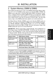
... module takes up half a row on the motherboard. Dual Inline Memory Modules (DIMMs) can be empty) Total System Memory (Max 256MB) Total Memory x1 x1 = ASUS TX97-LE User's Manual 19 If both SIMMs and DIMMs at the same time or else you will be installed in BIOS Chipset Setup of 4, 8, 16, 32...
... module takes up half a row on the motherboard. Dual Inline Memory Modules (DIMMs) can be empty) Total System Memory (Max 256MB) Total Memory x1 x1 = ASUS TX97-LE User's Manual 19 If both SIMMs and DIMMs at the same time or else you will be installed in BIOS Chipset Setup of 4, 8, 16, 32...

TX97-LE User Manual
Page 20
... one orientation as shown because the plastic safety tab on one end of the SIMM sockets requires the notched end of the support clips. 20 ASUS TX97-LE User's Manual
... one orientation as shown because the plastic safety tab on one end of the SIMM sockets requires the notched end of the support clips. 20 ASUS TX97-LE User's Manual
TX97-LE User Manual
Page 21
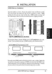
.... R 20 Pins 60 Pins 88 Pins Lock 168 Pin DIMM Memory Sockets The Dual Inline Memory Module (DIMM) must ask your retailer for this motherboard. ASUS TX97-LE User's Manual 21
.... R 20 Pins 60 Pins 88 Pins Lock 168 Pin DIMM Memory Sockets The Dual Inline Memory Module (DIMM) must ask your retailer for this motherboard. ASUS TX97-LE User's Manual 21


