
TUV4X User Manual
Page 2
...SUBJECT TO CHANGE AT ANY TIME WITHOUT NOTICE, AND SHOULD NOT BE CONSTRUED AS A COMMITMENT BY ASUS. Product Name: ASUS TUV4X Manual Revision: 1.01 E765 Release Date: July 2001 2 ASUS TUV4X User's Manual ASUS PROVIDES THIS MANUAL "AS IS" WITHOUT WARRANTY OF ANY KIND, EITHER EXPRESS OR IMPLIED, INCLUDING ... IN THIS MANUAL, INCLUDING THE PRODUCTS AND SOFTWARE DESCRIBED IN IT. For previous or updated manuals, BIOS, drivers, or product release information, contact ASUS at http://www.asus.com.tw or through any means, except documentation kept by the purchaser for each product design represented...
...SUBJECT TO CHANGE AT ANY TIME WITHOUT NOTICE, AND SHOULD NOT BE CONSTRUED AS A COMMITMENT BY ASUS. Product Name: ASUS TUV4X Manual Revision: 1.01 E765 Release Date: July 2001 2 ASUS TUV4X User's Manual ASUS PROVIDES THIS MANUAL "AS IS" WITHOUT WARRANTY OF ANY KIND, EITHER EXPRESS OR IMPLIED, INCLUDING ... IN THIS MANUAL, INCLUDING THE PRODUCTS AND SOFTWARE DESCRIBED IN IT. For previous or updated manuals, BIOS, drivers, or product release information, contact ASUS at http://www.asus.com.tw or through any means, except documentation kept by the purchaser for each product design represented...

TUV4X User Manual
Page 5
... 85 INDEX 91 ASUS TUV4X User's Manual 5 SOFTWARE SETUP 81 5.1 Operating Systems 81 5.1.1 Windows 98 First Time Installation 81 5.2 TUV4X Motherboard Support CD 81 5.2.1 Installation Menus 81 5.2.2 Applications 82 6. BIOS SETUP 45 4.1 Managing and Updating Your BIOS 45 4.1.1 Upon First Use of the Computer System 45 4.1.2 Updating BIOS Procedures 47 4.2 BIOS Setup Program 49 4.2.1 BIOS Menu Bar 50...
... 85 INDEX 91 ASUS TUV4X User's Manual 5 SOFTWARE SETUP 81 5.1 Operating Systems 81 5.1.1 Windows 98 First Time Installation 81 5.2 TUV4X Motherboard Support CD 81 5.2.1 Installation Menus 81 5.2.2 Applications 82 6. BIOS SETUP 45 4.1 Managing and Updating Your BIOS 45 4.1.1 Upon First Use of the Computer System 45 4.1.2 Updating BIOS Procedures 47 4.2 BIOS Setup Program 49 4.2.1 BIOS Menu Bar 50...

TUV4X User Manual
Page 7
... setting up the BIOS Instructions on setting up the included software Reference material for two 3.5" floppy disk drives (1) ASUS Support CD with drivers and utilities ASUS IrDA-compliant infrared module ASUS PCI-L101 Wake-On-LAN 10/100 Ethernet Card (1) Bag of spare jumper caps (1) ASUS 2-port USB Connector Set (1) User's Manual ASUS TUV4X User's Manual 7 1. INTRODUCTION...
... setting up the BIOS Instructions on setting up the included software Reference material for two 3.5" floppy disk drives (1) ASUS Support CD with drivers and utilities ASUS IrDA-compliant infrared module ASUS PCI-L101 Wake-On-LAN 10/100 Ethernet Card (1) Bag of spare jumper caps (1) ASUS 2-port USB Connector Set (1) User's Manual ASUS TUV4X User's Manual 7 1. INTRODUCTION...

TUV4X User Manual
Page 8
...Channel (VC) SDRAMs - The slot is enabled. the new DRAM core architecture that support four IDE devices on two channels. FEATURES 2.1 ASUS TUV4X Motherboard Powered by offering plenty of the processor external/internal frequency. • UltraDMA/100 Support: Comes with an onboard PCI Bus Master IDE ...controller with four Dual Inline Memory Module (DIMM) sockets to support up to 1.5GB of frequency and Vcore voltage through BIOS setup when the JumperFree™ mode is backward compatible with advanced features to allow manual adjustment of room for AGP 4X/2X mode...
...Channel (VC) SDRAMs - The slot is enabled. the new DRAM core architecture that support four IDE devices on two channels. FEATURES 2.1 ASUS TUV4X Motherboard Powered by offering plenty of the processor external/internal frequency. • UltraDMA/100 Support: Comes with an onboard PCI Bus Master IDE ...controller with four Dual Inline Memory Module (DIMM) sockets to support up to 1.5GB of frequency and Vcore voltage through BIOS setup when the JumperFree™ mode is backward compatible with advanced features to allow manual adjustment of room for AGP 4X/2X mode...

TUV4X User Manual
Page 9
...prevent damage to -access box with a power LED that lights up if there is any standby power on the motherboard accommodates the ASUS iPanel to communicate within a standard protocol and create a higher level of most devices for a virtual automatic setup. • Integrated ... • Onboard Audio (optional): Audio models come with 133MB/s maximum throughput. ASUS TUV4X User's Manual 9 UART2 can also be directed from COM2 to the Infrared Module for wireless connections. • Smart BIOS: 2Mb firmware provides Vcore and CPU/SDRAM frequency adjustments, boot block write protection...
...prevent damage to -access box with a power LED that lights up if there is any standby power on the motherboard accommodates the ASUS iPanel to communicate within a standard protocol and create a higher level of most devices for a virtual automatic setup. • Integrated ... • Onboard Audio (optional): Audio models come with 133MB/s maximum throughput. ASUS TUV4X User's Manual 9 UART2 can also be directed from COM2 to the Infrared Module for wireless connections. • Smart BIOS: 2Mb firmware provides Vcore and CPU/SDRAM frequency adjustments, boot block write protection...

TUV4X User Manual
Page 10
...from PCI master busses to -RAM (STR) provides maximum power savings as Windows 98/ME/2000. • PC'99 Compliant: Both the BIOS and hardware levels of about 30%. doubles the UltraDMA/33 burst transfer rate to leaving the computer ON. The VCM core design provides up to... QuickStart™ when you get back , so you don't have to -RAM (STR) feature when you install a DIMM into the DIMM4 socket.) 10 ASUS TUV4X User's Manual FEATURES 2.1.2 Performance • ACPI Ready: Advanced Configuration Power Interface (ACPI) provides more Energy Saving Features for Windows 98/ME/2000. Color-coded...
...from PCI master busses to -RAM (STR) provides maximum power savings as Windows 98/ME/2000. • PC'99 Compliant: Both the BIOS and hardware levels of about 30%. doubles the UltraDMA/33 burst transfer rate to leaving the computer ON. The VCM core design provides up to... QuickStart™ when you get back , so you don't have to -RAM (STR) feature when you install a DIMM into the DIMM4 socket.) 10 ASUS TUV4X User's Manual FEATURES 2.1.2 Performance • ACPI Ready: Advanced Configuration Power Interface (ACPI) provides more Energy Saving Features for Windows 98/ME/2000. Color-coded...

TUV4X User Manual
Page 11
...to ensure proper system configuration and management. • Chassis Intrusion Detection: Supports chassis-intrusion monitoring through an internal or external modem. ASUS TUV4X User's Manual 11 Voltage specifications are used up to present enormous user interfaces and run large applications. With this benefit on-hand...-off mode, depending on battery power for less than 4 seconds, the system enters the soft-off automatically even in memory on the BIOS or OS setting (see PWR Button < 4 Secs in 4.5 Power Menu). A chassis intrusion event is an important feature in implementing ...
...to ensure proper system configuration and management. • Chassis Intrusion Detection: Supports chassis-intrusion monitoring through an internal or external modem. ASUS TUV4X User's Manual 11 Voltage specifications are used up to present enormous user interfaces and run large applications. With this benefit on-hand...-off mode, depending on battery power for less than 4 seconds, the system enters the soft-off automatically even in memory on the BIOS or OS setting (see PWR Button < 4 Secs in 4.5 Power Menu). A chassis intrusion event is an important feature in implementing ...

TUV4X User Manual
Page 14
H/W SETUP Motherboard Layout 3. The components are optional components, and present in the above motherboard layout. 14 ASUS TUV4X User's Manual HARDWARE SETUP 3.1 Motherboard Layout PS/2 T: Mouse B: Keyboard USB1 USB2 COM1 20.9cm (8.22in) VIO LED DIMM Socket 1 (64/72-... Chipset PWR_FAN CPU_FAN 01 23 45 67 Accelerated Graphics Port (AGP Pro) DIP_SW AUX CD1 MIC2 MODEM PCI 1 PCI 2 ® TUV4X VIA VT82C686B Chipset Flash EEPROM (Programable BIOS) PCI 3 USBPORT C-Media CMI-8738 PCI 4 CR2032 3V Lithium Cell CMOS Power CLRTC USBPWR1 PCI 5 WOL_CON PCI 6 Audio Modem ...
H/W SETUP Motherboard Layout 3. The components are optional components, and present in the above motherboard layout. 14 ASUS TUV4X User's Manual HARDWARE SETUP 3.1 Motherboard Layout PS/2 T: Mouse B: Keyboard USB1 USB2 COM1 20.9cm (8.22in) VIO LED DIMM Socket 1 (64/72-... Chipset PWR_FAN CPU_FAN 01 23 45 67 Accelerated Graphics Port (AGP Pro) DIP_SW AUX CD1 MIC2 MODEM PCI 1 PCI 2 ® TUV4X VIA VT82C686B Chipset Flash EEPROM (Programable BIOS) PCI 3 USBPORT C-Media CMI-8738 PCI 4 CR2032 3V Lithium Cell CMOS Power CLRTC USBPWR1 PCI 5 WOL_CON PCI 6 Audio Modem ...
TUV4X User Manual
Page 16
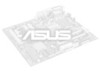
... Cards 5. WARNING! Computer motherboards and expansion cards contain very delicate Integrated Circuit (IC) chips. Install memory modules 3. Setup the BIOS Software 3.4 Motherboard Settings This section tells you install or remove any component, place the components on them due to touch the IC... object, such as the power supply case, before handling computer components. 3. H/W SETUP Motherboard Settings TUV4X ® TUV4X Onboard LED LED ON Standby Power OFF Powered Off 16 ASUS TUV4X User's Manual To avoid damaging them . 4. Hold components by the edges and try not to...
... Cards 5. WARNING! Computer motherboards and expansion cards contain very delicate Integrated Circuit (IC) chips. Install memory modules 3. Setup the BIOS Software 3.4 Motherboard Settings This section tells you install or remove any component, place the components on them due to touch the IC... object, such as the power supply case, before handling computer components. 3. H/W SETUP Motherboard Settings TUV4X ® TUV4X Onboard LED LED ON Standby Power OFF Powered Off 16 ASUS TUV4X User's Manual To avoid damaging them . 4. Hold components by the edges and try not to...

TUV4X User Manual
Page 17
Setting JEN Enable (JumperFree) [2-3] (default) Disable (Jumper) [1-2] DIP_SW ON 12345678 OFF TUV4X ® JEN 12 Jumper Mode TUV4X JumperFree™ Mode Setting 23 JumperFree Mode (Default) NOTE: In JumperFree™ mode, set all the ... white block represents the switch's position. HARDWARE SETUP Motherboard Frequency Settings (DIP Switches) The motherboard frequency is adjusted through the BIOS setup (see 4.4 Advanced Menu). ASUS TUV4X User's Manual 17 The JumperFree™ mode allows processor settings to be made through the DIP switches. < Frequency Multiple ...
Setting JEN Enable (JumperFree) [2-3] (default) Disable (Jumper) [1-2] DIP_SW ON 12345678 OFF TUV4X ® JEN 12 Jumper Mode TUV4X JumperFree™ Mode Setting 23 JumperFree Mode (Default) NOTE: In JumperFree™ mode, set all the ... white block represents the switch's position. HARDWARE SETUP Motherboard Frequency Settings (DIP Switches) The motherboard frequency is adjusted through the BIOS setup (see 4.4 Advanced Menu). ASUS TUV4X User's Manual 17 The JumperFree™ mode allows processor settings to be made through the DIP switches. < Frequency Multiple ...
TUV4X User Manual
Page 21
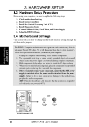
...its default setting for better system stability. 5) Clear RTC RAM These two solder points allow you to select the voltage supplied to Clear CMOS ASUS TUV4X User's Manual 21 As much as system passwords, is powered by erasing the CMOS RTC RAM data. To erase the RTC RAM: (1) ...the computer, (4) hold down the key during the boot process and enter BIOS setup to 3.6V. When system overclocking requires a higher voltage, set this jumper to re-enter data. 3. TUV4X ® VIO 12 23 Normal 3.60 Volt TUV4X VIO Setting WARNING! You can clear the CMOS memory of system components. ...
...its default setting for better system stability. 5) Clear RTC RAM These two solder points allow you to select the voltage supplied to Clear CMOS ASUS TUV4X User's Manual 21 As much as system passwords, is powered by erasing the CMOS RTC RAM data. To erase the RTC RAM: (1) ...the computer, (4) hold down the key during the boot process and enter BIOS setup to 3.6V. When system overclocking requires a higher voltage, set this jumper to re-enter data. 3. TUV4X ® VIO 12 23 Normal 3.60 Volt TUV4X VIO Setting WARNING! You can clear the CMOS memory of system components. ...
TUV4X User Manual
Page 23
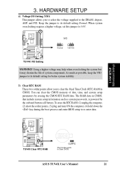
...that have more than EDO (Extended Data Output) chips. • BIOS shows SDRAM memory on bootup screen. • Single-sided DIMMs come... registered support). double-sided come in 32, 64, 128, 256, 512MB. H/W SETUP System Memory 3. ASUS TUV4X User's Manual 23 One side (with higher pin density than 18 chips are available for 3.3Volt (power level... 3.5.1 General DIMM Notes • DIMMs that the DIMM you use only PC100-/PC133- 3. compliant DIMMs. • ASUS motherboards support Serial Presence Detect (SPD) DIMMs. This is the memory of 32MB up one row on this motherboard. ...
...that have more than EDO (Extended Data Output) chips. • BIOS shows SDRAM memory on bootup screen. • Single-sided DIMMs come... registered support). double-sided come in 32, 64, 128, 256, 512MB. H/W SETUP System Memory 3. ASUS TUV4X User's Manual 23 One side (with higher pin density than 18 chips are available for 3.3Volt (power level... 3.5.1 General DIMM Notes • DIMMs that the DIMM you use only PC100-/PC133- 3. compliant DIMMs. • ASUS motherboards support Serial Presence Detect (SPD) DIMMs. This is the memory of 32MB up one row on this motherboard. ...

TUV4X User Manual
Page 27
... and press firmly until the card fits in the next section when installing expansion cards. Change the necessary BIOS settings, if any necessary hardware settings for the card before installing it. 2. H/W SETUP Expansion Cards ASUS TUV4X User's Manual 27 3. Failure to do so may need to change the settings.) 7. Secure the card to...
... and press firmly until the card fits in the next section when installing expansion cards. Change the necessary BIOS settings, if any necessary hardware settings for the card before installing it. 2. H/W SETUP Expansion Cards ASUS TUV4X User's Manual 27 3. Failure to do so may need to change the settings.) 7. Secure the card to...

TUV4X User Manual
Page 35
...devices, purchase another for the jumper settings. TIP: You may configure two hard disks to the UltraDMA/100/66 master device. BIOS supports specific device bootup (see 4.6. Primary IDE Connector Secondary IDE Connector 3. If you must configure the second drive as a ...cable to the hard disk documentation for the secondary IDE connector. PIN 1 ASUS TUV4X User's Manual 35 This prevents incorrect orientation when you connect the cables. 2. Refer to PIN 1. H/W SETUP Connectors TUV4X ® TUV4X IDE Connectors NOTE: Orient the red markings (usually zigzag) on the UltraDMA...
...devices, purchase another for the jumper settings. TIP: You may configure two hard disks to the UltraDMA/100/66 master device. BIOS supports specific device bootup (see 4.6. Primary IDE Connector Secondary IDE Connector 3. If you must configure the second drive as a ...cable to the hard disk documentation for the secondary IDE connector. PIN 1 ASUS TUV4X User's Manual 35 This prevents incorrect orientation when you connect the cables. 2. Refer to PIN 1. H/W SETUP Connectors TUV4X ® TUV4X IDE Connectors NOTE: Orient the red markings (usually zigzag) on the UltraDMA...

TUV4X User Manual
Page 43
...LED feature requires an ACPI OS and driver support. 19) System Management Interrupt Connector (2-pin SMI) This 2-pin connector allows you turn on the BIOS or OS settings. Attach the casemounted suspend switch this 2-pin connector. 20) ATX Power Switch / Soft-Off Switch Connector (2-pin PWR.SW) ... is for more than 4 seconds turns the system off the power switch. HARDWARE SETUP The following 20-pin PANEL illustration is a preferred method ASUS TUV4X User's Manual 43 Pressing the button switches the system between ON and SLEEP, or ON and SOFT OFF, depending on the system power, and...
...LED feature requires an ACPI OS and driver support. 19) System Management Interrupt Connector (2-pin SMI) This 2-pin connector allows you turn on the BIOS or OS settings. Attach the casemounted suspend switch this 2-pin connector. 20) ATX Power Switch / Soft-Off Switch Connector (2-pin PWR.SW) ... is for more than 4 seconds turns the system off the power switch. HARDWARE SETUP The following 20-pin PANEL illustration is a preferred method ASUS TUV4X User's Manual 43 Pressing the button switches the system between ON and SLEEP, or ON and SOFT OFF, depending on the system power, and...

TUV4X User Manual
Page 44
... standby feature,the monitor LED may have failed a power-on , hold down with ). 3. Award BIOS Beep Codes Beep One short beep when displaying logo Long beeps in some systems, marked with ATX power supplies. 44 ASUS TUV4X User's Manual At power on test. If you can now safely turn off (in an.... Connect the power cord to switch on the power supply as well as press the ATX power switch on the front panel of the chassis.) 6. BIOS SETUP. * Powering Off the computer: You must first exit or shut down the computer? 33.. Monitor b. For ATX power supplies, you use Windows ...
... standby feature,the monitor LED may have failed a power-on , hold down with ). 3. Award BIOS Beep Codes Beep One short beep when displaying logo Long beeps in some systems, marked with ATX power supplies. 44 ASUS TUV4X User's Manual At power on test. If you can now safely turn off (in an.... Connect the power cord to switch on the power supply as well as press the ATX power switch on the front panel of the chassis.) 6. BIOS SETUP. * Powering Off the computer: You must first exit or shut down the computer? 33.. Monitor b. For ATX power supplies, you use Windows ...

TUV4X User Manual
Page 45
...created. NOTE: AFLASH works only in DOS mode. Type COPY D:\AFLASH\AFLASH.EXE A:\ (assuming D is recommended that updates the BIOS by uploading a new BIOS file to the programmable flash ROM on the upper left-hand corner of your screen during bootup. Reboot the computer from the ...to reinstall the BIOS later. NOTE: BIOS setup must specify "Floppy" as the first item in the DOS prompt within Windows and does not work with a Flash Memory Writer utility (AFLASH.EXE) to the boot disk you reboot using a floppy disk. 3. BIOS SETUP Updating BIOS IMPORTANT! ASUS TUV4X User's Manual 45...
...created. NOTE: AFLASH works only in DOS mode. Type COPY D:\AFLASH\AFLASH.EXE A:\ (assuming D is recommended that updates the BIOS by uploading a new BIOS file to the programmable flash ROM on the upper left-hand corner of your screen during bootup. Reboot the computer from the ...to reinstall the BIOS later. NOTE: BIOS setup must specify "Floppy" as the first item in the DOS prompt within Windows and does not work with a Flash Memory Writer utility (AFLASH.EXE) to the boot disk you reboot using a floppy disk. 3. BIOS SETUP Updating BIOS IMPORTANT! ASUS TUV4X User's Manual 45...

TUV4X User Manual
Page 46
The Save Current BIOS To File screen appears. 6. BIOS SETUP Updating BIOS 46 ASUS TUV4X User's Manual Type a filename and the path, for example, A:\XXX-XX.XXX and then press . 4. 4. Save Current BIOS to File from the Main menu and press . Select 1. BIOS SETUP 5.
The Save Current BIOS To File screen appears. 6. BIOS SETUP Updating BIOS 46 ASUS TUV4X User's Manual Type a filename and the path, for example, A:\XXX-XX.XXX and then press . 4. 4. Save Current BIOS to File from the Main menu and press . Select 1. BIOS SETUP 5.

TUV4X User Manual
Page 47
...filename of your motherboard having more problems! 1. Download an updated ASUS BIOS file from the floppy disk. 3. When prompted to confirm the BIOS update, press Y to the boot floppy disk you know that the new BIOS revision will solve your problems. Careless updating can result in ...your new BIOS and the path, for details) and save to start the update. 4. BIOS SETUP 4.1.2 Updating BIOS Procedures WARNING! BIOS SETUP Updating BIOS ASUS TUV4X User's Manual 47 At the "A:\" ...
...filename of your motherboard having more problems! 1. Download an updated ASUS BIOS file from the floppy disk. 3. When prompted to confirm the BIOS update, press Y to the boot floppy disk you know that the new BIOS revision will solve your problems. Careless updating can result in ...your new BIOS and the path, for details) and save to start the update. 4. BIOS SETUP 4.1.2 Updating BIOS Procedures WARNING! BIOS SETUP Updating BIOS ASUS TUV4X User's Manual 47 At the "A:\" ...
TUV4X User Manual
Page 48
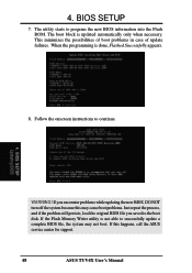
... case of update failures. If you encounter problems while updating the new BIOS, DO NOT turn off the system because this happens, call the ASUS service center for support. 48 ASUS TUV4X User's Manual 4. Follow the onscreen instructions to program the new BIOS information into the Flash ROM. The utility starts to continue. 4. If this...
... case of update failures. If you encounter problems while updating the new BIOS, DO NOT turn off the system because this happens, call the ASUS service center for support. 48 ASUS TUV4X User's Manual 4. Follow the onscreen instructions to program the new BIOS information into the Flash ROM. The utility starts to continue. 4. If this...


