TUSI-M User Manual
Page 2
... USE ONLY, AND ARE SUBJECT TO CHANGE AT ANY TIME WITHOUT NOTICE, AND SHOULD NOT BE CONSTRUED AS A COMMITMENT BY ASUS. Product Name: ASUS TUSI-M Manual Revision: 1.00 E894B Release Date: October 2001 2 ASUS TUSI-M User's Manual or (2) the serial number of the manual revision number. Manual revisions are released for each product design represented...
... USE ONLY, AND ARE SUBJECT TO CHANGE AT ANY TIME WITHOUT NOTICE, AND SHOULD NOT BE CONSTRUED AS A COMMITMENT BY ASUS. Product Name: ASUS TUSI-M Manual Revision: 1.00 E894B Release Date: October 2001 2 ASUS TUSI-M User's Manual or (2) the serial number of the manual revision number. Manual revisions are released for each product design represented...
TUSI-M User Manual
Page 3
... +886-2-2894-3447 ext. 111 Fax: +886-2-2890-7698 Email: tsd@asus.com.tw Newsgroup: news2.asus.com.tw WWW: www.asus.com.tw FTP: ftp.asus.com.tw/pub/ASUS ASUS COMPUTER INTERNATIONAL (America) Marketing Address: 6737 Mowry Avenue, Mowry Business Center, ...ASUS ASUS COMPUTER GmbH (Europe) Marketing Address: Harkort Str. 25, 40880 Ratingen, BRD, Germany Telephone: 49-2102-445011 Fax: 49-2102-442066 Email: [email protected] Technical Support Hotline: 49-2102-499712 BBS: 49-2102-448690 Email: [email protected] WWW: www.asuscom.de FTP: ftp.asuscom.de/pub/ASUSCOM ASUS TUSI...
... +886-2-2894-3447 ext. 111 Fax: +886-2-2890-7698 Email: tsd@asus.com.tw Newsgroup: news2.asus.com.tw WWW: www.asus.com.tw FTP: ftp.asus.com.tw/pub/ASUS ASUS COMPUTER INTERNATIONAL (America) Marketing Address: 6737 Mowry Avenue, Mowry Business Center, ...ASUS ASUS COMPUTER GmbH (Europe) Marketing Address: Harkort Str. 25, 40880 Ratingen, BRD, Germany Telephone: 49-2102-445011 Fax: 49-2102-442066 Email: [email protected] Technical Support Hotline: 49-2102-499712 BBS: 49-2102-448690 Email: [email protected] WWW: www.asuscom.de FTP: ftp.asuscom.de/pub/ASUSCOM ASUS TUSI...
TUSI-M User Manual
Page 4
FEATURES 8 2.1 The ASUS TUSI-M 8 2.1.1 Specifications 8 2.1.2 Specifications-Optional Components 9 2.1.3 Performance 10 2.1.4 Intelligence 11 2.2 TUSI-M Motherboard Components 12 3. BIOS SETUP 39 4.1 Managing and Updating Your BIOS 39 4.1.1 ...Bar 44 4.3 Main Menu 46 4.3.1 Primary & Secondary Master/Slave 47 4.3.2 Keyboard Features 50 4 ASUS TUSI-M User's Manual INTRODUCTION 7 1.1 How This Manual Is Organized 7 1.2 Item Checklist 7 2. HARDWARE SETUP 14 3.1 TUSI-M Motherboard Layout 14 3.2 Layout Contents 15 3.3 Hardware Setup Procedure 16 3.4 Motherboard Settings 16 3.5...
FEATURES 8 2.1 The ASUS TUSI-M 8 2.1.1 Specifications 8 2.1.2 Specifications-Optional Components 9 2.1.3 Performance 10 2.1.4 Intelligence 11 2.2 TUSI-M Motherboard Components 12 3. BIOS SETUP 39 4.1 Managing and Updating Your BIOS 39 4.1.1 ...Bar 44 4.3 Main Menu 46 4.3.1 Primary & Secondary Master/Slave 47 4.3.2 Keyboard Features 50 4 ASUS TUSI-M User's Manual INTRODUCTION 7 1.1 How This Manual Is Organized 7 1.2 Item Checklist 7 2. HARDWARE SETUP 14 3.1 TUSI-M Motherboard Layout 14 3.2 Layout Contents 15 3.3 Hardware Setup Procedure 16 3.4 Motherboard Settings 16 3.5...
TUSI-M User Manual
Page 5
APPENDIX 91 7.1 Glossary 91 INDEX 95 ASUS TUSI-M User's Manual 5 SOFTWARE REFERENCE 75 6.1 ASUS PC Probe 75 6.2 CyberLink PowerPlayer SE 81 6.3 CyberLink VideoLive Mail 81 6.4 ASUS Live Update 83 6.5 3Deep Color Tuner 84 6.6 ALi SiS Display Properties Menu 86 7. CONTENTS 4.4 Advanced Menu 52 4.4.1 Chip Configuration 55 4.4.2 I/O Device Configuration 58 4.4.3 PCI ... 63 4.5.1 Power Up Control 65 4.5.2 Hardware Monitor 67 4.6 Boot Menu 68 4.7 Exit Menu 70 5. SOFTWARE SETUP 73 5.1 Install Operating System 73 5.2 Start Windows 73 5.3 TUSI-M Motherboard Support CD 74 6.
APPENDIX 91 7.1 Glossary 91 INDEX 95 ASUS TUSI-M User's Manual 5 SOFTWARE REFERENCE 75 6.1 ASUS PC Probe 75 6.2 CyberLink PowerPlayer SE 81 6.3 CyberLink VideoLive Mail 81 6.4 ASUS Live Update 83 6.5 3Deep Color Tuner 84 6.6 ALi SiS Display Properties Menu 86 7. CONTENTS 4.4 Advanced Menu 52 4.4.1 Chip Configuration 55 4.4.2 I/O Device Configuration 58 4.4.3 PCI ... 63 4.5.1 Power Up Control 65 4.5.2 Hardware Monitor 67 4.6 Boot Menu 68 4.7 Exit Menu 70 5. SOFTWARE SETUP 73 5.1 Install Operating System 73 5.2 Start Windows 73 5.3 TUSI-M Motherboard Support CD 74 6.
TUSI-M User Manual
Page 6
... complies with manufacturer's instructions, may cause undesired operation. Cet appareil numérique de la classe B est conforme à la norme NMB-003 du Canada. 6 ASUS TUSI-M User's Manual WARNING!
... complies with manufacturer's instructions, may cause undesired operation. Cet appareil numérique de la classe B est conforme à la norme NMB-003 du Canada. 6 ASUS TUSI-M User's Manual WARNING!
TUSI-M User Manual
Page 7
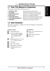
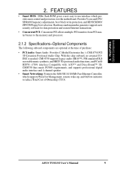
... 1. 1. HARDWARE SETUP 4. APPENDIX Manual information and checklist Production information and specifications Intructions on setting up the motherboard. Package Contents (1) ASUS Motherboard (1) 40-pin 80-conductor ribbon cable for internal UltraDMA/ 66 or UltraDMA/33 IDE drives (1) Ribbon cable for the included ...(2) 3.5" floppy disk drives (1) I/O Shield (1) Bag of spare jumpers (1) Support drivers and utilities (1) This Motherboard User's Manual Optional Items ASUS 3-port USB connector set with bracket ASUS consumer infrared set Modem riser ASUS TUSI-M User's Manual 7
... 1. 1. HARDWARE SETUP 4. APPENDIX Manual information and checklist Production information and specifications Intructions on setting up the motherboard. Package Contents (1) ASUS Motherboard (1) 40-pin 80-conductor ribbon cable for internal UltraDMA/ 66 or UltraDMA/33 IDE drives (1) Ribbon cable for the included ...(2) 3.5" floppy disk drives (1) I/O Shield (1) Bag of spare jumpers (1) Support drivers and utilities (1) This Motherboard User's Manual Optional Items ASUS 3-port USB connector set with bracket ASUS consumer infrared set Modem riser ASUS TUSI-M User's Manual 7
TUSI-M User Manual
Page 8
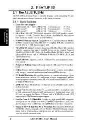
... on two channels. ler supports a 133MHz Front Side Bus (FSB) and UltraDMA/100, which is carefully designed for virtually automatic setup. 8 ASUS TUSI-M User's Manual FEATURES Specifications 2. Supports UltraDMA/100/66/33, PIO Modes 3 & 4 and Bus Master IDE DMA Mode 2, and Enhanced IDE...; 100MHz FSB Tualatin core FC-PGA2 • SiS AGPset: SiS 630ET AGPset with EPP and ECP capabilities. FEATURES 2.1 The ASUS TUSI-M The ASUS TUSI-M motherboard is used to physically transport commands and information between SMBus devices. • PC Health Monitoring: Provides an easy way...
... on two channels. ler supports a 133MHz Front Side Bus (FSB) and UltraDMA/100, which is carefully designed for virtually automatic setup. 8 ASUS TUSI-M User's Manual FEATURES Specifications 2. Supports UltraDMA/100/66/33, PIO Modes 3 & 4 and Bus Master IDE DMA Mode 2, and Enhanced IDE...; 100MHz FSB Tualatin core FC-PGA2 • SiS AGPset: SiS 630ET AGPset with EPP and ECP capabilities. FEATURES 2.1 The ASUS TUSI-M The ASUS TUSI-M motherboard is used to physically transport commands and information between SMBus devices. • PC Health Monitoring: Provides an easy way...
TUSI-M User Manual
Page 9
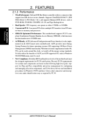
... transfers from PCI master busses to the memory and processor. 2.1.2 Specifications-Optional Components The following onboard components are optional at the time of Ownership (TCO). ASUS TUSI-M User's Manual 9 Provides Vcore and CPU/ SDRAM frequency adjustments, boot block write protection, and HD/SCSI/MO/ ZIP/CD/Floppy boot selection. With this chip...
... transfers from PCI master busses to the memory and processor. 2.1.2 Specifications-Optional Components The following onboard components are optional at the time of Ownership (TCO). ASUS TUSI-M User's Manual 9 Provides Vcore and CPU/ SDRAM frequency adjustments, boot block write protection, and HD/SCSI/MO/ ZIP/CD/Floppy boot selection. With this chip...
TUSI-M User Manual
Page 10
...FEATURES Performance 2. With these features implemented in two channels. The new PC 99 requirements for systems and components are based on all ASUS smart series motherboards. Color-coded connectors and descriptive icons make identification easy as DVD-ROM, CD-ROM, CD-R/RW, LS-120...Supports UltraDMA100//66/33, (IDE DMA Mode 2), PIO Modes 3 & 4, and supports Enhanced IDE devices, such as required by PC 99. 10 ASUS TUSI-M User's Manual FEATURES 2.1.3 Performance • UltraPerformance: Onboard IDE Bus Master controller with two connectors that support four IDE devices in the OS, PCs ...
...FEATURES Performance 2. With these features implemented in two channels. The new PC 99 requirements for systems and components are based on all ASUS smart series motherboards. Color-coded connectors and descriptive icons make identification easy as DVD-ROM, CD-ROM, CD-R/RW, LS-120...Supports UltraDMA100//66/33, (IDE DMA Mode 2), PIO Modes 3 & 4, and supports Enhanced IDE devices, such as required by PC 99. 10 ASUS TUSI-M User's Manual FEATURES 2.1.3 Performance • UltraPerformance: Onboard IDE Bus Master controller with two connectors that support four IDE devices in the OS, PCs ...
TUSI-M User Manual
Page 11
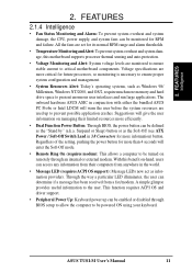
... setting, pushing the power button for future processors, so monitoring is necessary to present enormous user interfaces and run large applications. ASUS TUSI-M User's Manual 11 FEATURES 2.1.4 Intelligence • Fan Status Monitoring and Alarm: To prevent system overheat and system damage, the... will give the user information on remotely through BIOS setup to allow the computer to critical motherboard components. The onboard hardware ASUS ASIC in 3.8 Connectors for RPM and failure. With this motherboard supports processor thermal sensing and auto-protection. • Voltage...
... setting, pushing the power button for future processors, so monitoring is necessary to present enormous user interfaces and run large applications. ASUS TUSI-M User's Manual 11 FEATURES 2.1.4 Intelligence • Fan Status Monitoring and Alarm: To prevent system overheat and system damage, the... will give the user information on remotely through BIOS setup to allow the computer to critical motherboard components. The onboard hardware ASUS ASIC in 3.8 Connectors for RPM and failure. With this motherboard supports processor thermal sensing and auto-protection. • Voltage...
TUSI-M User Manual
Page 12
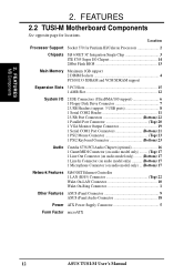
Location Processor Support Socket 370 for locations. FEATURES 2.2 TUSI-M Motherboard Components See opposite page for Pentium III/Celeron Processors 2 Chipsets SiS 630ET 3C Integration Single Chip 3 ITE 8705 Super I/O Chipset 14 2Mbit ...only) ... (Bottom) 17 Network Features SiS630ET Ethernet Controller 1 LAN (RJ45) Connector Top) 22 Wake-On-LAN Connector 10 Wake-On-Ring Connector 1 Other Features ASUS iPanel Connector 9 ASUS iPanel Audio Connector 18 Power ATX Power Supply Connector 5 Form Factor microATX 12 ASUS TUSI-M User's Manual 2. FEATURES MB Components 2.
Location Processor Support Socket 370 for locations. FEATURES 2.2 TUSI-M Motherboard Components See opposite page for Pentium III/Celeron Processors 2 Chipsets SiS 630ET 3C Integration Single Chip 3 ITE 8705 Super I/O Chipset 14 2Mbit ...only) ... (Bottom) 17 Network Features SiS630ET Ethernet Controller 1 LAN (RJ45) Connector Top) 22 Wake-On-LAN Connector 10 Wake-On-Ring Connector 1 Other Features ASUS iPanel Connector 9 ASUS iPanel Audio Connector 18 Power ATX Power Supply Connector 5 Form Factor microATX 12 ASUS TUSI-M User's Manual 2. FEATURES MB Components 2.
TUSI-M User Manual
Page 14
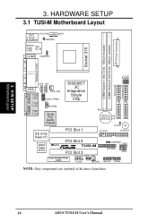
HARDWARE SETUP 3.1 TUSI-M Motherboard Layout 01 PS/2 CPU_FAN T: Mouse B: Keyboard PWRTMP WOR Bottom: Top: USB1 USB2 RJ-45 COM1 USBPWR1 ATX Power Connector DIMM Socket 2 (64/72-bit, ...-bit PCI Audio Chipset Row 0 1 2 3 CR2032 3V Lithium Cell CMOS Power CLRTC ITE 8705 Super I/O 2Mbit Flash BIOS PCI Slot 1 FLOPPY BUZZER PCI Slot 2 JEN R TUSI-M PCI Slot 3 USBPWR0 USB1 AFPANEL USB2 Audio Modem Riser (AMR) WOL_CON COM2 CH_FAN IDELED PANEL NOTE: Gray components are optional at the time of purchase...
HARDWARE SETUP 3.1 TUSI-M Motherboard Layout 01 PS/2 CPU_FAN T: Mouse B: Keyboard PWRTMP WOR Bottom: Top: USB1 USB2 RJ-45 COM1 USBPWR1 ATX Power Connector DIMM Socket 2 (64/72-bit, ...-bit PCI Audio Chipset Row 0 1 2 3 CR2032 3V Lithium Cell CMOS Power CLRTC ITE 8705 Super I/O 2Mbit Flash BIOS PCI Slot 1 FLOPPY BUZZER PCI Slot 2 JEN R TUSI-M PCI Slot 3 USBPWR0 USB1 AFPANEL USB2 Audio Modem Riser (AMR) WOL_CON COM2 CH_FAN IDELED PANEL NOTE: Gray components are optional at the time of purchase...
TUSI-M User Manual
Page 15
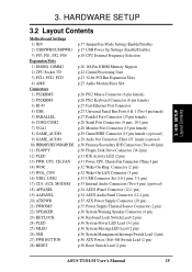
... (2 pin) p.32 Wake-On-LAN Connector (3 pin) p.33 USB Connector Set (10-1 pins, 5-1 pin) p.33 Internal Audio Connectors (Two 4 pin) (optional) p.34 ASUS iPanel Connector (12-1 pin) p.34 ASUS Audio Panel Connector (12-1 pin) p.35 ATX Power Supply Connector (20 pin) p.35 Power Supply Thermal Sensor Connector (2 pin) p.36 System Warning Speaker...) p.36 System MessageLED Lead (2 pin) p.36 System Management Interrupt Switch Lead (2 pin) p.36 ATX Power / Soft-Off Switch Lead (2 pin) p.36 Reset Switch Lead (2 pin) ASUS TUSI-M User's Manual 15
... (2 pin) p.32 Wake-On-LAN Connector (3 pin) p.33 USB Connector Set (10-1 pins, 5-1 pin) p.33 Internal Audio Connectors (Two 4 pin) (optional) p.34 ASUS iPanel Connector (12-1 pin) p.34 ASUS Audio Panel Connector (12-1 pin) p.35 ATX Power Supply Connector (20 pin) p.35 Power Supply Thermal Sensor Connector (2 pin) p.36 System Warning Speaker...) p.36 System MessageLED Lead (2 pin) p.36 System Management Interrupt Switch Lead (2 pin) p.36 ATX Power / Soft-Off Switch Lead (2 pin) p.36 Reset Switch Lead (2 pin) ASUS TUSI-M User's Manual 15
TUSI-M User Manual
Page 16
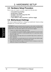
... or remove the ATX power connector on the bag that the ATX power supply is switched off before handling computer components. H/W SETUP Motherboard Settings 16 ASUS TUSI-M User's Manual Computer motherboards and expansion cards contain very delicate Integrated Circuit (IC) chips. Hold components by the edges and try not to a metal object...
... or remove the ATX power connector on the bag that the ATX power supply is switched off before handling computer components. H/W SETUP Motherboard Settings 16 ASUS TUSI-M User's Manual Computer motherboards and expansion cards contain very delicate Integrated Circuit (IC) chips. Hold components by the edges and try not to a metal object...
TUSI-M User Manual
Page 17
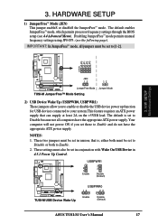
... Mode (JEN) This jumper enableS or disableS the JumperFree™ mode. H/W SETUP Motherboard Settings 01 01 3 2 1 TUSI-M JEN 12 12 JumperFree Mode Jumper Mode TUSI-M JumperFree™ Mode Setting 2) USB Device Wake Up (USBPWR0, USBPWR1) These jumpers allow you set to Disable because not ... at least 2A on the +5VSB lead. NOTES: 1. USBPWR1 2 1 Enable 3 2 Disable (Default) ® TUSI-M TUSI-M USB Device Wake Up USBPWR0 12 23 Enable Disable (Default) ASUS TUSI-M User's Manual 17 JP3 JP1 JP2 JP0 3. The default is , either both to Disable or both must also be...
... Mode (JEN) This jumper enableS or disableS the JumperFree™ mode. H/W SETUP Motherboard Settings 01 01 3 2 1 TUSI-M JEN 12 12 JumperFree Mode Jumper Mode TUSI-M JumperFree™ Mode Setting 2) USB Device Wake Up (USBPWR0, USBPWR1) These jumpers allow you set to Disable because not ... at least 2A on the +5VSB lead. NOTES: 1. USBPWR1 2 1 Enable 3 2 Disable (Default) ® TUSI-M TUSI-M USB Device Wake Up USBPWR0 12 23 Enable Disable (Default) ASUS TUSI-M User's Manual 17 JP3 JP1 JP2 JP0 3. The default is , either both to Disable or both must also be...
TUSI-M User Manual
Page 18
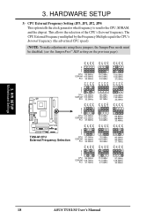
....5MHz 133.3MHz 133.3MHz 33.3MHz 66.8MHz 66.8MHz 33.4MHz JP2 JP1 JP3 JP0 JP2 JP1 JP3 JP0 JP2 JP1 JP3 ® TUSI-M TUSI-M CPU External Frequency Selection 3 2 1 CPU SDRAM PCI 97.0MHz 97.0MHz 32.3MHz 70.0MHz 105.0MHz 35.0MHz 95.0MHz 95.0MHz 31.7MHz... JP3 3 2 1 CPU 95.0MHz SDRAM 126.7MHz PCI 31.7MHz 112.0MHz 112.0MHz 37.3MHz 97.0MHz 129.3MHz 32.2MHz JP0 JP0 18 ASUS TUSI-M User's Manual This allows the selection of the CPU's External frequency. 3. H/W SETUP Motherboard Settings 3.
....5MHz 133.3MHz 133.3MHz 33.3MHz 66.8MHz 66.8MHz 33.4MHz JP2 JP1 JP3 JP0 JP2 JP1 JP3 JP0 JP2 JP1 JP3 ® TUSI-M TUSI-M CPU External Frequency Selection 3 2 1 CPU SDRAM PCI 97.0MHz 97.0MHz 32.3MHz 70.0MHz 105.0MHz 35.0MHz 95.0MHz 95.0MHz 31.7MHz... JP3 3 2 1 CPU 95.0MHz SDRAM 126.7MHz PCI 31.7MHz 112.0MHz 112.0MHz 37.3MHz 97.0MHz 129.3MHz 32.2MHz JP0 JP0 18 ASUS TUSI-M User's Manual This allows the selection of the CPU's External frequency. 3. H/W SETUP Motherboard Settings 3.
TUSI-M User Manual
Page 19
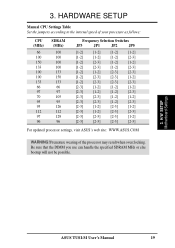
... of the processor may result when overclocking. H/W SETUP Motherboard Settings ASUS TUSI-M User's Manual 19 Premature wearing of your processor as follows: ... [1-2] [1-2] [2-3] [2-3] [1-2] [2-3] [2-3] [1-2] [1-2] [2-3] [2-3] [2-3] [2-3] [1-2] [1-2] [1-2] [2-3] [1-2] [1-2] [2-3] [2-3] [2-3] [1-2] [1-2] [2-3] [2-3] [1-2] [2-3] [2-3] [1-2] [2-3] [1-2] [2-3] [1-2] [2-3] [2-3] [2-3] [2-3] [2-3] [1-2] [2-3] [2-3] [2-3] [2-3] For updated processor settings, visit ASUS's web site: WWW.ASUS.COM WARNING! Be sure that the DIMM you use can handle the specified SDRAM MHz or else bootup will...
... of the processor may result when overclocking. H/W SETUP Motherboard Settings ASUS TUSI-M User's Manual 19 Premature wearing of your processor as follows: ... [1-2] [1-2] [2-3] [2-3] [1-2] [2-3] [2-3] [1-2] [1-2] [2-3] [2-3] [2-3] [2-3] [1-2] [1-2] [1-2] [2-3] [1-2] [1-2] [2-3] [2-3] [2-3] [1-2] [1-2] [2-3] [2-3] [1-2] [2-3] [2-3] [1-2] [2-3] [1-2] [2-3] [1-2] [2-3] [2-3] [2-3] [2-3] [2-3] [1-2] [2-3] [2-3] [2-3] [2-3] For updated processor settings, visit ASUS's web site: WWW.ASUS.COM WARNING! Be sure that the DIMM you use can handle the specified SDRAM MHz or else bootup will...
TUSI-M User Manual
Page 20
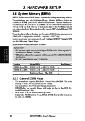
... density than EDO (Ex- One side (with 9 chips per side (standard 8 chips/side + 1 ECC chip). double-sided come in 32, 64, 128, 256, 512MB. 20 ASUS TUSI-M User's Manual H/W SETUP System Memory 3. This motherboard also supports NEC's Virtual Channel (VC) SDRAMs. To use the chipset's Error Checking and Correction (ECC) feature, you...
... density than EDO (Ex- One side (with 9 chips per side (standard 8 chips/side + 1 ECC chip). double-sided come in 32, 64, 128, 256, 512MB. 20 ASUS TUSI-M User's Manual H/W SETUP System Memory 3. This motherboard also supports NEC's Virtual Channel (VC) SDRAMs. To use the chipset's Error Checking and Correction (ECC) feature, you...
TUSI-M User Manual
Page 21
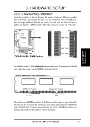
... the DIMM module will only fit in the orientation shown. You must be 3.3V Unbuffered for this motherboard. This motherboard supports four clock signals. ASUS TUSI-M User's Manual 21 HARDWARE SETUP 3.5.2 DIMM Memory Installation Insert the module(s) as shown. DIMM modules are different on both sides. To determine the...type, check the notches on the DIMMs (see figure below). 168-Pin DIMM Notch Key Definitions (3.3V) 3. 3. Lock 88 Pins 01 ® TUSI-M TUSI-M 168-Pin DIMM Sockets 60 Pins 20 Pins The DIMMs must ask your retailer the correct DIMM type before purchasing.
... the DIMM module will only fit in the orientation shown. You must be 3.3V Unbuffered for this motherboard. This motherboard supports four clock signals. ASUS TUSI-M User's Manual 21 HARDWARE SETUP 3.5.2 DIMM Memory Installation Insert the module(s) as shown. DIMM modules are different on both sides. To determine the...type, check the notches on the DIMMs (see figure below). 168-Pin DIMM Notch Key Definitions (3.3V) 3. 3. Lock 88 Pins 01 ® TUSI-M TUSI-M 168-Pin DIMM Sockets 60 Pins 20 Pins The DIMMs must ask your retailer the correct DIMM type before purchasing.
TUSI-M User Manual
Page 22
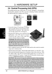
...lever gently sideways away from the socket. With the added weight of the lever handle. A fan and heat- H/W SETUP CPU Notch Celeron ® TUSI-M TUSI-M Socket 370 Pentium III Gold Arrow 1. The socket lever must be fully opened (90 to prevent overheating. If the CPU does not fit, check... corner of the socket base nearest to the tip of the CPU fan and heatsink locking brace, no extra force is not needed. 22 ASUS TUSI-M User's Manual Install an Intel fan heatsink. Connect the CPU fan cable to scrape the motherboard surface when mounting a clamp-style processor fan...
...lever gently sideways away from the socket. With the added weight of the lever handle. A fan and heat- H/W SETUP CPU Notch Celeron ® TUSI-M TUSI-M Socket 370 Pentium III Gold Arrow 1. The socket lever must be fully opened (90 to prevent overheating. If the CPU does not fit, check... corner of the socket base nearest to the tip of the CPU fan and heatsink locking brace, no extra force is not needed. 22 ASUS TUSI-M User's Manual Install an Intel fan heatsink. Connect the CPU fan cable to scrape the motherboard surface when mounting a clamp-style processor fan...


