TUF Z270 MARK 2 Users manual ENGLISH
Page 3
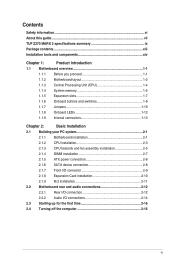
Contents Safety information...vi About this guide...vii TUF Z270 MARK 2 specifications summary ix Package contents...xiii Installation tools and components xiv Chapter 1: ... Basic Installation 2.1 Building your PC system 2-1 2.1.1 Motherboard installation 2-1 2.1.2 CPU installation 2-3 2.1.3 CPU heatsink and fan assembly installation 2-5 2.1.4 DIMM installation 2-7 2.1.5 ATX power connection 2-8 2.1.6 SATA device connection 2-8 2.1.7 Front I/O connector 2-9 2.1.8 Expansion Card installation 2-10 2.1.9 M.2 installation 2-11 2.2 Motherboard rear and audio connections 2-...
Contents Safety information...vi About this guide...vii TUF Z270 MARK 2 specifications summary ix Package contents...xiii Installation tools and components xiv Chapter 1: ... Basic Installation 2.1 Building your PC system 2-1 2.1.1 Motherboard installation 2-1 2.1.2 CPU installation 2-3 2.1.3 CPU heatsink and fan assembly installation 2-5 2.1.4 DIMM installation 2-7 2.1.5 ATX power connection 2-8 2.1.6 SATA device connection 2-8 2.1.7 Front I/O connector 2-9 2.1.8 Expansion Card installation 2-10 2.1.9 M.2 installation 2-11 2.2 Motherboard rear and audio connections 2-...
TUF Z270 MARK 2 Users manual ENGLISH
Page 12
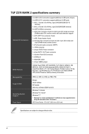
... Wizard, F6 Qfan Control, F3 My Favorites, Last Modified log, F12 PrintScreen and ASUS DRAM SPD (Serial Presence Detect) memory information WfM 2.0, DMI 3.0, WOL by PME, PXE Drivers ASUS Utilities EZ Update Anti-virus software (OEM version) Windows® 10 64-bit Windows...; 7 32/64-bit are only supported when using 6th Generation Intel® Processors ATX Form Factor, 12"x 9.2" (30.5 cm x 23.4 cm) Specifications are subject to change without notice. xii TUF Z270 MARK 2 specifications summary Internal I/O Connectors BIOS Features Manageability Support DVD Operating System Support Form Factor...
... Wizard, F6 Qfan Control, F3 My Favorites, Last Modified log, F12 PrintScreen and ASUS DRAM SPD (Serial Presence Detect) memory information WfM 2.0, DMI 3.0, WOL by PME, PXE Drivers ASUS Utilities EZ Update Anti-virus software (OEM version) Windows® 10 64-bit Windows...; 7 32/64-bit are only supported when using 6th Generation Intel® Processors ATX Form Factor, 12"x 9.2" (30.5 cm x 23.4 cm) Specifications are subject to change without notice. xii TUF Z270 MARK 2 specifications summary Internal I/O Connectors BIOS Features Manageability Support DVD Operating System Support Form Factor...
TUF Z270 MARK 2 Users manual ENGLISH
Page 15
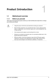
... you proceed Take note of the following precautions before you install or remove any component, ensure that the ATX power supply is switched off or the power cord is detached from the power supply. ASUS TUF Z270 MARK 2 1-1 Failure to do so may cause severe damage to avoid touching the ICs on them. • Whenever...
... you proceed Take note of the following precautions before you install or remove any component, ensure that the ATX power supply is switched off or the power cord is detached from the power supply. ASUS TUF Z270 MARK 2 1-1 Failure to do so may cause severe damage to avoid touching the ICs on them. • Whenever...
TUF Z270 MARK 2 Users manual ENGLISH
Page 17
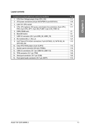
...) Page 1-11 1-18 1-4 1-17 1-5 1-9 1-15 1-21 1-13 1-10 1-19 1-16 1-20 1-20 1-14 ASUS TUF Z270 MARK 2 1-3 Chapter 1 Layout contents Connectors/Jumpers/Buttons and switches/Slots 1. M.2 sockets (M.2_1; USB 2.0 connectors (10-1 pin USB910; M.2_2) 9. System panel connector (20-3 pin PANEL) 12. ATX power connectors (24-pin EATXPWR; 8-pin EATX12V) 3. button 7. USB 3.0 connector (20-1 pin USB3_56...
...) Page 1-11 1-18 1-4 1-17 1-5 1-9 1-15 1-21 1-13 1-10 1-19 1-16 1-20 1-20 1-14 ASUS TUF Z270 MARK 2 1-3 Chapter 1 Layout contents Connectors/Jumpers/Buttons and switches/Slots 1. M.2 sockets (M.2_1; USB 2.0 connectors (10-1 pin USB910; M.2_2) 9. System panel connector (20-3 pin PANEL) 12. ATX power connectors (24-pin EATXPWR; 8-pin EATX12V) 3. button 7. USB 3.0 connector (20-1 pin USB3_56...
TUF Z270 MARK 2 Users manual ENGLISH
Page 32
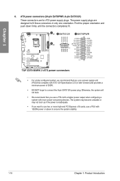
... become unstable or may not boot up if the power is inadequate. • If you want to fit these connectors in only one orientation. ATX power connectors (24-pin EATXPWR; 8-pin EATX12V) These connectors are designed to use two or more high-end PCI Express x16 cards, use a... Chapter 1 6. Otherwise, the system will not boot. • We recommend that you use a power supply unit (PSU) that you use a PSU with ATX 12V Specification 2.0 (or later version) and provides a minimum power of 350W. • DO NOT forget to ensure the system stability. 1-18 Chapter 1: Product Introduction
... become unstable or may not boot up if the power is inadequate. • If you want to fit these connectors in only one orientation. ATX power connectors (24-pin EATXPWR; 8-pin EATX12V) These connectors are designed to use two or more high-end PCI Express x16 cards, use a... Chapter 1 6. Otherwise, the system will not boot. • We recommend that you use a power supply unit (PSU) that you use a PSU with ATX 12V Specification 2.0 (or later version) and provides a minimum power of 350W. • DO NOT forget to ensure the system stability. 1-18 Chapter 1: Product Introduction
TUF Z270 MARK 2 Users manual ENGLISH
Page 33
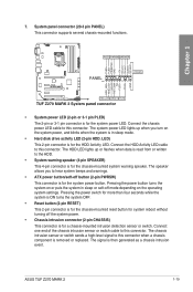
... the power button turns the system on the operating system settings. Connect one end of the chassis intrusion sensor or switch cable to this connector. ASUS TUF Z270 MARK 2 1-19 Connect the HDD Activity LED cable to this connector. The chassis intrusion sensor or switch sends a high-level signal to the HDD. • System... to this connector when a chassis component is for the system power LED. Connect the chassis power LED cable to hear system beeps and warnings. • ATX power button/soft-off button (2-pin PWRSW) This connector is removed or replaced.
... the power button turns the system on the operating system settings. Connect one end of the chassis intrusion sensor or switch cable to this connector. ASUS TUF Z270 MARK 2 1-19 Connect the HDD Activity LED cable to this connector. The chassis intrusion sensor or switch sends a high-level signal to the HDD. • System... to this connector when a chassis component is for the system power LED. Connect the chassis power LED cable to hear system beeps and warnings. • ATX power button/soft-off button (2-pin PWRSW) This connector is removed or replaced.
TUF Z270 MARK 2 Users manual ENGLISH
Page 44
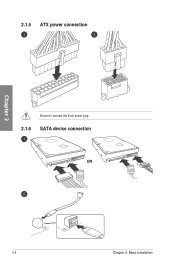
2.1.5 ATX power connection Chapter 2 Ensure to connect the 8-pin power plug. 2.1.6 SATA device connection OR 2-8 Chapter 2: Basic Installation
2.1.5 ATX power connection Chapter 2 Ensure to connect the 8-pin power plug. 2.1.6 SATA device connection OR 2-8 Chapter 2: Basic Installation
TUF Z270 MARK 2 Users manual ENGLISH
Page 52
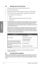
...the system may have failed a power-on the system front panel case lights up. Follow the instructions in the following order: a. If you press the ATX power button. Chapter 2 2.3 Starting up for assistance. After making all switches are running, the BIOS beeps (refer to the BIOS beep codes table)... Installation Connect the power cord to let the system enter the soft-off mode, depending on the screen. External SCSI devices (starting with ATX power supplies, the system LED lights up when you do not see anything within 30 seconds from orange to green after the system LED ...
...the system may have failed a power-on the system front panel case lights up. Follow the instructions in the following order: a. If you press the ATX power button. Chapter 2 2.3 Starting up for assistance. After making all switches are running, the BIOS beeps (refer to the BIOS beep codes table)... Installation Connect the power cord to let the system enter the soft-off mode, depending on the screen. External SCSI devices (starting with ATX power supplies, the system LED lights up when you do not see anything within 30 seconds from orange to green after the system LED ...

