
BIOSUpdateE-Manual English
Page 1
Motherboard BIOS Update and Management
Motherboard BIOS Update and Management
BIOSUpdateE-Manual English
Page 4
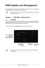
...AI Suite 3 main menu bar. With this utlity, you to automatically update your motherboard's driver, software and firmware Click to find and select the BIOS from file Click to ...select a boot logo Click to automatically update your motherboard's softwares, drivers and the BIOS version easily. Click to update the BIOS EZ Update... BIOS Update and Management Chapter 1: UEFI BIOS - To launch EZ Update, click EZ Update on your motherboard. Graphics Mode 1.1 EZ Update EZ Update is a utility that you can also manually update the saved BIOS...
...AI Suite 3 main menu bar. With this utlity, you to automatically update your motherboard's driver, software and firmware Click to find and select the BIOS from file Click to ...select a boot logo Click to automatically update your motherboard's softwares, drivers and the BIOS version easily. Click to update the BIOS EZ Update... BIOS Update and Management Chapter 1: UEFI BIOS - To launch EZ Update, click EZ Update on your motherboard. Graphics Mode 1.1 EZ Update EZ Update is a utility that you can also manually update the saved BIOS...
BIOSUpdateE-Manual English
Page 6
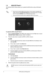
...item under the Exit menu. d) Press to switch to prevent system boot failure! 6 BIOS Update and Management Go to the Tool menu to select ASUS EZ Flash 3 Utility and press to select an Internet connection method, and then press . Follow the steps below to update the BIOS via the... flash disk that you load the BIOS default settings to the section Exit Menu in your motherboard user manual. • Check your Internet connection before updating the BIOS via USB or Internet. 1.3 ASUS EZ Flash 3 The ASUS EZ Flash 3 feature allows you to update the BIOS without using EZ Flash 3: 1. ...
...item under the Exit menu. d) Press to switch to prevent system boot failure! 6 BIOS Update and Management Go to the Tool menu to select ASUS EZ Flash 3 Utility and press to select an Internet connection method, and then press . Follow the steps below to update the BIOS via the... flash disk that you load the BIOS default settings to the section Exit Menu in your motherboard user manual. • Check your Internet connection before updating the BIOS via USB or Internet. 1.3 ASUS EZ Flash 3 The ASUS EZ Flash 3 feature allows you to update the BIOS without using EZ Flash 3: 1. ...

BIOSUpdateE-Manual English
Page 7
...on the system. 2. Doing so can restore a corrupted BIOS file using the motherboard support DVD or a USB flash drive that contains the updated BIOS file. ... during the updating process. BIOS Update and Management 7 Download the latest BIOS file from the ASUS website at www.asus.com. DO NOT shut down or reset the system while updating the BIOS! Recovering the BIOS... To recover the BIOS: 1. The utility automatically checks the devices for the BIOS file. 1.4 ASUS CrashFree BIOS 3 The ASUS CrashFree BIOS 3 is an auto recovery tool that allows you to load default BIOS values. When ...
...on the system. 2. Doing so can restore a corrupted BIOS file using the motherboard support DVD or a USB flash drive that contains the updated BIOS file. ... during the updating process. BIOS Update and Management 7 Download the latest BIOS file from the ASUS website at www.asus.com. DO NOT shut down or reset the system while updating the BIOS! Recovering the BIOS... To recover the BIOS: 1. The utility automatically checks the devices for the BIOS file. 1.4 ASUS CrashFree BIOS 3 The ASUS CrashFree BIOS 3 is an auto recovery tool that allows you to load default BIOS values. When ...
BIOSUpdateE-Manual English
Page 9
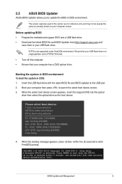
... and in this section are for reference only and may not be exactly the same as the boot device. Before updating BIOS • Prepare the motherboard support DVD and a USB flash drive. • Download the latest BIOS file and BIOS Updater from the DVD/CD. Insert the USB flash drive... with the latest BIOS file and BIOS Updater to update the BIOS in DOS environment. 2.2 ASUS BIOS Updater ASUS BIOS Updater allows you to the USB port. 2. Please select boot device: and to move selection ENTER to select boot ...
... and in this section are for reference only and may not be exactly the same as the boot device. Before updating BIOS • Prepare the motherboard support DVD and a USB flash drive. • Download the latest BIOS file and BIOS Updater from the DVD/CD. Insert the USB flash drive... with the latest BIOS file and BIOS Updater to update the BIOS in DOS environment. 2.2 ASUS BIOS Updater ASUS BIOS Updater allows you to the USB port. 2. Please select boot device: and to move selection ENTER to select boot ...
E11133MBPinDefinition English
Page 1
1 Motherboard Pin Definition E11133 Revised Edition v2 December 2015 E11133_MB_pin_definition_v2.indd 1 2015/12/28 17:21:46
1 Motherboard Pin Definition E11133 Revised Edition v2 December 2015 E11133_MB_pin_definition_v2.indd 1 2015/12/28 17:21:46

E11133MBPinDefinition English
Page 2
Contents Motherboard Pin Definition 1-1 1 Headers...1-3 2 Jumpers...1-4 3 Internal Connectors 1-6 4 Onboard LEDs 1-16 5 Onboard buttons and switches 1-17 1-2 E11133_MB_pin_definition_v2.indd 2 Motherboard Pin Definition 2015/12/28 17:21:46
Contents Motherboard Pin Definition 1-1 1 Headers...1-3 2 Jumpers...1-4 3 Internal Connectors 1-6 4 Onboard LEDs 1-16 5 Onboard buttons and switches 1-17 1-2 E11133_MB_pin_definition_v2.indd 2 Motherboard Pin Definition 2015/12/28 17:21:46

E11133MBPinDefinition English
Page 3
... steps above do not need to clear the RTC when the system hangs due to short the two pins. 3. The signal is removed or replaced. Motherboard Pin Definition E11133_MB_pin_definition_v2.indd 3 1-3 2015/12/28 17:21:46 The onboard button cell battery powers the RAM data in CMOS. After clearing the CMOS...
... steps above do not need to clear the RTC when the system hangs due to short the two pins. 3. The signal is removed or replaced. Motherboard Pin Definition E11133_MB_pin_definition_v2.indd 3 1-3 2015/12/28 17:21:46 The onboard button cell battery powers the RAM data in CMOS. After clearing the CMOS...
E11133MBPinDefinition English
Page 4
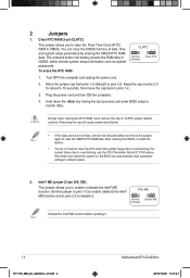
... when clearing the RTC RAM, never remove the cap on pins 2-3 for about 5~10 seconds, then move the jumper again to disable it . 1-4 E11133_MB_pin_definition_v2.indd 4 Motherboard Pin Definition 2015/12/28 17:21:47 You can automatically reset parameter settings to pins 1-2. 3. After clearing the CMOS, reinstall the battery. • You...
... when clearing the RTC RAM, never remove the cap on pins 2-3 for about 5~10 seconds, then move the jumper again to disable it . 1-4 E11133_MB_pin_definition_v2.indd 4 Motherboard Pin Definition 2015/12/28 17:21:47 You can automatically reset parameter settings to pins 1-2. 3. After clearing the CMOS, reinstall the battery. • You...

E11133MBPinDefinition English
Page 5
... LVDS (Default) for each USB port; This feature requires an ATX power supply that can supply at least 1A on the +5VSB lead for eDP Motherboard Pin Definition E11133_MB_pin_definition_v2.indd 5 1-5 2015/12/28 17:21:47 When you can wake up feature requires a power supply that can provide 500mA on the...
... LVDS (Default) for each USB port; This feature requires an ATX power supply that can supply at least 1A on the +5VSB lead for eDP Motherboard Pin Definition E11133_MB_pin_definition_v2.indd 5 1-5 2015/12/28 17:21:47 When you can wake up feature requires a power supply that can provide 500mA on the...

E11133MBPinDefinition English
Page 6
... with USB 2.0. USB3+5V IntA_P1_SSRXIntA_P1_SSRX+ GND IntA_P1_SSTXIntA_P1_SSTX+ GND IntA_P1_DIntA_P1_D+ GND 3. Insufficient air flow inside the system may damage the motherboard components. The CPU_FAN connector supports a CPU fan of the system chassis. USB3 USB3+5V IntA_P2_SSRXIntA_P2_SSRX+ GND IntA_P2_SSTXIntA_P2_SSTX+ GND IntA_P2_DIntA_P2_D+ ...the fan connector on the fan connectors! These are not jumpers! Do not place C jumper caps on the motherboard, ensuring that the black wire of the cable matches the ground pin CPU_FAN of the connector CHA_FAN CPU FAN ...
... with USB 2.0. USB3+5V IntA_P1_SSRXIntA_P1_SSRX+ GND IntA_P1_SSTXIntA_P1_SSTX+ GND IntA_P1_DIntA_P1_D+ GND 3. Insufficient air flow inside the system may damage the motherboard components. The CPU_FAN connector supports a CPU fan of the system chassis. USB3 USB3+5V IntA_P2_SSRXIntA_P2_SSRX+ GND IntA_P2_SSTXIntA_P2_SSTX+ GND IntA_P2_DIntA_P2_D+ ...the fan connector on the fan connectors! These are not jumpers! Do not place C jumper caps on the motherboard, ensuring that the black wire of the cable matches the ground pin CPU_FAN of the connector CHA_FAN CPU FAN ...

E11133MBPinDefinition English
Page 7
... of the system chassis. Find the proper orientation and push down firmly until the connectors completely fit. SPEAKER +5V GND GND Speaker Out PIN 1 Motherboard Pin Definition E11133_MB_pin_definition_v2.indd 7 1-7 2015/12/28 17:21:47 Connect the USB module cable to this connector, then install the module to connect ...boot up to the Recommended Power Supply Wattage Calculator at the back of 350 W. • DO NOT forget to a slot opening at http://support.asus. 5. The speaker allows you are uncertain about the minimum power supply requirement for a USB 2.0 port.
... of the system chassis. Find the proper orientation and push down firmly until the connectors completely fit. SPEAKER +5V GND GND Speaker Out PIN 1 Motherboard Pin Definition E11133_MB_pin_definition_v2.indd 7 1-7 2015/12/28 17:21:47 Connect the USB module cable to this connector, then install the module to connect ...boot up to the Recommended Power Supply Wattage Calculator at the back of 350 W. • DO NOT forget to a slot opening at http://support.asus. 5. The speaker allows you are uncertain about the minimum power supply requirement for a USB 2.0 port.

E11133MBPinDefinition English
Page 8
...your chassis comes with the chassis for an additional Sony/Philips Digital Interface (S/PDIF) SPDIF_OUT port. Refer to avail of the motherboard's high-definition audio capability. LPT standardizes as a printer. PIN 1 PIN 1 MIC2 MICPWR Line out_R NC Line out_L ...1 O_LPT_XSTB#_R O_LPT_XPD0_R O_LPT_XPD1_R O_LPT_XPD2_R O_LPT_XPD3_R O_LPT_XPD4_R O_LPT_XPD5_R O_LPT_XPD6_R O_LPT_XPD7_R O_LPT_ACK#_R O_LPT_BUSY_R O_LPT_PE_R O_LPT_SLCT_R 1-8 E11133_MB_pin_definition_v2.indd 8 Motherboard Pin Definition 2015/12/28 17:21:47 AGND NC SENSE1_RETUR SENSE2_RETUR AGND NC NC NC We recommend that you...
...your chassis comes with the chassis for an additional Sony/Philips Digital Interface (S/PDIF) SPDIF_OUT port. Refer to avail of the motherboard's high-definition audio capability. LPT standardizes as a printer. PIN 1 PIN 1 MIC2 MICPWR Line out_R NC Line out_L ...1 O_LPT_XSTB#_R O_LPT_XPD0_R O_LPT_XPD1_R O_LPT_XPD2_R O_LPT_XPD3_R O_LPT_XPD4_R O_LPT_XPD5_R O_LPT_XPD6_R O_LPT_XPD7_R O_LPT_ACK#_R O_LPT_BUSY_R O_LPT_PE_R O_LPT_SLCT_R 1-8 E11133_MB_pin_definition_v2.indd 8 Motherboard Pin Definition 2015/12/28 17:21:47 AGND NC SENSE1_RETUR SENSE2_RETUR AGND NC NC NC We recommend that you...

E11133MBPinDefinition English
Page 9
... drives via SATA 6.0 Gb/s signal cables. GND RSATA_TXP1 RSATA_TXN1 GND RSATA_RXN1 RSATA_RXP1 GND GND RSATA_TXP2 RSATA_TXN2 GND RSATA_RXN2 RSATA_RXP2 GND Floating Device_Reset GND Detection SATAEXPRESS Motherboard Pin Definition E11133_MB_pin_definition_v2.indd 9 1-9 2015/12/28 17:21:48 voltage Differential Signaling (LVDS) interface. If you installed SATA hard disk drives, you can support...
... drives via SATA 6.0 Gb/s signal cables. GND RSATA_TXP1 RSATA_TXN1 GND RSATA_RXN1 RSATA_RXP1 GND GND RSATA_TXP2 RSATA_TXN2 GND RSATA_RXN2 RSATA_RXP2 GND Floating Device_Reset GND Detection SATAEXPRESS Motherboard Pin Definition E11133_MB_pin_definition_v2.indd 9 1-9 2015/12/28 17:21:48 voltage Differential Signaling (LVDS) interface. If you installed SATA hard disk drives, you can support...

E11133MBPinDefinition English
Page 10
... power LED. PWR_LED+ PWR_LED+5V Ground Ground Speaker This 2-pin connector is for system reboot without turning off the system power. 1-10 E11133_MB_pin_definition_v2.indd 10 Motherboard Pin Definition 2015/12/28 17:21:48 PWRSW RESET • System warning speaker (4-pin SPEAKER) This 4-pin connector is for the HDD Activity LED...
... power LED. PWR_LED+ PWR_LED+5V Ground Ground Speaker This 2-pin connector is for system reboot without turning off the system power. 1-10 E11133_MB_pin_definition_v2.indd 10 Motherboard Pin Definition 2015/12/28 17:21:48 PWRSW RESET • System warning speaker (4-pin SPEAKER) This 4-pin connector is for the HDD Activity LED...

E11133MBPinDefinition English
Page 11
... connector. RESET +PWR_LED* Requires an ATX power supply • System warning speaker (4-pin SPEAKER) This 4-pin connector is for the chassis-mounted system warning speaker. Motherboard Pin Definition E11133_MB_pin_definition_v2.indd 11 1-11 2015/12/28 17:21:48 Connect the HDD Activity LED cable to the HDD. +HDD_LED- Pressing the power...
... connector. RESET +PWR_LED* Requires an ATX power supply • System warning speaker (4-pin SPEAKER) This 4-pin connector is for the chassis-mounted system warning speaker. Motherboard Pin Definition E11133_MB_pin_definition_v2.indd 11 1-11 2015/12/28 17:21:48 Connect the HDD Activity LED cable to the HDD. +HDD_LED- Pressing the power...

E11133MBPinDefinition English
Page 12
... or soft-off the system power. • Chassis intrusion header (2-pin CHASSIS) This connector is then generated as a chassis intrusion event. 1-12 E11133_MB_pin_definition_v2.indd 12 Motherboard Pin Definition 2015/12/28 17:21:48 GND you to this connector. The HDD LED lights up when PIN 1 CHASSIS HDD_LED+ HDD_LED- The signal...
... or soft-off the system power. • Chassis intrusion header (2-pin CHASSIS) This connector is then generated as a chassis intrusion event. 1-12 E11133_MB_pin_definition_v2.indd 12 Motherboard Pin Definition 2015/12/28 17:21:48 GND you to this connector. The HDD LED lights up when PIN 1 CHASSIS HDD_LED+ HDD_LED- The signal...

E11133MBPinDefinition English
Page 13
... NC GND S_WAKE# L1_WIFI_CLKREQ# GND C_PCIE_WIFI# C_PCIE_WIFI GND X_WIFI_RXN X_WIFI_RXP GND X_WIFI_TXN X_WIFI_TXP GND NC NC NC NC NC NC NC GND S_USB_PN10_R S_USB_PP10_R GND Motherboard Pin Definition E11133_MB_pin_definition_v2.indd 13 1-13 2015/12/28 17:21:48 A TPM system also helps enhance network security, protects digital identities, and ensures platform...
... NC GND S_WAKE# L1_WIFI_CLKREQ# GND C_PCIE_WIFI# C_PCIE_WIFI GND X_WIFI_RXN X_WIFI_RXP GND X_WIFI_TXN X_WIFI_TXP GND NC NC NC NC NC NC NC GND S_USB_PN10_R S_USB_PP10_R GND Motherboard Pin Definition E11133_MB_pin_definition_v2.indd 13 1-13 2015/12/28 17:21:48 A TPM system also helps enhance network security, protects digital identities, and ensures platform...

E11133MBPinDefinition English
Page 14
... backlight and brightness controls. It enables the LCD panel backlight, provides backlight control signals, and provides brightness control signals for details. 1-14 E11133_MB_pin_definition_v2.indd 14 Motherboard Pin Definition 2015/12/28 17:21:48 The power cable plug is for basic system sound capability. Refer to the specification sheet of 4 Ohms...
... backlight and brightness controls. It enables the LCD panel backlight, provides backlight control signals, and provides brightness control signals for details. 1-14 E11133_MB_pin_definition_v2.indd 14 Motherboard Pin Definition 2015/12/28 17:21:48 The power cable plug is for basic system sound capability. Refer to the specification sheet of 4 Ohms...

E11133MBPinDefinition English
Page 15
DMIC +3.3V DMIC_DATA GND DMIC_CLK PIN 1 26. CUSTOM PIN 1 Prog_LED +3.3 VSB PWRBT# +5 VSB USB+ SCI/SMI GPIO Ground SMB_SLK SMB_Data HDMI CEC No Connection USBWDTO#/GPIO Motherboard Pin Definition E11133_MB_pin_definition_v2.indd 15 1-15 2015/12/28 17:21:48 DMIC connector (4-pin DMIC) The DMIC connector is for connecting customized modules for connecting the digital microphone module used in All-in-One chassis. 25. Custom header (14-pin CUSTOM) The custom header is for additional features.
DMIC +3.3V DMIC_DATA GND DMIC_CLK PIN 1 26. CUSTOM PIN 1 Prog_LED +3.3 VSB PWRBT# +5 VSB USB+ SCI/SMI GPIO Ground SMB_SLK SMB_Data HDMI CEC No Connection USBWDTO#/GPIO Motherboard Pin Definition E11133_MB_pin_definition_v2.indd 15 1-15 2015/12/28 17:21:48 DMIC connector (4-pin DMIC) The DMIC connector is for connecting customized modules for connecting the digital microphone module used in All-in-One chassis. 25. Custom header (14-pin CUSTOM) The custom header is for additional features.


