BIOSUpdateE-Manual English
Page 2
... form or by any problems in this product. No part of this email address). 2 BIOS Update and Management This offer is licensed under the General Public License ("GPL"), under the same license as source code archives, etc. SPECIFICATIONS AND INFORMATION CONTAINED IN THIS MANUAL ARE FURNISHED FOR INFORMATIONAL USE ONLY, AND ARE SUBJECT TO CHANGE AT ANY TIME WITHOUT...
... form or by any problems in this product. No part of this email address). 2 BIOS Update and Management This offer is licensed under the General Public License ("GPL"), under the same license as source code archives, etc. SPECIFICATIONS AND INFORMATION CONTAINED IN THIS MANUAL ARE FURNISHED FOR INFORMATIONAL USE ONLY, AND ARE SUBJECT TO CHANGE AT ANY TIME WITHOUT...
BIOSUpdateE-Manual English
Page 4
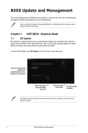
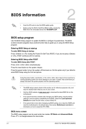
... motherboard's softwares, drivers and the BIOS version easily. With this utlity, you can use in the future. Chapter 1: UEFI BIOS - Graphics Mode 1.1 EZ Update EZ Update is a utility that you can also manually update the saved BIOS and select a boot logo when the system goes into POST. Save a copy of the original motherboard BIOS file to a USB flash disk in case you need to update the BIOS EZ Update requires an Internet connection either through a network or an ISP (Internet Service...
... motherboard's softwares, drivers and the BIOS version easily. With this utlity, you can use in the future. Chapter 1: UEFI BIOS - Graphics Mode 1.1 EZ Update EZ Update is a utility that you can also manually update the saved BIOS and select a boot logo when the system goes into POST. Save a copy of the original motherboard BIOS file to a USB flash disk in case you need to update the BIOS EZ Update requires an Internet connection either through a network or an ISP (Internet Service...
BIOSUpdateE-Manual English
Page 6
... system boot failure! 6 BIOS Update and Management Follow the steps below to update the BIOS via the Internet. e) Press the Up/Down arrow keys to find the USB flash disk that contains the latest BIOS, and then press . Enter the Advanced Mode of the BIOS setup program. Select the Load Optimized Defaults item under the Exit menu. Via the Internet a) Select by USB. DO NOT shut down or reset the...
... system boot failure! 6 BIOS Update and Management Follow the steps below to update the BIOS via the Internet. e) Press the Up/Down arrow keys to find the USB flash disk that contains the latest BIOS, and then press . Enter the Advanced Mode of the BIOS setup program. Select the Load Optimized Defaults item under the Exit menu. Via the Internet a) Select by USB. DO NOT shut down or reset the...

BIOSUpdateE-Manual English
Page 7
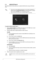
... removable device. • The BIOS file in the support DVD may not be the latest version. Recovering the BIOS To recover the BIOS: 1. When found, the utility reads the BIOS file and enters ASUS EZ Flash 3 utility automatically. 4. DO NOT shut down or reset the system while updating the BIOS! Turn on the system. 2. Doing so can restore a corrupted BIOS file using the motherboard support DVD or a USB flash drive that contains the BIOS file to load default BIOS values. You can cause system boot failure...
... removable device. • The BIOS file in the support DVD may not be the latest version. Recovering the BIOS To recover the BIOS: 1. When found, the utility reads the BIOS file and enters ASUS EZ Flash 3 utility automatically. 4. DO NOT shut down or reset the system while updating the BIOS! Turn on the system. 2. Doing so can restore a corrupted BIOS file using the motherboard support DVD or a USB flash drive that contains the BIOS file to load default BIOS values. You can cause system boot failure...
BIOSUpdateE-Manual English
Page 8
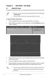
... Left/Right arrow keys to switch to select and update BIOS. 3. Text Mode 2.1 ASUS EZ Flash The ASUS EZ Flash feature allows you to find the BIOS file, and then press to the USB port. 2. Main Ai Tweaker Advanced Monitor Boot Tool Exit Start EzFlash Press ENTER to run the utility to the Folder Info field. 5. Reboot the system when the update process is done. • This function supports USB flash disks with FAT...
... Left/Right arrow keys to switch to select and update BIOS. 3. Text Mode 2.1 ASUS EZ Flash The ASUS EZ Flash feature allows you to find the BIOS file, and then press to the USB port. 2. Main Ai Tweaker Advanced Monitor Boot Tool Exit Start EzFlash Press ENTER to run the utility to the Folder Info field. 5. Reboot the system when the update process is done. • This function supports USB flash disks with FAT...
BIOSUpdateE-Manual English
Page 9
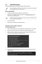
... same as the boot device. Before updating BIOS • Prepare the motherboard support DVD and a USB flash drive. • Download the latest BIOS file and BIOS Updater from the DVD/CD. When the booting message appears, press within 5 seconds, the system will boot next priority device automatically. Boot your USB flash drive. Please select boot device: and to move selection ENTER to select boot device ESC to boot using defaults P2: ST3808110AS (76319MB) aigo miniking (250MB) UEFI: (FAT) ASUS DRW-2014L1T...
... same as the boot device. Before updating BIOS • Prepare the motherboard support DVD and a USB flash drive. • Download the latest BIOS file and BIOS Updater from the DVD/CD. When the booting message appears, press within 5 seconds, the system will boot next priority device automatically. Boot your USB flash drive. Please select boot device: and to move selection ENTER to select boot device ESC to boot using defaults P2: ST3808110AS (76319MB) aigo miniking (250MB) UEFI: (FAT) ASUS DRW-2014L1T...
E11133MBPinDefinition English
Page 4
The onboard button cell battery powers the RAM data in CMOS. Keep the cap on CLRTC jumper default position. For system failure due to disable it . 1-4 E11133_MB_pin_definition_v2.indd 4 Motherboard Pin Definition 2015/12/28 17:21:47 Intel® ME jumper (3-pin DIS_ME) This jumper allows you to clear the CMOS RTC RAM data. Set this jumper to pins 1-2 to enable (default) the Intel® ME function and to pins 2-3 to overclocking, use the CPU Parameter Recall (C.P.R) feature...
The onboard button cell battery powers the RAM data in CMOS. Keep the cap on CLRTC jumper default position. For system failure due to disable it . 1-4 E11133_MB_pin_definition_v2.indd 4 Motherboard Pin Definition 2015/12/28 17:21:47 Intel® ME jumper (3-pin DIS_ME) This jumper allows you to clear the CMOS RTC RAM data. Set this jumper to pins 1-2 to enable (default) the Intel® ME function and to pins 2-3 to overclocking, use the CPU Parameter Recall (C.P.R) feature...

E11133MBPinDefinition English
Page 5
... CPU, DRAM in slow +5V +5VSB refresh, power supply in reduced power mode). (Default) • The USB device wake-up from S1 sleep mode (CPU stopped, DRAM refreshed, system running in sleep mode. 4. When you set this jumper to pins 2-3 (+5VSB), you to wake 12 23 up feature requires a power supply that can provide 500mA on the +5VSB lead, and a corresponding setting in the BIOS. 12 23 KB_USBPWB +5V +5VSB (Default) 5. This feature requires an ATX power supply...
... CPU, DRAM in slow +5V +5VSB refresh, power supply in reduced power mode). (Default) • The USB device wake-up from S1 sleep mode (CPU stopped, DRAM refreshed, system running in sleep mode. 4. When you set this jumper to pins 2-3 (+5VSB), you to wake 12 23 up feature requires a power supply that can provide 500mA on the +5VSB lead, and a corresponding setting in the BIOS. 12 23 KB_USBPWB +5V +5VSB (Default) 5. This feature requires an ATX power supply...

E11133MBPinDefinition English
Page 6
... the connector CHA_FAN CPU FAN PWM CPU FAN IN CPU FAN PWR GND +5V CHA FAN IN CHA FAN PWR GND Do not forget to connect the fan cables to connect a USB 3.0 module for USB-chargeable devices, optimized power efficiency, and PIN 1 backward compatibility with USB 2.0 specifications and supports up to 480Mbps connection speed. USB3 USB3+5V IntA_P2_SSRXIntA_P2_SSRX+ GND IntA_P2_SSTXIntA_P2_SSTX+ GND IntA_P2_DIntA_P2_D+ 4. USB 2.0 connector (10-1 pin) This connector is for USB 2.0 ports. Connect the serial port module cable to this connector, then install the module to a slot...
... the connector CHA_FAN CPU FAN PWM CPU FAN IN CPU FAN PWR GND +5V CHA FAN IN CHA FAN PWR GND Do not forget to connect the fan cables to connect a USB 3.0 module for USB-chargeable devices, optimized power efficiency, and PIN 1 backward compatibility with USB 2.0 specifications and supports up to 480Mbps connection speed. USB3 USB3+5V IntA_P2_SSRXIntA_P2_SSRX+ GND IntA_P2_SSTXIntA_P2_SSTX+ GND IntA_P2_DIntA_P2_D+ 4. USB 2.0 connector (10-1 pin) This connector is for USB 2.0 ports. Connect the serial port module cable to this connector, then install the module to a slot...

E11133MBPinDefinition English
Page 9
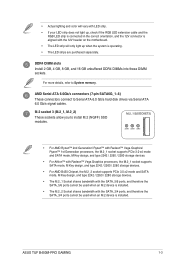
...install Windows® XP Service Pack 3 or later version before using Serial ATA hard disk drives. The SATAEXPRESS connector can create a RAID 0, 1, 5, and 10 configuration with the Intel® Rapid Storage Technology through the onboard Intel® chipset. Embedded DisplayPort (40- pin eDP) This connector is for an internal embedded DisplayPort connection. SATA 6.0Gb/s connectors (7-pin SATA6G) These connectors connect to SATA 6.0 Gb/s hard disk drives via SATA 6.0 Gb/s signal cables. If you installed SATA hard disk drives, you can support one SATA Express device or two SATA devices...
...install Windows® XP Service Pack 3 or later version before using Serial ATA hard disk drives. The SATAEXPRESS connector can create a RAID 0, 1, 5, and 10 configuration with the Intel® Rapid Storage Technology through the onboard Intel® chipset. Embedded DisplayPort (40- pin eDP) This connector is for an internal embedded DisplayPort connection. SATA 6.0Gb/s connectors (7-pin SATA6G) These connectors connect to SATA 6.0 Gb/s hard disk drives via SATA 6.0 Gb/s signal cables. If you installed SATA hard disk drives, you can support one SATA Express device or two SATA devices...

E11133MBPinDefinition English
Page 12
... system power LED lights up or flashes when data is for a chassis-mounted intrusion detection sensor or switch. Pressing the power button turns the system on or puts the system in sleep mode. • Hard disk drive activity LED (2-pin +HDD_LED-) +HDD_LED- Connect the chassis power LED cable to the HDD. • System warning speaker (4-pin SPEAKER) This 4-pin connector is for the chassis-mounted system warning speaker. RESET +PWR_LED- * Requires an ATX power supply This 2-pin connector is for the HDD Activity LED. The HDD LED lights up when PIN 1 CHASSIS...
... system power LED lights up or flashes when data is for a chassis-mounted intrusion detection sensor or switch. Pressing the power button turns the system on or puts the system in sleep mode. • Hard disk drive activity LED (2-pin +HDD_LED-) +HDD_LED- Connect the chassis power LED cable to the HDD. • System warning speaker (4-pin SPEAKER) This 4-pin connector is for the chassis-mounted system warning speaker. RESET +PWR_LED- * Requires an ATX power supply This 2-pin connector is for the HDD Activity LED. The HDD LED lights up when PIN 1 CHASSIS...

Users Manual English
Page 2
... COMPUTER INC. SPECIFICATIONS AND INFORMATION CONTAINED IN THIS MANUAL ARE FURNISHED FOR INFORMATIONAL USE ONLY, AND ARE SUBJECT TO CHANGE AT ANY TIME WITHOUT NOTICE, AND SHOULD NOT BE CONSTRUED AS A COMMITMENT BY ASUS. Offer to Provide Source Code of Certain Software This product contains copyrighted software that we would be extended if: (1) the product is repaired, modified or...
... COMPUTER INC. SPECIFICATIONS AND INFORMATION CONTAINED IN THIS MANUAL ARE FURNISHED FOR INFORMATIONAL USE ONLY, AND ARE SUBJECT TO CHANGE AT ANY TIME WITHOUT NOTICE, AND SHOULD NOT BE CONSTRUED AS A COMMITMENT BY ASUS. Offer to Provide Source Code of Certain Software This product contains copyrighted software that we would be extended if: (1) the product is repaired, modified or...
Users Manual English
Page 6
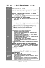
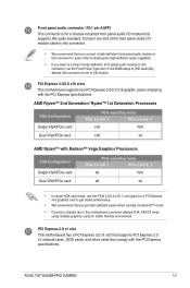
... output support: HDMI and DVI-D ports - Supports HDMI 2.0b with Radeon™ Vega Graphics/ Ryzen™ 1st Generation Processors - 4 x DIMMs, max. 64GB, DDR4 3533(O.C.)/ 3466(O.C.)/ 3200(O.C.)/ 3000(O.C)/ 2800(O.C.)/ 2666/ 2400/ 2133 MHz, un-buffered memory Dual-channel memory architecture * ECC memory (ECC mode) support varies by processor. ** Refer to www.asus.com for the latest Memory QVL (Qualified Vendors List). Package contents Check your motherboard package for the AMD CPU support list. TUF B450M-PRO GAMING specifications summary CPU Chipset Memory Expansion slots Graphics...
... output support: HDMI and DVI-D ports - Supports HDMI 2.0b with Radeon™ Vega Graphics/ Ryzen™ 1st Generation Processors - 4 x DIMMs, max. 64GB, DDR4 3533(O.C.)/ 3466(O.C.)/ 3200(O.C.)/ 3000(O.C)/ 2800(O.C.)/ 2666/ 2400/ 2133 MHz, un-buffered memory Dual-channel memory architecture * ECC memory (ECC mode) support varies by processor. ** Refer to www.asus.com for the latest Memory QVL (Qualified Vendors List). Package contents Check your motherboard package for the AMD CPU support list. TUF B450M-PRO GAMING specifications summary CPU Chipset Memory Expansion slots Graphics...
Users Manual English
Page 7
... immersive sound with the SATA_3/4 ports, and therefore the SATA_3/4 ports cannot be used when an M.2 device is installed. ASUS LANGuard - Protect your graphics card investment - TUF B450M-PRO GAMING specifications summary Multi-GPU support Storage LAN Audio USB ASUS unique features Supports AMD CrossFireX™ Technology AMD Ryzen™ 2nd Generation/ Ryzen™ with Radeon™ Vega Graphics/ Athlon™ with Radeon™ Vega Graphics/ Ryzen™ 1st Generation Processors - 2 x Serial ATA 6.0 Gb/s connectors with RAID 0, RAID 1 and RAID 10 support AMD Ryzen...
... immersive sound with the SATA_3/4 ports, and therefore the SATA_3/4 ports cannot be used when an M.2 device is installed. ASUS LANGuard - Protect your graphics card investment - TUF B450M-PRO GAMING specifications summary Multi-GPU support Storage LAN Audio USB ASUS unique features Supports AMD CrossFireX™ Technology AMD Ryzen™ 2nd Generation/ Ryzen™ with Radeon™ Vega Graphics/ Athlon™ with Radeon™ Vega Graphics/ Ryzen™ 1st Generation Processors - 2 x Serial ATA 6.0 Gb/s connectors with RAID 0, RAID 1 and RAID 10 support AMD Ryzen...
Users Manual English
Page 8
... 3.1 Gen 1 ports 2 x USB 2.0/1.1 connectors support additional 4 USB 2.0/1.1 ports 2 x M.2 socket 3 for M Key and type 2242/2260/2280 devices (both SATA mode & PCIe mode) 6 x SATA 6.0 Gb/s connectors 1 x COM connector 1 x CPU Fan connector 2 x Aura RGB Strip headers 2 x Chassis Fan connectors (Support DC & PWM mode) 1 x Front panel audio connector 1 x 24-pin EATX power connector 1 x 8-pin EATX 12V power connector 1 x 2-pin Clear CMOS header 1 x S/PDIF out connector 1 x Speaker connector 1 x System panel connector (continued on the next page) viii ASUS CrashFree BIOS 3 - TUF B450M-PRO GAMING...
... 3.1 Gen 1 ports 2 x USB 2.0/1.1 connectors support additional 4 USB 2.0/1.1 ports 2 x M.2 socket 3 for M Key and type 2242/2260/2280 devices (both SATA mode & PCIe mode) 6 x SATA 6.0 Gb/s connectors 1 x COM connector 1 x CPU Fan connector 2 x Aura RGB Strip headers 2 x Chassis Fan connectors (Support DC & PWM mode) 1 x Front panel audio connector 1 x 24-pin EATX power connector 1 x 8-pin EATX 12V power connector 1 x 2-pin Clear CMOS header 1 x S/PDIF out connector 1 x Speaker connector 1 x System panel connector (continued on the next page) viii ASUS CrashFree BIOS 3 - TUF B450M-PRO GAMING...
Users Manual English
Page 10
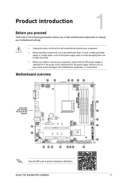
...) DDR4 DIMM_B2* (64bit, 288-pin module) 24.4cm(9.6in) SOCKET AM4 4 HDMI Place this U31G2_1 EATXPWR side towards the rear of the following precautions before you install motherboard components or change any motherboard settings. • Unplug the power cord from the power supply. ASUS TUF B450M-PRO GAMING 1-1 Product introduction 1 Before you proceed Take note of the U31G1_C5 1 chassis LAN_U31G1_34 BATTERY SATA6G_56 128Mb AUDIO BIOS Realtek® 6 8111H CHA_FAN2 M.2_1...
...) DDR4 DIMM_B2* (64bit, 288-pin module) 24.4cm(9.6in) SOCKET AM4 4 HDMI Place this U31G2_1 EATXPWR side towards the rear of the following precautions before you install motherboard components or change any motherboard settings. • Unplug the power cord from the power supply. ASUS TUF B450M-PRO GAMING 1-1 Product introduction 1 Before you proceed Take note of the U31G1_C5 1 chassis LAN_U31G1_34 BATTERY SATA6G_56 128Mb AUDIO BIOS Realtek® 6 8111H CHA_FAN2 M.2_1...
Users Manual English
Page 12
... SATA_3/4 ports cannot be used when an M.2 device is operating. • The LED strips are purchased separately. • Actual lighting and color will only light up when the system is installed. AMD Serial ATA 6.0Gb/s connectors (7-pin SATA6G_1~6) These connectors connect to install M.2 (NGFF) SSD modules. M.2 socket 3 (M.2_1, M.2_2) These sockets allow you to Serial ATA 6.0 Gb/s hard disk drives via Serial ATA 6.0 Gb/s signal cables. ASUS TUF B450M-PRO GAMING 1-3 For more details, refer to System memory.
... SATA_3/4 ports cannot be used when an M.2 device is operating. • The LED strips are purchased separately. • Actual lighting and color will only light up when the system is installed. AMD Serial ATA 6.0Gb/s connectors (7-pin SATA6G_1~6) These connectors connect to install M.2 (NGFF) SSD modules. M.2 socket 3 (M.2_1, M.2_2) These sockets allow you to Serial ATA 6.0 Gb/s hard disk drives via Serial ATA 6.0 Gb/s signal cables. ASUS TUF B450M-PRO GAMING 1-3 For more details, refer to System memory.
Users Manual English
Page 14
... use the PCIe 3.0/2.0 x16_1 slot (gray) for a PCI Express x16 graphics card to get better performance. • We recommend that comply with the PCI Express specifications. Front panel audio connector (10-1 pin AAFP) This connector is set the Front Panel Type item in the BIOS setup to [HD Audio].By default, this connector, set to [HD Audio]. PCI Express 2.0 x1 slot This motherboard has a PCI Express 2.0 x1 slot that supports PCI Express 2.0 x1 network cards, SCSI cards, and other cards that you provide sufficient power when running CrossFireX™ mode. • Connect a chassis fan...
... use the PCIe 3.0/2.0 x16_1 slot (gray) for a PCI Express x16 graphics card to get better performance. • We recommend that comply with the PCI Express specifications. Front panel audio connector (10-1 pin AAFP) This connector is set the Front Panel Type item in the BIOS setup to [HD Audio].By default, this connector, set to [HD Audio]. PCI Express 2.0 x1 slot This motherboard has a PCI Express 2.0 x1 slot that supports PCI Express 2.0 x1 network cards, SCSI cards, and other cards that you provide sufficient power when running CrossFireX™ mode. • Connect a chassis fan...
Users Manual English
Page 16
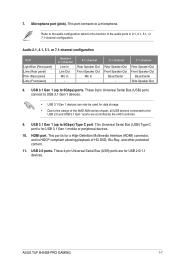
...) ports. ASUS TUF B450M-PRO GAMING 1-7 USB 3.1 Gen 1 (up to USB 3.1 Gen 1 devices. • USB 3.1 Gen 1 devices can only be used for USB 2.0/1.1 devices. These 9-pin Universal Serial Bus (USB) ports connect to 5Gbps) Type C port. Refer to the audio configuration table for the function of the AMD AM4 series chipset, all USB devices connected to the USB 2.0 and USB 3.1 Gen 1 ports are for data storage. • Due to a microphone. This port connects to the design of the audio ports in 2.1, 4.1, 5.1, or 7.1-channel configuration. These 4-pin Universal Serial Bus (USB...
...) ports. ASUS TUF B450M-PRO GAMING 1-7 USB 3.1 Gen 1 (up to USB 3.1 Gen 1 devices. • USB 3.1 Gen 1 devices can only be used for USB 2.0/1.1 devices. These 9-pin Universal Serial Bus (USB) ports connect to 5Gbps) Type C port. Refer to the audio configuration table for the function of the AMD AM4 series chipset, all USB devices connected to the USB 2.0 and USB 3.1 Gen 1 ports are for data storage. • Due to a microphone. This port connects to the design of the audio ports in 2.1, 4.1, 5.1, or 7.1-channel configuration. These 4-pin Universal Serial Bus (USB...
Users Manual English
Page 21
... modes. 2-1 ASUS TUF B450M-PRO GAMING See section Motherboard overview for this option only if you always shut down the system properly from a running operating system can be used under the Exit menu or press hotkey F5. • If the system fails to boot after POST: Press ++ simultaneously. Entering BIOS Setup at startup To enter BIOS Setup at www.asus.com to download the latest BIOS file for information on the system chassis. Entering BIOS Setup...
... modes. 2-1 ASUS TUF B450M-PRO GAMING See section Motherboard overview for this option only if you always shut down the system properly from a running operating system can be used under the Exit menu or press hotkey F5. • If the system fails to boot after POST: Press ++ simultaneously. Entering BIOS Setup at startup To enter BIOS Setup at www.asus.com to download the latest BIOS file for information on the system chassis. Entering BIOS Setup...


