User Guide
Page 16
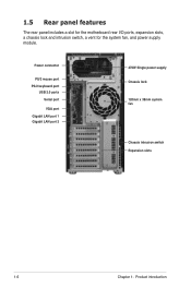
1.5 Rear panel features The rear panel includes a slot for the motherboard rear I/O ports, expansion slots, a chassis lock and intrusion switch, a vent for the system fan, and power supply module. Power connector PS/2 mouse port PS/2 keyboard port USB 2.0 ports Serial port VGA port Gigabit LAN port 1 Gigabit LAN port 2 470W Single power supply Chassis lock 120mm x 38mm system fan Chassis intrusion switch Expansion slots 1-6 Chapter 1: Product introduction
1.5 Rear panel features The rear panel includes a slot for the motherboard rear I/O ports, expansion slots, a chassis lock and intrusion switch, a vent for the system fan, and power supply module. Power connector PS/2 mouse port PS/2 keyboard port USB 2.0 ports Serial port VGA port Gigabit LAN port 1 Gigabit LAN port 2 470W Single power supply Chassis lock 120mm x 38mm system fan Chassis intrusion switch Expansion slots 1-6 Chapter 1: Product introduction
User Guide
Page 17
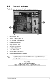
ASUS Z8NA-D6 Server Board 4. Optical drive (optional) 7. 2 x 5.25-inch drive bays 8. 4-bay HDD module 9. Expansion card locks 6. 1.6 Internal features The barebone server includes the basic components as shown. 1 6 7 2 9 8 3 4 10 5 1. Power supply unit: 2. 120mm x 38mm system fan 3. SATA/SAS backplane board 10. 80mm x 38mm system fan (hidden) Turn off the system power and detach the power supply before removing or replacing any system component. *WARNING HAZARDOUS MOVING PARTS KEEP FINGERS AND OTHER BODY PARTS AWAY ASUS TS500-E6/PS4 1-7 Chassis intrusion switch 5.
ASUS Z8NA-D6 Server Board 4. Optical drive (optional) 7. 2 x 5.25-inch drive bays 8. 4-bay HDD module 9. Expansion card locks 6. 1.6 Internal features The barebone server includes the basic components as shown. 1 6 7 2 9 8 3 4 10 5 1. Power supply unit: 2. 120mm x 38mm system fan 3. SATA/SAS backplane board 10. 80mm x 38mm system fan (hidden) Turn off the system power and detach the power supply before removing or replacing any system component. *WARNING HAZARDOUS MOVING PARTS KEEP FINGERS AND OTHER BODY PARTS AWAY ASUS TS500-E6/PS4 1-7 Chassis intrusion switch 5.
User Guide
Page 42
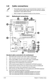
...8209;installed components to install additional devices. • Refer to SATA/SAS backplane J6 connector) 2-22 Chapter 2: Hardware setup Chassis Intrusion connector (from rear chassis intrusion switch to motherboard) 3. Motherboard connections 3 24 1 4 4 4 5 6 7 8 10 9 Standard cables connected to...system fan to motherboard) 4. SATA conectors (system default; System panel connector (from motherboard SGPIO3 to Chapter 4 for ASUS PIKE only; SAS connectors (for detailed information on the connectors. Serial General Purpose Input/Output connectors (SATA: from ...
...8209;installed components to install additional devices. • Refer to SATA/SAS backplane J6 connector) 2-22 Chapter 2: Hardware setup Chassis Intrusion connector (from rear chassis intrusion switch to motherboard) 3. Motherboard connections 3 24 1 4 4 4 5 6 7 8 10 9 Standard cables connected to...system fan to motherboard) 4. SATA conectors (system default; System panel connector (from motherboard SGPIO3 to Chapter 4 for ASUS PIKE only; SAS connectors (for detailed information on the connectors. Serial General Purpose Input/Output connectors (SATA: from ...

User Guide
Page 68
... panel features including front panel SMB, locator LED and switch, chassis intrusion, and LAN LEDs. 1. When you remove any chassis component, the sensor triggers and sends a high-level signal to record a chassis intrusion event. Auxiliary panel connector (20-pin AUX_PANEL1) This connector is for chassis with intrusion sensor or microswitch. This button queries the state of the...
... panel features including front panel SMB, locator LED and switch, chassis intrusion, and LAN LEDs. 1. When you remove any chassis component, the sensor triggers and sends a high-level signal to record a chassis intrusion event. Auxiliary panel connector (20-pin AUX_PANEL1) This connector is for chassis with intrusion sensor or microswitch. This button queries the state of the...
