User Guide
Page 11
ASUS TS500-E6/PS4 Product introduction Chapter 1 This chapter describes the general features of the server, including sections on front panel and rear panel specifications.
ASUS TS500-E6/PS4 Product introduction Chapter 1 This chapter describes the general features of the server, including sections on front panel and rear panel specifications.
User Guide
Page 12
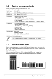
... Support team members can then offer a quicker and satisfying solution to your system package for the following items. Model Name TS500-E6/PS4 Chassis ASUS T50A Pedestal 5U Rackmount Chassis Motherboard ASUS Z8NA-D6 Server Board Component 1 x 470W Single Power Supply 4 x hot-swap HDD trays 1 x SAS/SATA2 Backplane with 4 x SATA Cables 1 x Front I/O Board 2 x System Fans...
... Support team members can then offer a quicker and satisfying solution to your system package for the following items. Model Name TS500-E6/PS4 Chassis ASUS T50A Pedestal 5U Rackmount Chassis Motherboard ASUS Z8NA-D6 Server Board Component 1 x 470W Single Power Supply 4 x hot-swap HDD trays 1 x SAS/SATA2 Backplane with 4 x SATA Cables 1 x Front I/O Board 2 x System Fans...
User Guide
Page 13
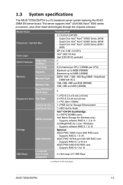
... 4.8 / 5.86 / 6.4 GT/s Intel® 5500 I/O Hub Intel ICH10R I = internal HDD Bays A or S = hot- 4 x Hot-swap 3.5" HDD Bays swappable (continued on the next page) ASUS TS500-E6/PS4 1-3 Supports RAID 0,1,5 & 10 I /O controller ASUS Features Smart Fan ASWM2.0 √ √ Total Slots 6 (3-channel per CPU, 3 DIMMs per CPU) Capacity Maximum up to 48GB (RDIMM) Maximum up to...
... 4.8 / 5.86 / 6.4 GT/s Intel® 5500 I/O Hub Intel ICH10R I = internal HDD Bays A or S = hot- 4 x Hot-swap 3.5" HDD Bays swappable (continued on the next page) ASUS TS500-E6/PS4 1-3 Supports RAID 0,1,5 & 10 I /O controller ASUS Features Smart Fan ASWM2.0 √ √ Total Slots 6 (3-channel per CPU, 3 DIMMs per CPU) Capacity Maximum up to 48GB (RDIMM) Maximum up to...
User Guide
Page 15
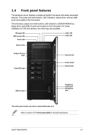
.... Refer to section 1.7.1 Front panel LEDs for the LED descriptions. The power and reset buttons, LED indicators, optical drive, and two USB ports are available. ASUS TS500-E6/PS4 1-5 Message LED HDD access LED Power LED LAN1 LED LAN2 LED Optical drive Empty 5.25-inch bays 4-bay HDD cage Security lock Power button Reset...
.... Refer to section 1.7.1 Front panel LEDs for the LED descriptions. The power and reset buttons, LED indicators, optical drive, and two USB ports are available. ASUS TS500-E6/PS4 1-5 Message LED HDD access LED Power LED LAN1 LED LAN2 LED Optical drive Empty 5.25-inch bays 4-bay HDD cage Security lock Power button Reset...
User Guide
Page 17
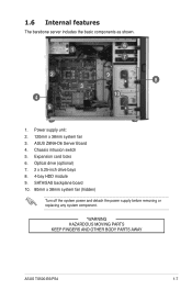
Optical drive (optional) 7. 2 x 5.25-inch drive bays 8. 4-bay HDD module 9. Expansion card locks 6. SATA/SAS backplane board 10. 80mm x 38mm system fan (hidden) Turn off the system power and detach the power supply before removing or replacing any system component. *WARNING HAZARDOUS MOVING PARTS KEEP FINGERS AND OTHER BODY PARTS AWAY ASUS TS500-E6/PS4 1-7 ASUS Z8NA-D6 Server Board 4. Power supply unit: 2. 120mm x 38mm system fan 3. Chassis intrusion switch 5. 1.6 Internal features The barebone server includes the basic components as shown. 1 6 7 2 9 8 3 4 10 5 1.
Optical drive (optional) 7. 2 x 5.25-inch drive bays 8. 4-bay HDD module 9. Expansion card locks 6. SATA/SAS backplane board 10. 80mm x 38mm system fan (hidden) Turn off the system power and detach the power supply before removing or replacing any system component. *WARNING HAZARDOUS MOVING PARTS KEEP FINGERS AND OTHER BODY PARTS AWAY ASUS TS500-E6/PS4 1-7 ASUS Z8NA-D6 Server Board 4. Power supply unit: 2. 120mm x 38mm system fan 3. Chassis intrusion switch 5. 1.6 Internal features The barebone server includes the basic components as shown. 1 6 7 2 9 8 3 4 10 5 1.
User Guide
Page 19
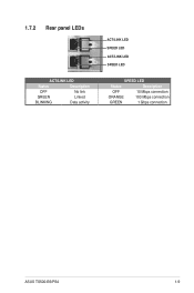
1.7.2 Rear panel LEDs ACT/LINK LED Status Description OFF No link GREEN Linked BLINKING Data activity ACT/LINK LED SPEED LED ACT/LINK LED SPEED LED SPEED LED Status Description OFF 10 Mbps connection ORANGE 100 Mbps connection GREEN 1 Gbps connection ASUS TS500-E6/PS4 1-9
1.7.2 Rear panel LEDs ACT/LINK LED Status Description OFF No link GREEN Linked BLINKING Data activity ACT/LINK LED SPEED LED ACT/LINK LED SPEED LED SPEED LED Status Description OFF 10 Mbps connection ORANGE 100 Mbps connection GREEN 1 Gbps connection ASUS TS500-E6/PS4 1-9
User Guide
Page 21
ASUS TS500-E6/PS4 Hardware setup Chapter 2 This chapter lists the hardware setup procedures that you have to perform when installing or removing system components.
ASUS TS500-E6/PS4 Hardware setup Chapter 2 This chapter lists the hardware setup procedures that you have to perform when installing or removing system components.
User Guide
Page 23
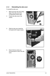
Drive in place. 1 3 4. 2.1.2 Reinstalling the side cover To reinstall the side cover: 1. Slide the side cover toward the front panel until it snaps in the two screws you removed earlier to the chassis. 3. Position the side cover to secure the side cover. 4 ASUS TS500-E6/PS4 4 2-3 Match and insert the lower sliding edge of the side cover to the corresponding chassis edge. 2.
Drive in place. 1 3 4. 2.1.2 Reinstalling the side cover To reinstall the side cover: 1. Slide the side cover toward the front panel until it snaps in the two screws you removed earlier to the chassis. 3. Position the side cover to secure the side cover. 4 ASUS TS500-E6/PS4 4 2-3 Match and insert the lower sliding edge of the side cover to the corresponding chassis edge. 2.
User Guide
Page 25
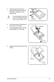
To prevent damage to a 135º angle. 4. Lift the load lever in the direction of the arrow to the socket pins, do not remove the PnP cap unless you are installing a CPU. Retention tab A B Load lever 3. Press the load lever with your thumb (A), then move it is released from the CPU socket. Lift the load plate with your thumb and forefinger to the left (B) until it to a 100º angle. 2. Load plate 4 3 5. Remove the PnP cap from the retention tab. PnP cap ASUS TS500-E6/PS4 2-5
To prevent damage to a 135º angle. 4. Lift the load lever in the direction of the arrow to the socket pins, do not remove the PnP cap unless you are installing a CPU. Retention tab A B Load lever 3. Press the load lever with your thumb (A), then move it is released from the CPU socket. Lift the load plate with your thumb and forefinger to the left (B) until it to a 100º angle. 2. Load plate 4 3 5. Remove the PnP cap from the retention tab. PnP cap ASUS TS500-E6/PS4 2-5
User Guide
Page 27
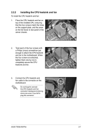
... to rear panel of the installed CPU, ensuring that the four screws match the holes on the support plate, and the arrow on the motherboard. ASUS TS500-E6/PS4 2-7
... to rear panel of the installed CPU, ensuring that the four screws match the holes on the support plate, and the arrow on the motherboard. ASUS TS500-E6/PS4 2-7
User Guide
Page 29
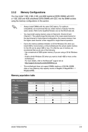
...You may install varying memory sizes in Channel A, Channel B and Channel C. The system maps the total size of 256 Mb (32MB) chips or less (Memory chip capacity counts in this section. • Always install DIMMs with the same .... Use a maximum of 3GB system memory if you are using the memory configurations in Megabit, 8 Megabit/Mb = 1 Megabyte/MB). For more on the ASUS web site. • You may install 1 GB, 2 GB, 4 GB, and 8GB registered DDR3 ... then mapped for the dual-channel or triple-channel configuration. ASUS TS500-E6/PS4 2-9 For effective use of the following: -
...You may install varying memory sizes in Channel A, Channel B and Channel C. The system maps the total size of 256 Mb (32MB) chips or less (Memory chip capacity counts in this section. • Always install DIMMs with the same .... Use a maximum of 3GB system memory if you are using the memory configurations in Megabit, 8 Megabit/Mb = 1 Megabyte/MB). For more on the ASUS web site. • You may install 1 GB, 2 GB, 4 GB, and 8GB registered DDR3 ... then mapped for the dual-channel or triple-channel configuration. ASUS TS500-E6/PS4 2-9 For effective use of the following: -
User Guide
Page 31
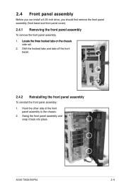
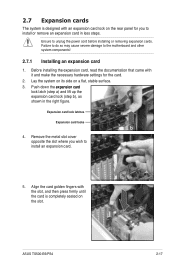
Hook the other side of the front panel assembly to the chassis. 2. ASUS TS500-E6/PS4 2-11 2.4 Front panel assembly Before you can install a 5.25-inch drive, you should first remove the front panel assembly (front bezel and front panel cover). 2.4.1 ...
Hook the other side of the front panel assembly to the chassis. 2. ASUS TS500-E6/PS4 2-11 2.4 Front panel assembly Before you can install a 5.25-inch drive, you should first remove the front panel assembly (front bezel and front panel cover). 2.4.1 ...
User Guide
Page 33
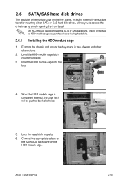
... purchase before buying hard disks. 2.6.1 Installing the HDD module cage 1. Connect the appropriate cables to access the drive trays by simply opening the front bezel. ASUS TS500-E6/PS4 5 2-13
... purchase before buying hard disks. 2.6.1 Installing the HDD module cage 1. Connect the appropriate cables to access the drive trays by simply opening the front bezel. ASUS TS500-E6/PS4 5 2-13
User Guide
Page 35
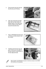
Carefully insert the drive tray and push it with four screws. 5. ASUS TS500-E6/PS4 2-15 Take note of the bay. 3. Firmly hold the tray lever and pull the drive tray out of the drive tray holes. Place a SATAII/SAS ...
Carefully insert the drive tray and push it with four screws. 5. ASUS TS500-E6/PS4 2-15 Take note of the bay. 3. Firmly hold the tray lever and pull the drive tray out of the drive tray holes. Place a SATAII/SAS ...
User Guide
Page 37
...;io�n��c�a��rd� lock latch (step a) and lift up the expansion card lock (step b), as a shown in less steps. ASUS TS500-E6/PS4 2-17
...;io�n��c�a��rd� lock latch (step a) and lift up the expansion card lock (step b), as a shown in less steps. ASUS TS500-E6/PS4 2-17
User Guide
Page 39
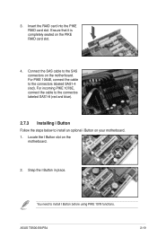
Locate the I Button in place. Snap the I Button slot on your motherboard. 1. ASUS TS500-E6/PS4 2-19 You need to the connectors labeled SAS1-4 (red). Insert the RAID card into the PIKE RAID card slot. For PIKE 1064E, connect the cable ...
Locate the I Button in place. Snap the I Button slot on your motherboard. 1. ASUS TS500-E6/PS4 2-19 You need to the connectors labeled SAS1-4 (red). Insert the RAID card into the PIKE RAID card slot. For PIKE 1064E, connect the cable ...
User Guide
Page 41
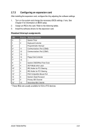
... and change the necessary BIOS settings, if any. Refer to the card. Install the software drivers for ISA or PCI devices. Turn on BIOS setup. 2. ASUS TS500-E6/PS4 2-21 Assign an IRQ to the following tables. 3. Programmable Interrupt 3* 11 Communications Port (COM2) 4* 12 Communications Port (COM1) 5* 13 -- 6 14 Floppy Disk Controller 7* 15 -- 8 3 System...
... and change the necessary BIOS settings, if any. Refer to the card. Install the software drivers for ISA or PCI devices. Turn on BIOS setup. 2. ASUS TS500-E6/PS4 2-21 Assign an IRQ to the following tables. 3. Programmable Interrupt 3* 11 Communications Port (COM2) 4* 12 Communications Port (COM1) 5* 13 -- 6 14 Floppy Disk Controller 7* 15 -- 8 3 System...
User Guide
Page 43
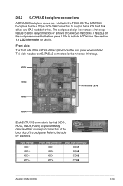
... drives. HDD Device HDD 1 HDD 2 HDD 3 HDD 4 Front side connector HDD1 HDD2 HDD3 HDD4 Back side connector CON�1 CON�2 CON�3 CON�4 ASUS TS500-E6/PS4 2-23 The SATA/SAS backplane has four 22-pin SATA/SAS connectors to indicate HDD status. Refer to allow easy connection or removal of the... can easily determine their counterpart connectors at the back side of the backplane. 2.8.2 SATA/SAS backplane connections A SATA/SAS backplane comes pre-installed in the TS500-E6.
... drives. HDD Device HDD 1 HDD 2 HDD 3 HDD 4 Front side connector HDD1 HDD2 HDD3 HDD4 Back side connector CON�1 CON�2 CON�3 CON�4 ASUS TS500-E6/PS4 2-23 The SATA/SAS backplane has four 22-pin SATA/SAS connectors to indicate HDD status. Refer to allow easy connection or removal of the... can easily determine their counterpart connectors at the back side of the backplane. 2.8.2 SATA/SAS backplane connections A SATA/SAS backplane comes pre-installed in the TS500-E6.
User Guide
Page 45
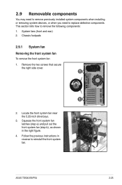
.... 3. Squeeze the front system fan latches (step a) and pull out the front system fan (step b), as shown in reverse to reinstall the front system fan. 1 a b a ASUS TS500-E6/PS4 2-25 System fans (front and rear) 2. Remove the two screws that secure the right side cover. 1 2. 2.9 Removable components You may need to remove previously installed...
.... 3. Squeeze the front system fan latches (step a) and pull out the front system fan (step b), as shown in reverse to reinstall the front system fan. 1 a b a ASUS TS500-E6/PS4 2-25 System fans (front and rear) 2. Remove the two screws that secure the right side cover. 1 2. 2.9 Removable components You may need to remove previously installed...
User Guide
Page 47
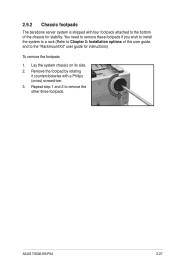
Repeat step 1 and 2 to the bottom of this user guide, and to the "Rackmount Kit" user guide for stability. Lay the system chassis on its side. 2. Remove the footpad by rotating it counterclockwise with four footpads attached to remove the other three footpads. ASUS TS500-E6/PS4 2-27 2.9.2 Chassis footpads The barebone server system is shipped with a Philips (cross) screwdriver. 3. You need to remove these footpads if you wish to install the system to a rack (Refer to Chapter 3: Installation options of the chassis for instructions) To remove the footpads 1.
Repeat step 1 and 2 to the bottom of this user guide, and to the "Rackmount Kit" user guide for stability. Lay the system chassis on its side. 2. Remove the footpad by rotating it counterclockwise with four footpads attached to remove the other three footpads. ASUS TS500-E6/PS4 2-27 2.9.2 Chassis footpads The barebone server system is shipped with a Philips (cross) screwdriver. 3. You need to remove these footpads if you wish to install the system to a rack (Refer to Chapter 3: Installation options of the chassis for instructions) To remove the footpads 1.