User Guide
Page 3
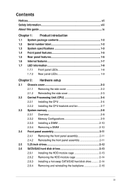
... 2.1 Chassis cover 2-2 2.1.1 Removing the side cover 2-2 2.1.2 Reinstalling the side cover 2-3 2.2 Central Processing Unit (CPU 2-4 2.2.1 Installing the CPU 2-4 2.2.2 Installing the CPU heatsink and fan 2-7 2.3 System memory 2-8 2.3.1 Overview 2-8 2.3.2 Memory Configurations 2-9 2.3.3 Installing a DIMM 2-10 2.3.4 Removing a DIMM 2-10 2.4 Front panel assembly 2-11 2.4.1 Removing the front panel assembly 2-11 2.4.2 Reinstalling the front panel assembly 2-11 2.5 5.25-inch...
... 2.1 Chassis cover 2-2 2.1.1 Removing the side cover 2-2 2.1.2 Reinstalling the side cover 2-3 2.2 Central Processing Unit (CPU 2-4 2.2.1 Installing the CPU 2-4 2.2.2 Installing the CPU heatsink and fan 2-7 2.3 System memory 2-8 2.3.1 Overview 2-8 2.3.2 Memory Configurations 2-9 2.3.3 Installing a DIMM 2-10 2.3.4 Removing a DIMM 2-10 2.4 Front panel assembly 2-11 2.4.1 Removing the front panel assembly 2-11 2.4.2 Reinstalling the front panel assembly 2-11 2.5 5.25-inch...
User Guide
Page 13
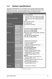
...TS500-E6/PS4 2 x Socket LGA1366 Processor / System Bus - Supports software RAID 0, 1 & 10 Storage Optional: ASUS PIKE 1064E 4-port SAS RAID card - Supports RAID 0,1,5 & 10 I /O controller ASUS Features Smart Fan ASWM2.0 √ √ Total Slots 6 (3-channel per CPU, 3 DIMMs per CPU) Capacity Maximum up to 48GB (RDIMM) Maximum up to 24GB (UDIMM) Memory Memory...4 x Hot-swap 3.5" HDD Bays swappable (continued on the next page) ASUS TS500-E6/PS4 1-3 The server supports Intel® LGA1366 Xeon® 5500 series processors, plus other latest technologies through the...
...TS500-E6/PS4 2 x Socket LGA1366 Processor / System Bus - Supports software RAID 0, 1 & 10 Storage Optional: ASUS PIKE 1064E 4-port SAS RAID card - Supports RAID 0,1,5 & 10 I /O controller ASUS Features Smart Fan ASWM2.0 √ √ Total Slots 6 (3-channel per CPU, 3 DIMMs per CPU) Capacity Maximum up to 48GB (RDIMM) Maximum up to 24GB (UDIMM) Memory Memory...4 x Hot-swap 3.5" HDD Bays swappable (continued on the next page) ASUS TS500-E6/PS4 1-3 The server supports Intel® LGA1366 Xeon® 5500 series processors, plus other latest technologies through the...
User Guide
Page 28
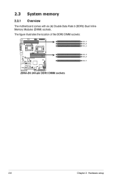
2.3 System memory 2.3.1 Overview The motherboard comes with six (6) Double Data Rate 3 (DDR3) Dual Inline Memory Modules (DIMM) sockets. The figure illustrates the location of the DDR3 DIMM sockets: 2-8 Chapter 2: Hardware setup
2.3 System memory 2.3.1 Overview The motherboard comes with six (6) Double Data Rate 3 (DDR3) Dual Inline Memory Modules (DIMM) sockets. The figure illustrates the location of the DDR3 DIMM sockets: 2-8 Chapter 2: Hardware setup
User Guide
Page 29
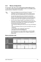
... 256 Mb (32MB) chips or less (Memory chip capacity counts in Channel A, Channel B and Channel C. Memory population table CPU 1 Configuration DIMM_A1 1 DIMMs 2 DIMMs 3 DIMMs CPU 2 Configuration DIMM_D1 1 DIMMs 2 DIMMs 3 DIMMs DIMM_B1 -- DIMM_C1 --- For effective use of the lower-sized channel for the OS can be about 3GB or less. DIMM_F1 --- ASUS TS500-E6/PS4 2-9 Any excess memory from...
... 256 Mb (32MB) chips or less (Memory chip capacity counts in Channel A, Channel B and Channel C. Memory population table CPU 1 Configuration DIMM_A1 1 DIMMs 2 DIMMs 3 DIMMs CPU 2 Configuration DIMM_D1 1 DIMMs 2 DIMMs 3 DIMMs DIMM_B1 -- DIMM_C1 --- For effective use of the lower-sized channel for the OS can be about 3GB or less. DIMM_F1 --- ASUS TS500-E6/PS4 2-9 Any excess memory from...
User Guide
Page 56
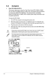
... in CMOS. Except when clearing the RTC RAM, never remove the cap on pins 2-3 for about 5-10 seconds, then move the jumper again to pins 2-3. Plug the power cord and turn ON the computer. 4. 4.2 Jumpers 1. You can clear the CMOS memory of date, time, and system setup parameters... by erasing the CMOS RTC RAM data. Keep the cap on CLRTC jumper default position. After the CMOS clearance, reinstall the battery. 4-4 Chapter 4: ...
... in CMOS. Except when clearing the RTC RAM, never remove the cap on pins 2-3 for about 5-10 seconds, then move the jumper again to pins 2-3. Plug the power cord and turn ON the computer. 4. 4.2 Jumpers 1. You can clear the CMOS memory of date, time, and system setup parameters... by erasing the CMOS RTC RAM data. Keep the cap on CLRTC jumper default position. After the CMOS clearance, reinstall the battery. 4-4 Chapter 4: ...
User Guide
Page 82
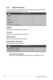
Processor Displays the auto-detected CPU specification. System Memory Displays the auto-detected system memory. System Memory Information Displays system memory information. The BIOS automatically detects the items in this menu. Main System Memory Information CPU1 Memory Configuration CPU2 Memory Configuration BIOS SETUP UTILITY CPU1/2 Memory Configuration Allows you an overview of installed memory (3 DIMMs per CPU). 5-12 Chapter 5: BIOS...
Processor Displays the auto-detected CPU specification. System Memory Displays the auto-detected system memory. System Memory Information Displays system memory information. The BIOS automatically detects the items in this menu. Main System Memory Information CPU1 Memory Configuration CPU2 Memory Configuration BIOS SETUP UTILITY CPU1/2 Memory Configuration Allows you an overview of installed memory (3 DIMMs per CPU). 5-12 Chapter 5: BIOS...
User Guide
Page 87
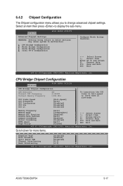
...Memory Frequency Memory Mode Memory ECC Function Double Rate Refresh Demand Scrubbing Patrol Scrubbing NUMA Aware Page Policy [Auto] [Independent] [Enabled] [Auto] [Enabled] [Disabled] [Auto] [Closed] +F1 F10 ESC Select Screen Select Item Change Option General Help Save and Exit Exit v02.61 (C)Copyright 1985-2009, American Megatrends, Inc. ASUS TS500-E6/PS4... SETUP UTILITY CPU Bridge Chipset Configuration CPU Revision :B0 Current CSI Frequency :4.800GT Current Memory Frequency :1066 Mhz CSI Links Speed CSI Frequency CSI Isochronous CSI L0s CSI L1 [...
...Memory Frequency Memory Mode Memory ECC Function Double Rate Refresh Demand Scrubbing Patrol Scrubbing NUMA Aware Page Policy [Auto] [Independent] [Enabled] [Auto] [Enabled] [Disabled] [Auto] [Closed] +F1 F10 ESC Select Screen Select Item Change Option General Help Save and Exit Exit v02.61 (C)Copyright 1985-2009, American Megatrends, Inc. ASUS TS500-E6/PS4... SETUP UTILITY CPU Bridge Chipset Configuration CPU Revision :B0 Current CSI Frequency :4.800GT Current Memory Frequency :1066 Mhz CSI Links Speed CSI Frequency CSI Isochronous CSI L0s CSI L1 [...
User Guide
Page 88
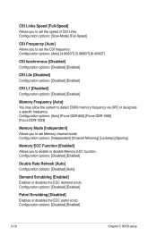
...L0s [Disabled] Configuration options: [Disabled] [Enabled] CSI L1 [Disabled] Configuration options: [Disabled] [Enabled] Memory Frequency [Auto] You may allow the system to detect DDR3 memory frequency via SPD or designate a specific frequency. Configuration options: [Disabled] [Enabled] 5-18 Chapter 5: BIOS setup... Demand Scrubbing [Enabled] Enables or disables the ECC demand scrub. Configuration options: [Independent] [Channel Mirroring] [Lockstep] [Sparing] Memory ECC Function [Enabled] Allows you to set the speed of CSI Links. Configuration options: [Slow-Mode] [Full-Speed] CSI ...
...L0s [Disabled] Configuration options: [Disabled] [Enabled] CSI L1 [Disabled] Configuration options: [Disabled] [Enabled] Memory Frequency [Auto] You may allow the system to detect DDR3 memory frequency via SPD or designate a specific frequency. Configuration options: [Disabled] [Enabled] 5-18 Chapter 5: BIOS setup... Demand Scrubbing [Enabled] Enables or disables the ECC demand scrub. Configuration options: [Independent] [Channel Mirroring] [Lockstep] [Sparing] Memory ECC Function [Enabled] Allows you to set the speed of CSI Links. Configuration options: [Slow-Mode] [Full-Speed] CSI ...
User Guide
Page 99
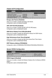
Configuration options: [Disabled] [Enabled] HPET Memory Address [FED00000h] Configuration options: [FED00000h] [FED01000h] [FED02000h] [FED03000h] General WHEA Configuration Advanced BIOS... Bridge ACPI Configuration Energy Lake Feature APIC ACPI SCI IRQ USB Device Wakeup From S3/S4 High Performance Event Timer HPET Memory Address [Disabled] [Disabled] [Disabled] [Enabled] [FED00000h] Options Enabled Disabled Energy Lake Feature [Disabled] Allows you ...enable or disable the USB device wakeup from S3/S4 feature. Configuration options: [Disabled] [Enabled] ASUS TS500-E6/PS4 5-29
Configuration options: [Disabled] [Enabled] HPET Memory Address [FED00000h] Configuration options: [FED00000h] [FED01000h] [FED02000h] [FED03000h] General WHEA Configuration Advanced BIOS... Bridge ACPI Configuration Energy Lake Feature APIC ACPI SCI IRQ USB Device Wakeup From S3/S4 High Performance Event Timer HPET Memory Address [Disabled] [Disabled] [Disabled] [Enabled] [FED00000h] Options Enabled Disabled Energy Lake Feature [Disabled] Allows you ...enable or disable the USB device wakeup from S3/S4 feature. Configuration options: [Disabled] [Enabled] ASUS TS500-E6/PS4 5-29
User Guide
Page 151
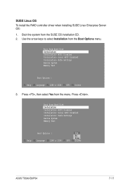
... Yes from Hard Disk Installation Installation--ACPI Disabled Installation--Local APIC Disabled Installation--Safe Settings Rescue System Memory Test Boot Options | Yes No File F1 Help F2 Language F3 1280 x 1024 F4 DVD F5 Driver ASUS TS500-E6/PS4 7-11 Press . Boot from the Boot Options menu. Use the arrow keys to select Installation from...
... Yes from Hard Disk Installation Installation--ACPI Disabled Installation--Local APIC Disabled Installation--Safe Settings Rescue System Memory Test Boot Options | Yes No File F1 Help F2 Language F3 1280 x 1024 F4 DVD F5 Driver ASUS TS500-E6/PS4 7-11 Press . Boot from the Boot Options menu. Use the arrow keys to select Installation from...
User Guide
Page 152
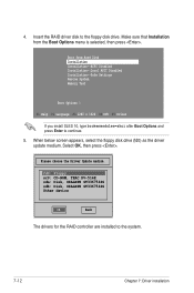
... drive. Select OK, then press . Make sure that Installation from Hard Disk Installation Installation--ACPI Disabled Installation--Local APIC Disabled Installation--Safe Settings Rescue System Memory Test Boot Options | F1 Help F2 Language F3 1280 x 1024 F4 DVD F5 Driver If you install SLES 10, type brokenmodules=ahci after Boot Options...
... drive. Select OK, then press . Make sure that Installation from Hard Disk Installation Installation--ACPI Disabled Installation--Local APIC Disabled Installation--Safe Settings Rescue System Memory Test Boot Options | F1 Help F2 Language F3 1280 x 1024 F4 DVD F5 Driver If you install SLES 10, type brokenmodules=ahci after Boot Options...

