User Guide
Page 4
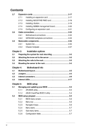
... options 3.1 Preparing the system for rack mounting 3-2 3.2 Attaching the inner rail to the server 3-2 3.3 Attaching the rails to the rack 3-3 3.4 Mounting the server to the rack 3-4 Chapter 4: Motherboard Info 4.1 Motherboard layout 4-2 4.2 Jumpers 4-4 4.3 ...Internal connectors 4-9 4.4 Internal LEDs 4-17 Chapter 5: BIOS setup 5.1 Managing and updating your BIOS 5-2 5.1.1 AFUDOS utility 5-2 5.1.2 ASUS CrashFree BIOS 3 utility 5-4 5.2 BIOS setup...
... options 3.1 Preparing the system for rack mounting 3-2 3.2 Attaching the inner rail to the server 3-2 3.3 Attaching the rails to the rack 3-3 3.4 Mounting the server to the rack 3-4 Chapter 4: Motherboard Info 4.1 Motherboard layout 4-2 4.2 Jumpers 4-4 4.3 ...Internal connectors 4-9 4.4 Internal LEDs 4-17 Chapter 5: BIOS setup 5.1 Managing and updating your BIOS 5-2 5.1.1 AFUDOS utility 5-2 5.1.2 ASUS CrashFree BIOS 3 utility 5-4 5.2 BIOS setup...
User Guide
Page 5
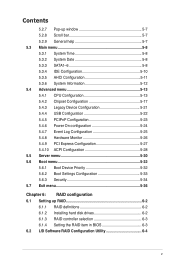
... 5.4.4 USB Configuration 5-22 5.4.5 PCIPnP Configuration 5-23 5.4.6 Power On configuration 5-24 5.4.7 Event Log Configuration 5-25 5.4.8 Hardware Monitor 5-26 5.4.9 PCI Express Configuration 5-27 5.4.10 ACPI Configuration 5-28 5.5 Server menu 5-30 5.6 Boot menu 5-32 5.6.1 Boot Device Priority 5-32 5.6.2 Boot Settings Configuration 5-33 5.6.3 Security 5-34 5.7 Exit menu 5-36 Chapter 6: RAID configuration 6.1 Setting up RAID 6-2 6.1.1 RAID...
... 5.4.4 USB Configuration 5-22 5.4.5 PCIPnP Configuration 5-23 5.4.6 Power On configuration 5-24 5.4.7 Event Log Configuration 5-25 5.4.8 Hardware Monitor 5-26 5.4.9 PCI Express Configuration 5-27 5.4.10 ACPI Configuration 5-28 5.5 Server menu 5-30 5.6 Boot menu 5-32 5.6.1 Boot Device Priority 5-32 5.6.2 Boot Settings Configuration 5-33 5.6.3 Security 5-34 5.7 Exit menu 5-36 Chapter 6: RAID configuration 6.1 Setting up RAID 6-2 6.1.1 RAID...
User Guide
Page 8
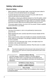
... viii Operation Safety • Servicing of used batteries according to fix it by trained service personnel only. • Before operating the server, carefully read all attached devices are unplugged. • To prevent electrical shock hazard, disconnect the power cable from the existing system ..., disconnect all cables are correctly connected and the power cables are not damaged. This product is equipped with the server package. • Before using the server, make sure all power cables from the electrical outlet before relocating the system. • When adding or removing...
... viii Operation Safety • Servicing of used batteries according to fix it by trained service personnel only. • Before operating the server, carefully read all attached devices are unplugged. • To prevent electrical shock hazard, disconnect the power cable from the existing system ..., disconnect all cables are correctly connected and the power cables are not damaged. This product is equipped with the server package. • Before using the server, make sure all power cables from the electrical outlet before relocating the system. • When adding or removing...
User Guide
Page 9
...system settings through the BIOS Setup menus and describes the BIOS parameters. 6. This symbol of electronic products. This symbol of the server, including sections on front panel and rear panel specifications. 2. Contents This guide contains the following parts: 1. Chapter 5: BIOS... information This chapter tells how to install the optional components and devices into the barebone server. 4. DO NOT throw the mercury-containing button cell battery in municipal waste. Chapter 4: Motherboard information This chapter includes the motherboard...
...system settings through the BIOS Setup menus and describes the BIOS parameters. 6. This symbol of electronic products. This symbol of the server, including sections on front panel and rear panel specifications. 2. Contents This guide contains the following parts: 1. Chapter 5: BIOS... information This chapter tells how to install the optional components and devices into the barebone server. 4. DO NOT throw the mercury-containing button cell battery in municipal waste. Chapter 4: Motherboard information This chapter includes the motherboard...
User Guide
Page 10
... how to complete a task. DANGER/WARNING: Information to prevent injury to yourself when trying to set up and use the proprietary ASUS server management utility. 2. Keys enclosed in brackets. References Example: At the DOS prompt, type the command line: format A:/S Refer to... the following symbols used throughout this manual. ASUS websites The ASUS websites worldwide provide updated information for product and software updates. 1. CAUTION: Information to prevent damage to the components when trying to...
... how to complete a task. DANGER/WARNING: Information to prevent injury to yourself when trying to set up and use the proprietary ASUS server management utility. 2. Keys enclosed in brackets. References Example: At the DOS prompt, type the command line: format A:/S Refer to... the following symbols used throughout this manual. ASUS websites The ASUS websites worldwide provide updated information for product and software updates. 1. CAUTION: Information to prevent damage to the components when trying to...
User Guide
Page 11
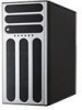
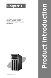
ASUS TS500-E6/PS4 Product introduction Chapter 1 This chapter describes the general features of the server, including sections on front panel and rear panel specifications.
ASUS TS500-E6/PS4 Product introduction Chapter 1 This chapter describes the general features of the server, including sections on front panel and rear panel specifications.
User Guide
Page 12
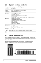
... Support team members can then offer a quicker and satisfying solution to your system package for the following items. Model Name TS500-E6/PS4 Chassis ASUS T50A Pedestal 5U Rackmount Chassis Motherboard ASUS Z8NA-D6 Server Board Component 1 x 470W Single Power Supply 4 x hot-swap HDD trays 1 x SAS/SATA2 Backplane with 4 x SATA Cables 1 x Front I/O Board 2 x System Fans (Front...
... Support team members can then offer a quicker and satisfying solution to your system package for the following items. Model Name TS500-E6/PS4 Chassis ASUS T50A Pedestal 5U Rackmount Chassis Motherboard ASUS Z8NA-D6 Server Board Component 1 x 470W Single Power Supply 4 x hot-swap HDD trays 1 x SAS/SATA2 Backplane with 4 x SATA Cables 1 x Front I/O Board 2 x System Fans (Front...
User Guide
Page 13
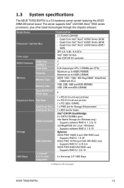
... 3.5" HDD Bays swappable (continued on the next page) ASUS TS500-E6/PS4 1-3 Quad-Core Intel® Xeon® E5500 Series (80W) - Supports software RAID 0, 1 & 10 Storage Optional: ASUS PIKE 1064E 4-port SAS RAID card - 1.3 System specifications The ASUS TS500-E6/PS4 is a 5U barebone server system featuring the ASUS Z8NA-D6 server board. The server supports Intel® LGA1366 Xeon® 5500 series...
... 3.5" HDD Bays swappable (continued on the next page) ASUS TS500-E6/PS4 1-3 Quad-Core Intel® Xeon® E5500 Series (80W) - Supports software RAID 0, 1 & 10 Storage Optional: ASUS PIKE 1064E 4-port SAS RAID card - 1.3 System specifications The ASUS TS500-E6/PS4 is a 5U barebone server system featuring the ASUS Z8NA-D6 server board. The server supports Intel® LGA1366 Xeon® 5500 series...
User Guide
Page 14
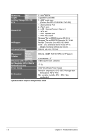
... Serial Port 2 x RJ-45 ports 4 x USB 2.0 ports (Front x 2, Rear x 2) 1 x VGA port 1 x PS/2 keyboard port 1 x PS/2 mouse port Windows® Server 2008 Enterprise 32 / 64-bit Windows® Server 2003 R2 Enterprise 32 / 64-bit RedHat® Enterprise Linux AS5.0 32 / 64-bit SuSE® Linux Enterprise...Product introduction condensing) *Specifications are subject to change without any notice) Optional anti-virus CD Pack Optional ASMB4-iKVM for KVM-over-IP support ASUS ASWM 2.0® 445mm x 217.5mm x 545mm 17 Kg 470W (80+) Single Power Supply Operation temperature: 10°C-35°C / Non...
... Serial Port 2 x RJ-45 ports 4 x USB 2.0 ports (Front x 2, Rear x 2) 1 x VGA port 1 x PS/2 keyboard port 1 x PS/2 mouse port Windows® Server 2008 Enterprise 32 / 64-bit Windows® Server 2003 R2 Enterprise 32 / 64-bit RedHat® Enterprise Linux AS5.0 32 / 64-bit SuSE® Linux Enterprise...Product introduction condensing) *Specifications are subject to change without any notice) Optional anti-virus CD Pack Optional ASMB4-iKVM for KVM-over-IP support ASUS ASWM 2.0® 445mm x 217.5mm x 545mm 17 Kg 470W (80+) Single Power Supply Operation temperature: 10°C-35°C / Non...
User Guide
Page 15
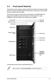
..., floppy drive, and USB 2.0 ports are located on the front panel. ASUS TS500-E6/PS4 1-5 Refer to section 1.7.1 Front panel LEDs for the LED descriptions. For future installation of 5.25-inch devices, two drive bays are available. 1.4 Front panel features The barebone server displays a simple yet stylish front panel with an optional MIO audio card.
..., floppy drive, and USB 2.0 ports are located on the front panel. ASUS TS500-E6/PS4 1-5 Refer to section 1.7.1 Front panel LEDs for the LED descriptions. For future installation of 5.25-inch devices, two drive bays are available. 1.4 Front panel features The barebone server displays a simple yet stylish front panel with an optional MIO audio card.
User Guide
Page 17
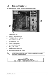
Power supply unit: 2. 120mm x 38mm system fan 3. SATA/SAS backplane board 10. 80mm x 38mm system fan (hidden) Turn off the system power and detach the power supply before removing or replacing any system component. *WARNING HAZARDOUS MOVING PARTS KEEP FINGERS AND OTHER BODY PARTS AWAY ASUS TS500-E6/PS4 1-7 1.6 Internal features The barebone server includes the basic components as shown. 1 6 7 2 9 8 3 4 10 5 1. Chassis intrusion switch 5. ASUS Z8NA-D6 Server Board 4. Optical drive (optional) 7. 2 x 5.25-inch drive bays 8. 4-bay HDD module 9. Expansion card locks 6.
Power supply unit: 2. 120mm x 38mm system fan 3. SATA/SAS backplane board 10. 80mm x 38mm system fan (hidden) Turn off the system power and detach the power supply before removing or replacing any system component. *WARNING HAZARDOUS MOVING PARTS KEEP FINGERS AND OTHER BODY PARTS AWAY ASUS TS500-E6/PS4 1-7 1.6 Internal features The barebone server includes the basic components as shown. 1 6 7 2 9 8 3 4 10 5 1. Chassis intrusion switch 5. ASUS Z8NA-D6 Server Board 4. Optical drive (optional) 7. 2 x 5.25-inch drive bays 8. 4-bay HDD module 9. Expansion card locks 6.
User Guide
Page 27
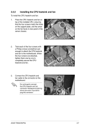
... to connect the CPU heatsink and fan connector! ASUS TS500-E6/PS4 2-7 Place the CPU heatsink and fan on top of the installed CPU, ensuring that the four screws match the holes on the support plate, and the arrow on the motherboard. Twist each of the server chassis. 2. Do not forget to plug this connector...
... to connect the CPU heatsink and fan connector! ASUS TS500-E6/PS4 2-7 Place the CPU heatsink and fan on top of the installed CPU, ensuring that the four screws match the holes on the support plate, and the arrow on the motherboard. Twist each of the server chassis. 2. Do not forget to plug this connector...
User Guide
Page 47
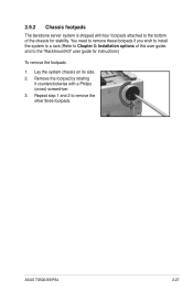
You need to remove these footpads if you wish to install the system to a rack (Refer to Chapter 3: Installation options of the chassis for instructions) To remove the footpads 1. Remove the footpad by rotating it counterclockwise with four footpads attached to remove the other three footpads. Repeat step 1 and 2 to the bottom of this user guide, and to the "Rackmount Kit" user guide for stability. Lay the system chassis on its side. 2. 2.9.2 Chassis footpads The barebone server system is shipped with a Philips (cross) screwdriver. 3. ASUS TS500-E6/PS4 2-27
You need to remove these footpads if you wish to install the system to a rack (Refer to Chapter 3: Installation options of the chassis for instructions) To remove the footpads 1. Remove the footpad by rotating it counterclockwise with four footpads attached to remove the other three footpads. Repeat step 1 and 2 to the bottom of this user guide, and to the "Rackmount Kit" user guide for stability. Lay the system chassis on its side. 2. 2.9.2 Chassis footpads The barebone server system is shipped with a Philips (cross) screwdriver. 3. ASUS TS500-E6/PS4 2-27
User Guide
Page 49
Installation options Chapter 3 This chapter describes how to install the optional components and devices into the barebone server. ASUS TS500-E6/PS4
Installation options Chapter 3 This chapter describes how to install the optional components and devices into the barebone server. ASUS TS500-E6/PS4
User Guide
Page 50
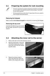
... footpads for the optional configurations described in the standard barebone system package. Repeat the previous steps to secure the other inner rail to the server 1. Removing the top cover Unscrew and slide the top cover toward the rear panel, and then lift it up from the rackmount rail kit...2. These items are not included in this chapter are purchased separately. • We recommend that you allot at least 1U space above the server system to ensure optimal thermal performance. Slide out the inner rail from the chassis. 3.2 Attaching the inner rail to the bottom of the ...
... footpads for the optional configurations described in the standard barebone system package. Repeat the previous steps to secure the other inner rail to the server 1. Removing the top cover Unscrew and slide the top cover toward the rear panel, and then lift it up from the rackmount rail kit...2. These items are not included in this chapter are purchased separately. • We recommend that you allot at least 1U space above the server system to ensure optimal thermal performance. Slide out the inner rail from the chassis. 3.2 Attaching the inner rail to the bottom of the ...

User Guide
Page 51
... pair. Align the front end holes of space (1U) on the rack rails. 3. ASUS TS500-E6/PS4 3-3 Select one unit of a rack rail pair to secure the rear end. 7. Drive in two screws on the outer holes to install the server. 2. From the rack front, find the corresponding 1U space for the second rail pair...
... pair. Align the front end holes of space (1U) on the rack rails. 3. ASUS TS500-E6/PS4 3-3 Select one unit of a rack rail pair to secure the rear end. 7. Drive in two screws on the outer holes to install the server. 2. From the rack front, find the corresponding 1U space for the second rail pair...

User Guide
Page 52
3.4 Mounting the server to the rack To mount the server to the rack: 1. Align the server rails with the rack rails. 2. Push the server all the way into the rack. 3-4 Chapter 3: Installation options
3.4 Mounting the server to the rack To mount the server to the rack: 1. Align the server rails with the rack rails. 2. Push the server all the way into the rack. 3-4 Chapter 3: Installation options
User Guide
Page 65
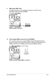
BMC header (BMC_FW1) The BMC connector on the motherboard supports an ASUS® Server Management Board 4 Series (ASMB4). 10. ASUS TS500-E6/PS4 4-13 9. Power Supply SMBus connector (5-pin PSUSMB1) This connector allows you to connect SMBus (System Management Bus) to the power supply unit to read PSU information. Devices communicate with an SMBus host and/or other SMBus devices using the SMBus interface.
BMC header (BMC_FW1) The BMC connector on the motherboard supports an ASUS® Server Management Board 4 Series (ASMB4). 10. ASUS TS500-E6/PS4 4-13 9. Power Supply SMBus connector (5-pin PSUSMB1) This connector allows you to connect SMBus (System Management Bus) to the power supply unit to read PSU information. Devices communicate with an SMBus host and/or other SMBus devices using the SMBus interface.
User Guide
Page 76
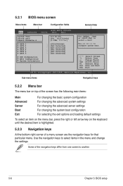
...on top of the screen has the following main items: Main Advanced Server Boot Exit For changing the basic system configuration For changing the advanced system settings For changing the advanced server settings For changing the system boot configuration For selecting the exit options ... screen to another. 5-6 Chapter 5: BIOS setup 5.2.1 BIOS menu screen Menu items Menu bar Configuration fields General help Main Advanced BIOS SETUP UTILITY Server Boot Exit System Time [13:44:30] System Date [Fri, 02/27/2009] Legacy Diskette A [1.44M, 3.5 in the menu and change...
...on top of the screen has the following main items: Main Advanced Server Boot Exit For changing the basic system configuration For changing the advanced system settings For changing the advanced server settings For changing the system boot configuration For selecting the exit options ... screen to another. 5-6 Chapter 5: BIOS setup 5.2.1 BIOS menu screen Menu items Menu bar Configuration fields General help Main Advanced BIOS SETUP UTILITY Server Boot Exit System Time [13:44:30] System Date [Fri, 02/27/2009] Legacy Diskette A [1.44M, 3.5 in the menu and change...
User Guide
Page 78
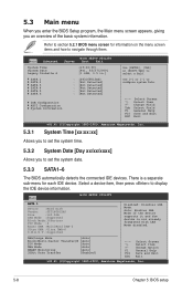
... Mode :4 Async DMA :MultiWord DMA-2 Ultra DMA :Ultra DMA-6 S.M.A.R.T.:Supported Disabled: Disables LBA Mode. Use [+] or [-] to navigate through them. Main Advanced BIOS SETUP UTILITY Server Boot Exit System Time [13:44:30] System Date [Fri, 02/27/2009] Legacy Diskette A [1.44M, 3.5 in.] SATA 1 SATA 2 SATA 3 SATA 4 SATA 5 SATA 6 : [ST3160812AS] : [Not...
... Mode :4 Async DMA :MultiWord DMA-2 Ultra DMA :Ultra DMA-6 S.M.A.R.T.:Supported Disabled: Disables LBA Mode. Use [+] or [-] to navigate through them. Main Advanced BIOS SETUP UTILITY Server Boot Exit System Time [13:44:30] System Date [Fri, 02/27/2009] Legacy Diskette A [1.44M, 3.5 in.] SATA 1 SATA 2 SATA 3 SATA 4 SATA 5 SATA 6 : [ST3160812AS] : [Not...