
User Guide
Page 1
Motherboard SABERTOOTH Z170 MARK 1
Motherboard SABERTOOTH Z170 MARK 1
User Guide
Page 3
... power connection 2-8 2.1.6 SATA device connection 2-9 2.1.7 Front I/O Connector 2-10 2.1.8 Expansion Card installation 2-11 2.2 BIOS update utility 2-12 2.3 Motherboard rear and audio connections 2-13 2.3.1 Rear I/O connection 2-13 iii Contents Safety information...vi About this guide...vii SABERTOOTH Z170 MARK 1 specifications summary ix Package contents...xiv Installation tools and components xv Chapter 1: Product Introduction 1.1 Special features 1-1 1.1.1 Product...
... power connection 2-8 2.1.6 SATA device connection 2-9 2.1.7 Front I/O Connector 2-10 2.1.8 Expansion Card installation 2-11 2.2 BIOS update utility 2-12 2.3 Motherboard rear and audio connections 2-13 2.3.1 Rear I/O connection 2-13 iii Contents Safety information...vi About this guide...vii SABERTOOTH Z170 MARK 1 specifications summary ix Package contents...xiv Installation tools and components xv Chapter 1: Product Introduction 1.1 Special features 1-1 1.1.1 Product...
User Guide
Page 6
... the product in your dealer immediately. • To avoid short circuits, keep paper clips, screws, and staples away from the motherboard, ensure that the power cables for the devices are unplugged before you encounter technical problems with the package. • Before using... circuit. • Ensure that came with the product, contact a qualified service technician or your retailer. Operation safety • Before installing the motherboard and adding devices on a stable surface. • If you add a device. • Before connecting or removing signal cables from connectors, ...
... the product in your dealer immediately. • To avoid short circuits, keep paper clips, screws, and staples away from the motherboard, ensure that the power cables for the devices are unplugged before you encounter technical problems with the package. • Before using... circuit. • Ensure that came with the product, contact a qualified service technician or your retailer. Operation safety • Before installing the motherboard and adding devices on a stable surface. • If you add a device. • Before connecting or removing signal cables from connectors, ...
User Guide
Page 7
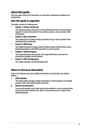
How this guide This user guide contains the information you have been added by your dealer. ASUS websites The ASUS website provides updated information on the motherboard. • Chapter 2: Basic Installation This chapter lists the hardware setup procedures that may include optional documentation, such as warranty flyers, that you need when installing ...
How this guide This user guide contains the information you have been added by your dealer. ASUS websites The ASUS website provides updated information on the motherboard. • Chapter 2: Basic Installation This chapter lists the hardware setup procedures that may include optional documentation, such as warranty flyers, that you need when installing ...

User Guide
Page 14
... for the following items: User Manual ASUS SABERTOOTH Z170 MARK 1 motherboard Technical documentations, certification and warranty card Support DVD 4 x Serial ATA 6.0 Gb/s cables 1 x ASUS SLI™ bridge connector (7 cm) 1 x ASUS Q-Shield 1 x ASUS Q-Connector kit 2 x Assistant fans (40 mm & 35 mm) 2 x DRAM slot covers TUF ... caps 2 x Short fan screws 4 x Long fan screws 2 x M.2 screws package 1 x back I/O dust frame 1 x back I/O dust grid ASUS HYPER M.2 X4 MINI quick start guide 1 x Hyper M.2 X4 Mini Card 1 x Low-profile bracket • If any of the above items is damaged...
... for the following items: User Manual ASUS SABERTOOTH Z170 MARK 1 motherboard Technical documentations, certification and warranty card Support DVD 4 x Serial ATA 6.0 Gb/s cables 1 x ASUS SLI™ bridge connector (7 cm) 1 x ASUS Q-Shield 1 x ASUS Q-Connector kit 2 x Assistant fans (40 mm & 35 mm) 2 x DRAM slot covers TUF ... caps 2 x Short fan screws 4 x Long fan screws 2 x M.2 screws package 1 x back I/O dust frame 1 x back I/O dust grid ASUS HYPER M.2 X4 MINI quick start guide 1 x Hyper M.2 X4 Mini Card 1 x Low-profile bracket • If any of the above items is damaged...

User Guide
Page 15
Installation tools and components Graphics card (optional) Phillips (cross) screwdriver PC chassis Power supply unit Intel® LGA1151 CPU Intel® LGA1151 compatible CPU Fan DIMM SATA hard disk drive SATA optical disc drive (optional) The tools and components in the table above are not included in the motherboard package. xv
Installation tools and components Graphics card (optional) Phillips (cross) screwdriver PC chassis Power supply unit Intel® LGA1151 CPU Intel® LGA1151 compatible CPU Fan DIMM SATA hard disk drive SATA optical disc drive (optional) The tools and components in the table above are not included in the motherboard package. xv

User Guide
Page 17
... natively supports up to PCIe 1.0/2.0 devices. QUAD-GPU SLI and 3-WAY CrossFireX™ Support The motherboard features Quad-GPU SLI and 3-Way AMD CrossfireX support that provides twice the performance and speed of the same speed. SABERTOOTH Z170 MARK 1 1-1 It provides great graphics and system performance with its GPU, dual-channel DDR4 memory slots...
... natively supports up to PCIe 1.0/2.0 devices. QUAD-GPU SLI and 3-WAY CrossFireX™ Support The motherboard features Quad-GPU SLI and 3-Way AMD CrossfireX support that provides twice the performance and speed of the same speed. SABERTOOTH Z170 MARK 1 1-1 It provides great graphics and system performance with its GPU, dual-channel DDR4 memory slots...
User Guide
Page 18
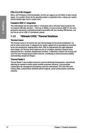
...Armor is completely backward-compatible with dual Type-A ports for better system stability and power efficiency. Complete USB 3.1 integration This motherboard has the latest USB 3.1 connectivity built in a faster pace. It safeguards the system against hot air generated by connected... power saving solution, and noise reduction. 1-2 Chapter 1: Product Introduction Thermal Radar 2 Thermal Radar 2 uses multiple sensors to control motherboard temperatures, automatically adjusting fan speeds for the very fastest USB data transfers - The nextgeneration standard is the world's first ever thermal...
...Armor is completely backward-compatible with dual Type-A ports for better system stability and power efficiency. Complete USB 3.1 integration This motherboard has the latest USB 3.1 connectivity built in a faster pace. It safeguards the system against hot air generated by connected... power saving solution, and noise reduction. 1-2 Chapter 1: Product Introduction Thermal Radar 2 Thermal Radar 2 uses multiple sensors to control motherboard temperatures, automatically adjusting fan speeds for the very fastest USB data transfers - The nextgeneration standard is the world's first ever thermal...

User Guide
Page 19
... Engine" Power Design Digital Power Control ASUS DIGI+ Power Control features the revolutionary and innovative digital VRM, DRAM, and CPU Voltage controllers. It also makes the motherboard easier to support the Thermal Armor, CPU, VGA card, additional expansion cards, and other peripherals. SABERTOOTH Z170 MARK 1 1-3 It reinforces the motherboard's PCB to handle and helps protect your...
... Engine" Power Design Digital Power Control ASUS DIGI+ Power Control features the revolutionary and innovative digital VRM, DRAM, and CPU Voltage controllers. It also makes the motherboard easier to support the Thermal Armor, CPU, VGA card, additional expansion cards, and other peripherals. SABERTOOTH Z170 MARK 1 1-3 It reinforces the motherboard's PCB to handle and helps protect your...
User Guide
Page 20
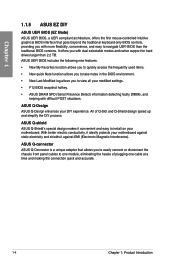
...New quick Note function allows you to take notes in the BIOS environment. • New Last Modified log allows you to view all your motherboard. ASUS Q-shield ASUS Q-Shield's special design makes it against static electricity and shields it convenient and easy to install on your modified settings. • F12 BIOS...front panel cables to one module, eliminating the hassle of Q-Slot and Q-Shield design speed up and simplify the DIY process. ASUS Q-Design ASUS Q-Design enhances your motherboard against EMI (Electronic Magnetic Interference). It offers you with difficult POST situations.
...New quick Note function allows you to take notes in the BIOS environment. • New Last Modified log allows you to view all your motherboard. ASUS Q-shield ASUS Q-Shield's special design makes it against static electricity and shields it convenient and easy to install on your modified settings. • F12 BIOS...front panel cables to one module, eliminating the hassle of Q-Slot and Q-Shield design speed up and simplify the DIY process. ASUS Q-Design ASUS Q-Design enhances your motherboard against EMI (Electronic Magnetic Interference). It offers you with difficult POST situations.
User Guide
Page 21
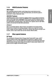
...ASUS Exclusive Features USB Charger+ With a dedicated onboard controller, quick-charge all your ultimate convenience. It allows you to regularly check for about three seconds, and the UEFI BIOS is in line with no need to switch back and forth between different utilities. 1.1.7 Other special features ErP Ready The motherboard... -use functions, with ASUS vision of creating environment-friendly and energyefficient products through product design and innovation to energy consumptions. SABERTOOTH Z170 MARK 1 1-5 AI Suite 3 With its user-friendly interface, ASUS AI Suite 3 consolidates all...
...ASUS Exclusive Features USB Charger+ With a dedicated onboard controller, quick-charge all your ultimate convenience. It allows you to regularly check for about three seconds, and the UEFI BIOS is in line with no need to switch back and forth between different utilities. 1.1.7 Other special features ErP Ready The motherboard... -use functions, with ASUS vision of creating environment-friendly and energyefficient products through product design and innovation to energy consumptions. SABERTOOTH Z170 MARK 1 1-5 AI Suite 3 With its user-friendly interface, ASUS AI Suite 3 consolidates all...
User Guide
Page 22
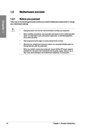
..., to avoid damaging them due to static electricity. • Hold components by the edges to the motherboard, peripherals, or components. 1-6 Chapter 1: Product Introduction Chapter 1 1.2 Motherboard overview 1.2.1 Before you proceed Take note of the following precautions before you install motherboard components or change any motherboard settings. • Unplug the power cord from the power supply.
..., to avoid damaging them due to static electricity. • Hold components by the edges to the motherboard, peripherals, or components. 1-6 Chapter 1: Product Introduction Chapter 1 1.2 Motherboard overview 1.2.1 Before you proceed Take note of the following precautions before you install motherboard components or change any motherboard settings. • Unplug the power cord from the power supply.

User Guide
Page 23
SABERTOOTH Z170 MARK 1 1-7 1.2.2 Motherboard layout Chapter 1 Refer to 1.2.9 Internal connectors and 2.3.1 Rear I/O connection for more information about rear panel connectors and internal connectors.
SABERTOOTH Z170 MARK 1 1-7 1.2.2 Motherboard layout Chapter 1 Refer to 1.2.9 Internal connectors and 2.3.1 Rear I/O connection for more information about rear panel connectors and internal connectors.
User Guide
Page 25
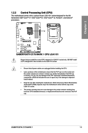
ASUS will shoulder the cost of the PnP cap. SABERTOOTH Z170 MARK 1 1-9 DO NOT install a CPU designed for other sockets on the socket and the socket contacts are unplugged before installing the CPU. • Upon purchase of the motherboard, ensure that you see any damage to the socket contacts...the damage is on the LGA1151 socket. • Ensure that all power cables are not bent. ASUS will process Return Merchandise Authorization (RMA) requests only if the motherboard comes with a surface mount LGA1151 socket designed for LGA1151 socket only. Contact your retailer immediately if ...
ASUS will shoulder the cost of the PnP cap. SABERTOOTH Z170 MARK 1 1-9 DO NOT install a CPU designed for other sockets on the socket and the socket contacts are unplugged before installing the CPU. • Upon purchase of the motherboard, ensure that you see any damage to the socket contacts...the damage is on the LGA1151 socket. • Ensure that all power cables are not bent. ASUS will process Return Merchandise Authorization (RMA) requests only if the motherboard comes with a surface mount LGA1151 socket designed for LGA1151 socket only. Contact your retailer immediately if ...

User Guide
Page 26
Recommended memory configurations 1-10 Chapter 1: Product Introduction DO NOT install a DDR, DDR2, or DDR3 memory module to the DDR4 slot. Chapter 1 1.2.4 System memory The motherboard comes with four Double Data Rate 4 (DDR4) Dual Inline Memory Modules (DIMM) slots. A DDR4 module is notched differently from a DDR, DDR2, or DDR3 module.
Recommended memory configurations 1-10 Chapter 1: Product Introduction DO NOT install a DDR, DDR2, or DDR3 memory module to the DDR4 slot. Chapter 1 1.2.4 System memory The motherboard comes with four Double Data Rate 4 (DDR4) Dual Inline Memory Modules (DIMM) slots. A DDR4 module is notched differently from a DDR, DDR2, or DDR3 module.

User Guide
Page 27
...® support site at http://support.microsoft. c) For more on the CPU's capabilities and other installed devices. SABERTOOTH Z170 MARK 1 1-11 com/kb/929605/en-us. • This motherboard does not support DIMMs made up of individual CPUs or Memory. • Memory module with memory frequency higher than... install 2 GB, 4 GB, 8 GB, and 16 GB unbuffered and non‑ECC DDR4 DIMMs into the DIMM sockets. Visit the ASUS website at www.asus.com for overclocking may operate at a lower frequency than 2133 MHz and its Serial Presence Detect (SPD), which is not the JEDEC memory ...
...® support site at http://support.microsoft. c) For more on the CPU's capabilities and other installed devices. SABERTOOTH Z170 MARK 1 1-11 com/kb/929605/en-us. • This motherboard does not support DIMMs made up of individual CPUs or Memory. • Memory module with memory frequency higher than... install 2 GB, 4 GB, 8 GB, and 16 GB unbuffered and non‑ECC DDR4 DIMMs into the DIMM sockets. Visit the ASUS website at www.asus.com for overclocking may operate at a lower frequency than 2133 MHz and its Serial Presence Detect (SPD), which is not the JEDEC memory ...

User Guide
Page 28
Chapter 1 Slot No. 1 2 3 4 5 6 Slot Description PCIE 2.0 x1_1 slot PCIE 3.0/2.0 x16_1 slot PCIE 2.0 x1_2 slot PCIE 3.0/2.0 x16_2 slot PCIE 2.0 x1_4 slot PCIE 3.0/2.0 x16_3 slot 1-12 Chapter 1: Product Introduction 1.2.5 Expansion slots Unplug the power cord before adding or removing expansion cards. Failure to do so may cause you physical injury and damage motherboard components.
Chapter 1 Slot No. 1 2 3 4 5 6 Slot Description PCIE 2.0 x1_1 slot PCIE 3.0/2.0 x16_1 slot PCIE 2.0 x1_2 slot PCIE 3.0/2.0 x16_2 slot PCIE 2.0 x1_4 slot PCIE 3.0/2.0 x16_3 slot 1-12 Chapter 1: Product Introduction 1.2.5 Expansion slots Unplug the power cord before adding or removing expansion cards. Failure to do so may cause you physical injury and damage motherboard components.

User Guide
Page 29
... xHCI shared - - - - - - - PCIe x1_3 - - - shared - - - - ASMedia SATA Controller1 (1061) - SABERTOOTH Z170 MARK 1 1-13 PCIe x1_1 - - - PCIe x1_2 - - HD Audio shared - - - - - - - PCIe x16_2 - PCIe... recommend that you provide sufficient power when running CrossFireX™ or SLI™ mode. • Connect a chassis fan to the motherboard connector labeled CHA_FAN1-4 when using multiple graphics cards for this motherboard A B C D E F G H PCIe x16_1 shared - - - - - - - IRQ assignments for better thermal environment...
... xHCI shared - - - - - - - PCIe x1_3 - - - shared - - - - ASMedia SATA Controller1 (1061) - SABERTOOTH Z170 MARK 1 1-13 PCIe x1_1 - - - PCIe x1_2 - - HD Audio shared - - - - - - - PCIe x16_2 - PCIe... recommend that you provide sufficient power when running CrossFireX™ or SLI™ mode. • Connect a chassis fan to the motherboard connector labeled CHA_FAN1-4 when using multiple graphics cards for this motherboard A B C D E F G H PCIe x16_1 shared - - - - - - - IRQ assignments for better thermal environment...
User Guide
Page 30
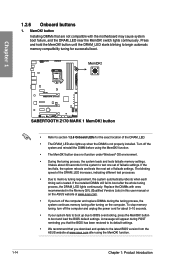
... Product Introduction If the test fails, the system reboots and tests the next set is not properly installed. Replace the DIMMs with the motherboard may cause system boot failure, and the DRAM_LED near the MemOK! switch lights continuously. The blinking speed of the DRAM_LED. •... the exact location of the DRAM_LED increases, indicating different test processes. • Due to the latest BIOS version from the ASUS website at www.asus.com. • If you download and update to memory tuning requirement, the system automatically reboots when each timing set of failsafe...
... Product Introduction If the test fails, the system reboots and tests the next set is not properly installed. Replace the DIMMs with the motherboard may cause system boot failure, and the DRAM_LED near the MemOK! switch lights continuously. The blinking speed of the DRAM_LED. •... the exact location of the DRAM_LED increases, indicating different test processes. • Due to the latest BIOS version from the ASUS website at www.asus.com. • If you download and update to memory tuning requirement, the system automatically reboots when each timing set of failsafe...

User Guide
Page 33
Standby Power LED (SBPWR) The motherboard comes with a standby power LED. The illustration below shows the location of these key components during POST (Power-On-Self Test): CPU, memory modules, VGA card, and hard disk drives. SABERTOOTH Z170 MARK 1 1-17 If an error is found, the critical component's LED stays lit up to indicate that...
Standby Power LED (SBPWR) The motherboard comes with a standby power LED. The illustration below shows the location of these key components during POST (Power-On-Self Test): CPU, memory modules, VGA card, and hard disk drives. SABERTOOTH Z170 MARK 1 1-17 If an error is found, the critical component's LED stays lit up to indicate that...


